Texmate, Inc. Tel. (760) 598-9899 • www.texmate.comBL-40-TC _ BL-40-RTD manual (d0044) Page 1
• Thermocouple(J,K,RandTtypes)orRTD(Pt-100.385and
392curves.3wire/4wire).DigitallyLinearized.
• Optionalisolated16bitanalogoutput.Userorfactoryscalable
to4to20mA,0to20mAor0to10Vacrossanydesired
digitalspanfrom±onecounttothefullscalerangeof–1999
to9999(12000counts).
•
Auto-sensingAC/DCpowersupply.Forvoltagesbetween
85-265 V AC / 95-300 V DC (PS1)or15-48VAC/10-72VDC(PS2).
• Standardredoroptionalgreenorsuperbrightred4-digitLED
• ThreeannunciatorLEDsprovidefrontpanelalarmstatus
indicationforuptothreesetpoints.
• One9AmpFormCandone4AmpFormArelay,orupto
three4AmpFormArelaysareavailable.
• Whenanalogoutputisinstalled,one9AmpFormCortwo
4AmpFormArelayscanbesupported.
General Features
Specifications
Software Features
Index
Input Specs:..............Dependsoninputsignalconditioner
A/D Converter:..........14bitsingleslope
Accuracy:..................±(0.05%ofreading+2counts)
Temp. Coeff.:.............100ppm/°C(Typical)
Warm up time:...........2minutes
Conversion Rate:......5conversionspersecond(Typical)
Display:......................4 digit 0.56" Red LED display (std),
0.56”GreenorSuperBrightRed(optn).
Range
–1999to9999counts.
Polarity:.....................Assumedpositive.Displays–negative
Decimal Selection:....AutomaticbyresolutionselectXXX•X
Positive Overrange:. . Topsegmentsofdigitaldisplayflash
Negative Overrange: Bottomsegmentsofdigitaldisplayflash
Relay Output:............
Three4AmpFormArelaysorone9Amp
FormC,andone4AmpFormArelay.
Analog Output:.........Isolated16bituserscalablemAorV
OIC(mAout)...........
4-20mA@0to500Ωmaxloopresistance
OIV(voltsout).......... 0-10VDC@500Ωorhigherresistance
Power Supply:...........AC/DCAutosensingwiderangesupply
PS1 (std)................
85-265 VAC / 95-300 VDC @ 2.5W max 3.2W
PS2.........................
15-48VAC/10-72VDC@2.5Wmax3.2W
Operating Temp.:......0to50°C
Storage Temp:...........–20°Cto70°C.
Relative Humidity:....95%(noncondensing)
Case Dimensions:....1/16DIN,Bezel:96x24mm(3.78”x0.95”)
Depthbehindbezel122.2mm(4.83")
Plus12.7mm(0.5”)forRight-angled
connector.
Weight:.......................7oz.,9ozwhenpacked
BrightnessSelection..............5
CalibrationProcedure.............4
CaseDimensions ................8
ComponentLayout ...............8
ConnectorPinouts...............7
Connectors .....................7
ControlsandIndicators...........2
DigitalSpanSelectionforAnalogRange
Output.........................5
GeneralFeatures ................1
GlossaryofProgrammingSymbols. . 2
InputModuleCompatibility.........1
OrderingInformation.............9
PinDescriptions .................7
SetpointSetting&RelayConfiguration
Mode..........................6
SoftwareFeatures...............1
SoftwareLogicTree ..............3
Specifications ...................1
ThermocoupleorRTDSensorType
Selection.......................4
TwoPointAnalogOutputRangeSetting
andCalibration ..................5
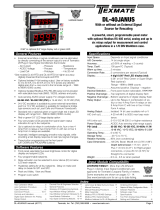
A smart Temperature Controller/Transmitter
for J, K, R, and T type Thermocouple
and RTD inputs.
Selectrable from F to C and 1˚ to 0.1˚ res.
Input Module Compatibility
Thereare2differentPlug-inModularInputSignalConditioners
forthisspecializedtemperatureonlymemberoftheLeopard
Family.IT10isforJ,K,TandRthermocouples.IT11isfor3
wire/4wirePt-100RTDinputs.
• Three-buttonprogrammingfromthefrontpanel
(UP,DOWNandPROGRAMbuttons).
• Threefrontpanelselectableranges.
• Frontpanelselectable
four-levelbrightnesscontrolofdigitaldis-
play
.
•
Threeprogrammablesetpoints.
• Relayactivationcanbeselectedtooccurabove(HI)orbelow
(LO)eachsetpoint.
• Hysteresissettingforallthreesetpoints.Delayonmakeand
delayonbreakforSP1andSP2.
LEOPARD FAMILY
BL-40-TC
BL-40-RTD
4 Digit 0.56" LEDs in a 1/16 DIN Case

Texmate, Inc. Tel. (760) 598-9899 • www.texmate.comPage2 BL-40-TC _ BL-40-RTD manual (d0044)
Glossary of Programming Symbols
Symbol Explanation
Controls and Indicators
Whentwodisplaysareshowntogetherwith
bursts, this indicates that the display is
toggling(flashing)betweenthenameofthe
functionandthevalue.
Text or numbers shown between square
brackets in a procedure indicate the pro-
grammingcodenameofthefunctionorthe
valuedisplayedonthemeterdisplay.
When the
and
buttons are shown
together,thedisplayvaluecanbeincreased
by pressing and releasing the
button
ordecreasedbypressingandreleasingthe
button.
When the
and
buttons are shown
with two displays, either display can be
selectedbypressingandreleasingthe
or
buttons.
Whentherearemorethantwodisplayselec-
tions they are shown in brackets below the
firstdisplayandarealsoselectablebypress-
ingandreleasingthe
or
buttons.
A dotted box indicates these functions are
omittedorbypassedwhentherelatedhard-
wareisnotpresent
Toexplainsoftwareprogrammingprocedures,logicdiagramsare
usedtovisuallyassistinfollowingtheprogrammingsteps.The
fol-lowingsymbolsareusedthroughoutthelogicdiagramstorep-
resentthebuttonsandindicatorsonthemeter:
[Span]
[10000]
[LhL-]
[hLh-]
[LLL-]
Front Panel Buttons
Program Button
The
P
buttonisusedtomovefromoneprogramsteptothenext.
When pressed at the same time as the button, it initiates the
calibration mode.Whenpressedatthesametimeasthe but-
ton,itinitiatesthesetpoint setting mode.
Up Button
When in the operational display, pressing the button alone
allowsyoutoview,butnotchange,thesettingofsetpoint 1.
Wheninthecalibration modeorthesetpoint setting modethe
buttonisusedtoincreasethevalueofthedisplayedparameter.
Down Button
When in the operational display, pressing the button alone
allowsyoutoview,butnotchange,thesettingofsetpoint 2.
Wheninthecalibration modeorthesetpoint setting modethe
buttonisusedtodecreasethevalueofthedisplayedparameter.
This symbol represents the
OPERATIONALDISPLAY.
ThisisthePROGRAMbutton.
ThisistheUPbutton.
ThisistheDOWNbutton.
When a button is shown, press and
release it to go onto the next step in the
directionindicatedbythearrow.Whentwo
ormorebuttonsareshown,eachwithan
arrow,thisindicatesthatthereisanumber
ofprogrammingchoices.
Whentwobuttonsareshownsidebyside
andenclosed by a dotted line, they must
bepressedatthesametimethen
released
togoontothenextprogrammingstep.
Ifthe displayis shownwith XXXXit means
thevaluedisplayedwillbethepreviouslyset
value.Whenanumberisshownitindicates
theinitialfactorydefaultsettingoraspecific
“examplenumber”.
P
UPARROW
BUTTON
DOWNARROW
BUTTON
Setpoint
AnnunciatorLEDs
SP3
SP2
SP1
PROGRAM
BUTTON P
Programlockoutheader
behindfaceplate.

Texmate, Inc. Tel. (760) 598-9899 • www.texmate.comBL-40-TC _ BL-40-RTD manual (d0044) Page3
SETPOINT SETTING AND
RELAY CONFIGURATION MODE
See Page 6
Set Setpoint 1
(SP1)
Setpoint 2
(SP2)
Hysteresis
(HYST)
Hysteresis
(HYST)
Hysteresis
(HYST)
Setpoint 3
(SP3)
If set point 3 and 4 are installed
Relays Activation [rLYS]
(H) High the relay energizes
when the setpoint is exceeded.
(L) Low the relay energizes below
the setpoint. Setpoint are indicated
from left to right SP1, SP2, SP3, SP4
[LhL-]
[hLh-]
[hhh-]
MAIN MENU
Operational Display
Sub-menu
MODE
Calibration
Mode
BRIGHTNESS SELECTION
See Page 5
Calibrate
Analog
Output
Lo
° C
° F
Calibrate
Analog
Output
Hi
[2]
[3]
[4]
Display
Brightness (br)
TWO POINT ANALOG OUTPUT
RANGE SETTING AND
CALIBRATION
See Page 5
DIGITAL SPAN
SELECTION FOR ANALOG
RANGE OUTPUT
See Page 5
SETPOINT
VIEW ONLY MODE
SETPOINT
VIEW ONLY MODE
Set points can not be changed
in the SETPOINT VIEW ONLY MODE.
Example
[K]
[r]
[t]
If RTD module is installed
3 or 4 wire
RTD input
selection
RTD select type
P385 or P392
If analog O/P
is present
If analog O/P is present
Displays °C or °F
whichever is the
opposite of the
selected
operational
display
If Thermocouple module is installed
Program lock
is engaged
Program lock
is engaged
Resolution select
Thermocouple select
Select J, K, R or T
1°
0.1°
Degree select
°C
°F
THERMOCOUPLE OR RTD TYPE,
RESOLUTION AND DEGREE
C OR °F SELECT
See Page 4
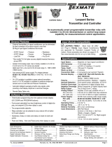
Software Logic Tree
The BL-40-TC and BL-40-RTD are an intelligent meter
withahierarchicalsoftwarestructuredesignedforeasy
programmingandoperation,asshownbelowinthesoft-
warelogictree.
Afterthemeterhasbeenpoweredup,thefourdigits
light up for three seconds and then settle to the
operationaldisplayindicatingtheinputsignal.
15 Second Program Timeout
Themeterhasa15secondprogramtimeout.If
nobuttonsarepressedfor15seconds,atany
stageoftheprogrammingsequencethemeter
will exit the programming mode and return to
the operational display.Any program changes
thatweremadepriortopressingthe
P
button
intheprecedingstepwillnotbesaved.
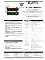
Input Sensor
Reso-
lution °
C Range °F Range
J T/C
K T/C
R T/C
T T/C
100Ω RTD
(385 curve)
100Ω RTD
(392 curve)
-120 to 760°C
-120 to 530°C
-120 to 1370°C
-120 to 530°C
0 to 1760°C
0 to 530°C
-120 to 400°C
-120 to 400°C
-200 to 800°C
-199.9 to 530°C
-200 to 800°C
-199.9 to 530°C
-200 to 1400°F
-199.9 to 999.9°F
-200 to 2500°F
-199.9 to 999.9°F
32 to 3210°F
32 to 999.9°F
-200 to 750°F
-199.9 to 750.0°F
-200 to 1470°F
-199.9 to 999.9°F
-200 to 1470°F
-199.9 to 999.9°F
Sensor Range Table
1°
0.1°
1°
0.1°
1°
0.1°
1°
0.1°
1°
0.1°
1°
0.1°

Texmate, Inc. Tel. (760) 598-9899 • www.texmate.comPage4 BL-40-TC _ BL-40-RTD manual (d0044)
IT10 Thermocouple Input Signal Conditioner installed.
1. Unplugtheconnectorplugsfromthemeter.Removethe
casebackpanelandslidethePCBoutofthecase.
2. Selecttheappropriateheaderjumperpositiondepending
onwhichthermocoupleistobeused.Thermocouple
typesJ,K,RandTaresupported.Thissetsupthecor-
rectcoldjunctioncompensation.
3. InsertthePCBbackintothecase.Snapthebackpanel
backintothecase.Applypowertothemeter.
4. Entertheprogrammodeandselectthetypeofthermo-
couple(J,K,R,T),theresolution(0.1°or1°)andthe
displayunits·°Cor°F).SeetheSoftwareLogicTreeon
Page3ofthedatasheetfordetails.
5. Connectathermocouplesimulatortothemeterinputs.
Applyaninputcorrespondingto0°andadjusttheZERO
Potentiometertomakethedisplayread0.
6. Applyaninputcorrespondingtothemaximumreadingof
thethermocoupleandadjusttheSPANPotentiometerto
makethedisplayreadcorrectly.
7. TheDL-40Hisnowcalibratedandreadyforuse.
Calibrationwillhavetobeperformedagainifthethermo-
coupletypeischanged.
IT11 RTD Input Signal Conditioner installed.
1. EntertheprogrammodeandselectthetypeofRTD(385
or392curveand3-wire/4-wire),theresolution(0.1°or
1°)andthedisplayunits·°Cor°F).SeetheSoftware
LogicTreeonPage3ofthedatasheetfordetails.
2. ConnectanRTDsimulatortothemeterinputs.Apply
aninputcorrespondingto0°andadjusttheZERO
Potentiometertomakethedisplayread0.
3. Introducealeadresistanceof10Ωineachlead.Adjustthe
LeadResistanceCompensationpotentiometertomakethe
displayagainreads0.
4. TheDL-40Hisnowcalibratedandreadyforuse.
CalibrationwillhavetobeperformedagainiftheRTDtype
ischanged.
Calibration Procedure
Thermocouple or RTD Sensor Type Selection
[K]
[r]
[t]
If RTD module is installed
3 or 4 wire
RTD input
selection
RTD select type
P385 or P392
If Thermocouple module is installed
Resolution select
Thermocouple select
Select J, K, R or T
STEP A
STEP B
STEP C
STEP D
1°
0.1°
Degree select
°C
°F
FROM CAL. OFF, BRIGHTNESS SELECTION
AND DIGITAL SPAN SELECTION
IF INSTALLED
STEP A
Enter the Sensor Type Selection Mode Through the Sub Menu [CAL] [oFF]
1) Pressthe
P
and buttonsatthesametime.
Displaytogglesbetween[CAL]and[oFF].
2)
Pressthe
P
button.Displaytogglesbetween[Br]andtheprevious
[Br]setting.
3)
Pressthe
P
button.Displaytogglesbetween[AnLo]andtheprevious
[AnLo]setting(ifanalogoutputoptionisinstalled).
4) Pressthe
P
buttonanddependingonthemoduleinstalledthedisplay
willeithertogglebetween[thEr]andthethermocoupleselected[J],[K],
[R]or[T]or[RTD]andtheRTDtypeselection[P385]or[P392].
STEP B
Sensor Type Selection
1)
Usingthe and buttons,adjustthedisplaytothedesired
sensortype.
2) Pressthe
P
button.Displaytogglesbetween[rES]resolutionselect
andprevious[rES]setting.
STEP C
Set the Resolution
1)
Usingthe and buttons,adjustthedisplaytothedesired
resolution[rES]value.
2) Pressthe
P
button.Displaytogglesbetween[dEG]andprevious
[dEG]selection.
STEP D
Selection of Degree C or Degree F
1)
Usingthe and buttons,adjustthedisplaytoeither˚Cor˚F.
2) Pressthe
P
button.Themeterexitsthesensortypeselection
modeandreturnstotheoperationaldisplay.
IT10:
Thermocouple, J/K/R/T, Selectable C/F, 1/0.1
R
K/T
J
T/C +
J/K/R/T THERMOCOUPLE
T/C =
LINEARISATION IS DIGITAL
BL-40-TC
DL-40-TC
FL-B101D40-TC
LEOPARD
153A
IT11:
RTD, 100 Pt. Select 3/4-wire,C/F, 1 /0.1
IT15: RTD, 1000 Pt. Select 3/4-wire,
C/F, 1/0.1
Lead Resistance Compensation
RTD
Pt-100
RTD
3 wire
4 wire
Excitation is 1mA. Up to 50 resistance
in each lead can be compensated
Typical accuracy is
(0.05% + 2 digits)
LINEARISATION IS DIGITAL
LEOPARD
167G
BL-40-RTD
DL-40-RTD
FL-B101D40-RTD

Texmate, Inc. Tel. (760) 598-9899 • www.texmate.comBL-40-TC _ BL-40-RTD manual (d0044) Page5
STEP A Enter the Calibration Mode
1) Pressthe
P
and buttonsatthesametime.
Displaytogglesbetween[cAL]and[oFF]iftheAnalogOutputoptionis
installed.
Ifatthispointthedisplayskipsdirectlytotogglebetween[Br]andthe
previous[Br]setting(STEPD)thenthesoftwareisdetectingthattheoptional
analogoutputhardwareisNOTinstalled.
2) Pressthe or button.Displaychangesfrom[oFF]to[on].
STEP B Enter the Analog [oUT] Output Mode
1)
Pressthe
P
button.Displaytogglesbetween[cLo]andaninternalscalefactor.
STEP C Set or Calibrate the [cLo] Low Analog Output Range
1) Selectthevoltageorcurrentloopoutputheaderpositionontheoutput
module.(SeeComponentLayoutonpage9).
2) Connectamultimetertopins8and9ontheoutputmodule.(SeeRear
PanelPinoutsonpage8).Usingthe and buttons,adjusttheanalog
outputtothedesiredlowvalueasshownonthemultimeterdisplay.
cLomaybeadjustedtoanyvaluefrom–0.3mAto17mA(mAoutput
selected)orfrom–0.6Vto8V(voltoutputselected)
3)
Pressthe
P
button.Displaytogglesbetween[chi]andaninternalscalefactor.
STEP D Set or Calibrate the [chi] High Analog Output Range
1) Usingthe and buttons,adjusttheanalogoutputtothedesiredhigh
valueasshownonthemultimeterdisplay.chimaybeadjustedtoanyvalue
from17mAto21mA(mAoutputselected)orfrom8Vto10.3V(volt
outputselected)
2) Pressthe
P
button.Thedisplayexitsthecalibrationmodeandreturnsto
theoperationaldisplay.
Note:HavingestablishedtheLowandHighrangeoftheanalogoutput,thedigitalspan
cannowbeselectedwhichwillsetthetwodigitalpointsbetweenwhichtheanalogout-
putwilloccur.(SeeDigitalSpanSelectionbelow).
Two Point Analog Output Range Setting and Calibration
Brightness Selection
Digital Span Selection for Analog Range Output
STEP D Enter the Brightness Mode Through the Sub Menu [cAL] [oFF]
1) Pressthe
P
and buttonsatthesametime.
Displaytogglesbetween[cAL]and[oFF].
2)
Pressthe
P
button.Displaytogglesbetween[Br]andtheprevious[Br]setting.
STEP E Set the Display Brightness
1) Usingthe and buttons,adjustthedisplaytothedesiredbrightness
setting(4isthebrightestsetting).
2) Pressthe
P
button.Displaybrightnesschangestonewsetting
anddisplay
togglesbetween[Anhi]andtheprevious[Anhi]setting.
STEP F Setting the Digital Span Point for Analog High Output
1) Usingthe and buttons,adjustthedisplaytothedesireddigitalvalue
whichsetsthepointatwhichtheselectedanaloghighoutputrangewilloccur.
2)
Pressthe
P
button.Displaytogglesbetween[AnLo]andprevious[AnLo]setting.
STEP G Setting the Digital Span Point for Analog Low Output
1) Usingthe and buttons,adjustthedisplaytothedesireddigitalvalue
whichsetsthepointatwhichtheselectedanaloglowoutputrangewilloccur.
2) Pressthe
P
button.
Thedisplayexitsthecalibrationmodeandreturnsto
theoperationaldisplay.
Note:Anytwodigitalscalepointsfrom–1999to9999canbeselected.Thedigitalscale
pointsforanaloghighandanaloglowcanbereversedforreversed20-4mAoutput.The
spanofthedigitalscalecanbeassmallastwocountshoweversmallspanscausethe16
bitDtoAtoincrementinstaircasesteps.
MAIN MENU
Operational Display
Sub-menu
MODE
STEP A Calibration Mode
STEP B Calibrate Analog
Output Lo
STEP C Calibrate Analog
Output Hi
BRIGHTNESS SELECTION
[2]
[3]
[4]
STEP E Display
Brightness (br)
STEP D
STEP F Analog
High (AnHi)
STEP G Analog
Low (AnLo)
DIGITAL SPAN SELECTION
FOR ANALOG RANGE OUTPUT
THERMOCOUPLE OR RTD TYPE,
RESOLUTION AND DEGREE
°C OR °F SELECTION
SEE PAGE 4

Texmate, Inc. Tel. (760) 598-9899 • www.texmate.comPage6 BL-40-TC _ BL-40-RTD manual (d0044)
SETPOINT SETTING AND
RELAY CONFIGURATION MODE
See Page 6
STEP B Set
Setpoint 1 (SP1)
STEP D Setpoint 2
(SP2)
STEP C Hysteresis
(HYST)
STEP E Hysteresis
(HYST)
STEP G Hysteresis
(HYST)
STEP H Relays
Activation [rLYS]
STEP F Setpoint 3
(SP3)
[LhL-]
[hLh-]
[hhh-]
MAIN MENU
Operational Display
STEP A
Setpoint Setting and Relay Configuration Mode
Thefollowingprogrammingstepsarerequiredtoenterthesetpointvaluesand
configuretherelayfunctionsinameterwithfourrelaysusingfoursetpoints.
Generallyiflessthanfourrelaysareinstalledthesoftwareautodetectsmissing
relaysanddeletesreferencetothemfromthemenu.Insomecasessetpoints
withoutrelaysareoperationalfordisplayonlypurposes.
STEP A Enter the Setpoint Mode
1) Pressthe
P
and buttonsatthesametime.
Displaytogglesbetween[SP1]andtheprevious[SP1]setting.
STEP B Set Setpoint 1 (SP1)
1) Usingthe and buttons,adjustthedisplaytothedesired
SP1value.
2) Pressthe
P
button.Displaytogglesbetween[HYSt]andthe
previous[HYSt]setting.
STEP C Set the Hysteresis Setting for Setpoint 1
1)
Usingthe and buttons,adjustthedisplaytothedesired
hysteresis[HYSt]value.
2) Pressthe
P
button.Displaytogglesbetween[SP2]andtheprevious
[SP2]setting.
NOTE:
HalfoftheHysteresisvalueselectedisappliedaboveandbelowthesetpoint.
STEP D Set Setpoint 2 (SP2)
1) Usingthe and buttons,adjustthedisplaytothedesired
SP2value.
2) Pressthe
P
button.Displaytogglesbetween[HYSt]andthe
previous[HYSt]setting.
STEP E Set the Hysteresis Setting for Setpoint 2
1)
Usingthe and buttons,adjustthedisplaytothedesired
hysteresis[HYSt]value.
2) Pressthe
P
button.Displaytogglesbetween[SP3]andthe
previous
[SP3]
setting.
STEP F Set Setpoint 3 (SP3)
1) Usingthe and buttons,adjustthedisplaytothedesired
SP3value.
2) Pressthe
P
button.Displaytogglesbetween
[HYSt]
andthe
previous
[HYSt]
setting.
STEP G Set the Hysteresis Setting for Setpoint 3
1)
Usingthe and buttons,adjustthedisplaytothedesired
hysteresis[HYSt]value.
2) Pressthe
P
button.Displaytogglesbetween[
HYSt
]andthe
previous
[HYSt]
setting.
STEP H Set Relay Activation mode [rLYS]
(H)Hightherelayenergizeswhenthesetpointisexceeded.(L)Lowthe
relayenergizesbelowthesetpoint.Thesetpointisindicatedfromleftto
rightSP1,SP2,SP3.
1) Usingthe and buttons,adjustthereadingonthedisplaytothe
desiredrelaysettings:[LLL-],[LHL-],[LLH-],[HHH-].
Ifonly2relaysinstalled[LH][HL][HH][LL].
2) Pressthe
P
button.
Themeterexitsthesetpointmodeandreturnstotheoperationaldisplay.
The Setpoint Relay programming mode is now complete.

Texmate, Inc. Tel. (760) 598-9899 • www.texmate.comBL-40-TC _ BL-40-RTD manual (d0044) Page7
89
10 11 12 14 15
See Leopard Family Input
Signal Conditioning Modules
AC
Neutral
– DC
AC
Line
+ DC
15 to 48 VAC
10 to 72 VDC
85 to 265 VAC
95 to 370 VDC
PS2
PS1
Relays and/or Analog
Outputs as shown in the
Functional DiagramAuto-sensing AD/DC
power supply
Thismetercomesstandardwithscrewterminalplugconnections.
Connector Pinouts
Pin Descriptions
Connectors
Top Catches
TO REMOVE REAR COVER
Release From Bottom
Thismeterusesplug-intypescrewterminalconnectorsforallinput
and output connections. The power supply connections (pins 14
and15)haveauniqueplugandsocketoutlinetopreventcrosscon-
nection.Themainboardusesstandardright-angledconnectors.
WARNING: AC and DC input signals and power
supply voltages can be hazardous. Do Not connect live
wires to screw terminal plugs, and do not insert, remove
or handle screw terminal plugs with live wires connected.
!
Pins 1 to 6 – Input Signal
Pins1to6arereservedfortheinputsignalconditioner.Seethedatasheetfortheselectedinputsignalconditioner.
Pins 8 to 12 – Relay and Analog Output Pins
SP1 SP2
8 109 11 12
PIN 9PIN 8 PIN 10 PIN 11 PIN 12
Analog Output
SP1 = 4A Form A
SP2 = 4A Form A
Analog
Output
Analog
Output (+)
Analog
Output (–)
SP2
NO
SP1, SP2
COMMON
SP1
NO
–+
8 109 11 12
PIN 9PIN 8 PIN 10 PIN 11 PIN 12
Analog Output
SP1 = 9A Form C
SP1
Analog
Output
Analog
Output (+)
Analog
Output (–)
SP1
NC
SP1
COMMON
SP1
NO
–+
8 109 11 12
PIN 9PIN 8 PIN 10 PIN 11 PIN 12
SP1 = 4A Form A
SP2 = 4A Form A
SP3 = 4A Form A
SP3
NO
SP3
COMMON
SP2
NO
SP1, SP2
Common
SP1
NO
SP1 SP2
8 109 11 12
PIN 9PIN 8 PIN 10 PIN 11 PIN 12
SP1 = 9A Form A
SP3 = 4A Form A
SP3
NO
SP3
COMMON
SP1
NC
SP1
COMMON
SP1
NO
SP3 SP1
SP3
Pins 14 and 15 – AC/DC Power Input
AutosensingAC/DCpowersupply.Forvoltagesbetween85-265VACor95-300VDC(PS1).
Pin 14 & Pin 15-AC/DCPowerInput:Thesepinsarethepowerpinsofthemeterandtheyonlyacceptaspecialpolarizedscrew
terminalplugthatcannotbeinsertedintoanyotherinputsocket.ThestandardmeterhasaautosensingAC/DCpowersupplythat
operatesfrom85-265VAC/95-300VDC(PS1Std).Anoptionalisolatedlowvoltagepowersupplythatoperatesfrom15-48VAC/10-
72VDC(PS2)isalsoavailable.
Installation Guidelines
Installation
1.Installandwiremeterperlocalapplicablecodes/reg-
ulations,theparticularapplication,andgoodinstallation
practices.
2.Installmeterinalocationthatdoesnotexceedthe
maximum operating temperature and that provides
goodaircirculation.
3. Separate input/output leads from power lines to
protect the meter from external noise. Input/output
leads should be routed as far away as possible from
contactors,controlrelays,transformersandothernoisy
components.Shieldingcablesforinput/outputleadsis
recommended with shield connection to earth ground
nearthemeterpreferred.
4.Acircuitbreakerordisconnectswitchis requiredto
disconnect power to the meter. The breaker/switch
shouldbe in closeproximity to themeter and marked
asthedisconnectingdeviceforthemeterormetercircuit.
The circuit breaker or wall switch must be rated for the
applied voltage (e.g., 120VAC or 240VAC) and current
appropriatefortheelectricalapplication(e.g.,15Aor20A).
5.SeeCase Dimensions sectionforpanelcutoutinforma-
tion.
6.SeeConnector Pinouts sectionforwiring.
7.Use28-12AWGwiring,minimum90˚C(HH)tempera-
turerating.Stripwireapproximately0.3in.(7-8mm).
8.Recommendedtorqueonallterminalplugscrewsis4.5
lb-in(0.51N-m).
!
ToRemovemeterfromcase,
1.ReleaseCatchfromBottom
2.RemoveRearcover
3.SlideMeteroutwithcaution

Texmate, Inc. Tel. (760) 598-9899 • www.texmate.comPage8 BL-40-TC _ BL-40-RTD manual (d0044)
IT11:
RTD, 100 Pt. Select 3/4-wire,C/F, 1 /0.1
Lead Resistance Compensation
RTD
Pt-100
RTD
3 wire
4 wire
Excitation is 1mA. Up to 50 resistance
in each lead can be compensated
Typical accuracy is
(0.05% + 2 digits)
LINEARISATION IS DIGITAL
Component Layout
IT10
Thermocouple, J/K/R/T Selectable C/F, 1 /0.1
IT11
RTD, 100Ω Pt. Selectable 3/4-wire,°C/°F, 1°/0.1°,
385/392
Thermocouple RTD
MAIN BOARD
SPANPOT
LeadResistance
Compensation
SPANPOT
ZEROPOT
MAIN BOARD HI BOLTAGE MAIN BOARD LOW BOLTAGE
T/CTypeSelection
Header
Case Dimensions
TOP VIEW
97.8mm
(3.86")
74.5mm (2.94")
91mm
(3.59")
92.8 mm (3.6") Widest
mountable panel cutout
without using adaptors.
Max. panel thickness
3.5mm (0.14")
Connector
Sockets
For additional strength, extra Mounting
Slide Clips can be ordered and doubled up
one behind the other. P/N:(75-DMT96X24)
96 mm
(3.78")
1/16 DIN (96x24mm)
24 mm
(0.95")
3 mm
(0.12")
typical
P
SP3
SP2
SP1
FRONT VIEW
PANEL CUTOUT
22.2 mm
(0.88")
92 mm
(3.62")
Snug Fit
Loose Fit
21.85 mm
(0.86")
91 mm
(3.59")
Case will mount in
standard 1/16 DIN cutouts
The 96x24mm case is
particularly suitable for mounting
in mosaic panels or insulative
panels up to 2" thick. They can
also stack mount, 2 up in existing
cut-outs for 1/8 DIN (96x48mm)
or 4 up in 1/4 DIN (96x96mm).
Clear Lockable NEMA 4X
Splash Proof Cover
can accept two 1/16 DIN
cases P/N:(OP-N4/96x48)
Top
Catches
TO REMOVE REAR COVER
Release Bottom Catch with a
small flat blade, and lever outwards.
Bottom Catch
When extra panel
mounting tightness
is required, optional
Screw Mounting Clips
are included which fit on
the Mounting Slide Clips.
SIDE VIEW
5mm
(0.20")
122.2mm
(4.83") 12.7mm
(0.5")
21.85mm
(0.86")
Right-angled
Connector
Removable
Key-lock
Cam
Opening
Safety
Catch
Various bezel
colors are available.
Black is standard.
Panel adaptor plates are available
to retrofit most existing panel cutouts.
Program Lockout Header
Thishederdisableany
programingfunction. Toaccesstheheader,youmustremovemeterfromcase.
Pleasesee"ConnectorPinouts"onpage7fortheinstruction.

Texmate, Inc. Tel. (760) 598-9899 • www.texmate.comBL-40-TC _ BL-40-RTD manual (d0044) Page9
Ordering Information
BASIC MODEL #
DISPLAY POWER SUPPLY INPUT MODULES ANALOG OUTPUT RELAY OUTPUT OPTIONS / ACCESSORIES
OA____
BL-40-TC
Addtothebasicmodelnumbertheordercodesuffixforeachstandardoptionrequired.Thelastsuffixisto
indicatehowmanydifferentspecialoptionsandoraccessoriesthatyoumayrequiretobeincludedwiththisproduct.
Ordering Example: BL-40H-DR-PS1-IT10-0IC-R1-OA2, the 2 OA’s are, CR-CHANGE and a 75-DBBZ96X24
BASIC MODEL NUMBER
BL-40-TC
...
Termocouple, J,K,R and T Type, 96x24mm, 4 Digit
........ $110
BL-40-TC
...
RTD,
100Ω Pt,
96x24mm, 4 Digit
........................ $110
Standard Options for this Model Number
Order Code Suffix Description List
DISPLAY
DR.....Red LED, 0.56 inch high ................................. N/C
DB....Super–bright Red LED, 0.56 inch high ................$20
DG ...Green LED, 0.56 inch high .........................$22
POWER SUPPLY
PS1 ....85 - 265VAC / 95 - 370VDC................................N/C
PS2 ...15 - 48VAC / 10 - 72VDC ...........................$40
INPUT MODULES
(Partial List. See www.texmate.com)
UnlessotherwisespecifiedTexmatewillshipallmodulesprecali-
bratedwithfactorypreselectedrangesand/orscalingsasshown
inBOLDtype.
IT10..Thermocouple,J/K/R/T,Selectable°C/°F,1°/0.1° .......$42
IT11...
RTD,100ΩPt.Selectable3/4-wire,°C/°F,1°/0.1°,385/392
....$42
ANALOG OUTPUT*
OIC ..
Isolated analog 4-20mA (with a Max. Two-5A Form A Relays)
.$42
OIV ..
Isolated analog 0-10VDC (with a Max. Two-5A Form A Relays)
..$42
*Note: When either of the Analog Output options is installed, only
the R1, R2 and R11 Relay Output options can be co-installed (see
below).
RELAY OUTPUT
R1 ... Single 5A Form A Relay ..........................$37
R2 ... Dual 5A Form A Relays ..........................$68
R3 ... Three 5A Form A Relays; SP1 & SP2 common** ......$89
R11 .. Single 10A Form C Relay.........................$42
R16 .. Single 10A Form C & Single 5A Form A Relays** .......$74
**R3 & R16 cannot be co-installed with Analog Output options.
WARRANTY
Texmatewarrantsthatitsproductsarefreefrom defectsinmaterialandworkmanshipunder
normaluseandserviceforaperiodofoneyearfromdateofshipment.Texmate’sobligations
underthis warrantyarelimitedtoreplacement orrepair,atitsoption,atitsfactory,ofanyof
theproductswhichshall,withintheapplicableperiodaftershipment,bereturnedtoTexmate’s
facility,transportationchargespre-paid,andwhichare,afterexamination,disclosedtothesat-
isfactionofTexmatetobethusdefective.Thewarrantyshallnotapplytoanyequipmentwhich
shallhave beenrepairedoraltered,exceptbyTexmate,orwhichshallhave beensubjected
tomisuse,negligence,oraccident.InnocaseshallTexmate’sliabilityexceedtheoriginalpur-
chaseprice.Theaforementionedprovisionsdonotextendtheoriginalwarrantyperiodofany
productwhichhasbeeneitherrepairedorreplacedbyTexmate.
USER’S RESPONSIBILITY
Wearepleasedtooffersuggestionsontheuseofourvariousproductseitherbywayofprinted
matteror through direct contact with our sales/application engineering staff.However, since
we have no control over the use of our products once they are shipped, NO WARRANTY
WHETHEROF MERCHANTABILITY, FITNESS FORPURPOSE, OR OTHERWISEismade
beyondtherepair,replacement,orrefundofpurchasepriceatthesolediscretionofTexmate.
UsersshalldeterminethesuitabilityoftheproDXctfortheintendedapplicationbeforeusing,
and the users assume all risk and liability whatsoever in connection therewith, regardless
of any of our suggestions or statements as to application or construction. In no event shall
Texmate’sliability,inlaworotherwise,beinexcessofthepurchasepriceoftheproduct.
Texmatecannotassumeresponsibilityforanycircuitrydescribed.Nocircuitpatentorsoftware
licensesareimplied.Texmatereservestherighttochangecircuitry,operatingsoftware,speci-
fications,andpriceswithoutnoticeatanytime.
BL-40-TC_BL-40-RTD Technical Manual Copyright © 2019 Texmate Inc. All rights
reserved. Published by: Texmate Inc. USA. Information in this Technical Manual
is subject to change without notice due to correction or enhancement. The
information described in this manual is proprietary to Texmate, Inc. and may
not be copied, reproduced or transmitted, in whole or in part, in connection with
the design, manufacture, or sale of apparatus, device or private label product
without the express written consent of Texmate, Inc.
Special Options and Accessories (OA’s)
Part Number Description List
SPECIAL OPTIONS
(Specify Inputs or Outputs & Req. Reading
)
ZR ...........
Range Change from Standard Range shown in BOLD type
..$20
ZS ...........Custom display scaling within standard ranges....$24
ZS-AO........Custom scaling of analog output ..............$60
ACCESSORIES
75-DBBZ96X24. Black Bezel for 96x24mm Case............... $5
75-DMTC96X24
Side Slide Brackets (2 pc) - extra set, extra strength
....
$8
ART-FS-S/D.... NRC for artwork & set-up Faceplate/Desc....... $0
ART-FS1 ...... Install Custom Faceplate per meter - 1 color .... $40
93-PLUG2P-DP.Extra Screw Terminal Conn., 2 Pin Power Plug ... $3
93-PLUG2P-DR Extra Screw Terminal Conn., 2 Pin Plug......... $3
93-PLUG3P-DR Extra Screw Terminal Conn., 3 Pin Plug......... $5
93-PLUG4P-DR Extra Screw Terminal Conn., 4 Pin Plug......... $6
DN.CAS96X24L Complete 96x24mm Case with bezel ......... $30
OP-MTLCLIP...
Screw Mounting Clips (2 pc) to screw tighten slide brackets
. $10
75-DTP96X24 ..
Black Metal Trim Plate (96x24mm Case) 1 Meter
... $6
75-DTP2X9624 .
Black Metal Trim Plate (96x24mm Case) 2 Meters
.. $6
75-DTP3X9624 .
Black Metal Trim Plate (96x24mm Case) 3 Meters
.. $6
OP-PMA/SWB-2
Switch Board Panel Mounting Adapter 2 Meters
.. $30
OP-PMA/SWB-2
Switch Board Panel Mounting Adapter 3 Meters
.. $35
Many other options and accessories are available. See full price list for more details.
Prices subject to change without notice.
1934KelloggAve.,Carlsbad,CA92008
Tel:1-760-598-9899•1-800-TEXMATE
Fax:1-760-598-9828•Email:[email protected]
/