
This document describes the following products:
■ E51.D12S Servo controller SGS sensor 18 channels
E51.D12S Series Piezo Controller
User Manual
Version: V1.0

Declaration!
This user manual is a integrated user manual of the E51.D12S series piezoelectric controller.
Please read this user manual carefully before using this controller. Follow the instructions in the
manual during use. If there is any problem, please contact us for technical support. If you do not
follow this manual or disassemble and modify the product yourself, the company will not be liable
for any consequences arising therefrom.
Please read the following to avoid personal injury and to prevent damage to this product or any
other product connected to it. In order to avoid possible hazards, this product can only be used
within the specied range.
Notice!
Do not touch any exposed ends of the product and its accessories.
There is high voltage inside. Do not open the case without permission.
Do not connect or disconnect input, output, or sensor cables with power on.
Please keep surface of E51.D12S clean and dry, don't operate in humid or static environment.
After use, output voltage should be cleared to zero before turning o the controller switch, such as
switching the servo state to the open-loop state.
Danger!
The piezoelectric power amplier described in this manual is a high-voltage device capable of
outputting high currents, which can cause serious or even fatal damage if not used properly.
It is strongly recommended that you do not touch any parts that connect to the high voltage output.
Special Note: If you connect it with other products in addition to our company, please follow the
general accident prevention procedures.
Operating the high-voltage amplication requires training professional operators.
Cautious!
Warning!
If the voltage exceeds the PZT's tolerable range, it will cause permanent damage to the PZT.
Before adding voltage to the PZT poles, it must be ensured that the positive and negative poles
of the PZT are connected correctly and the operating voltage is within the allowable range of this
PZT.
E51.D12S housing should be installed on a horizontal surface in an area with a 3CM air ow area
to prevent internal convection in the vertical direction.
Insucient airow can cause equipment to overheat or premature instrument damage.
DECLARATION

Contents
1.Security ………………………………………………………………………………………………………………………… 2
1.1 Introduction …………………………………………………………………………………………………………… 2
1.2 Safety Instructions ………………………………………………………………………………………………… 2
1.3 Notes ……………………………………………………………………………………………………………………… 2
2. Introduction ………………………………………………………………………………………………………………… 3
3.Driving Principle …………………………………………………………………………………………………………… 3
4.Checking ……………………………………………………………………………………………………………………… 4
5.Installation …………………………………………………………………………………………………………………… 4
5.1 Installation Precautions ………………………………………………………………………………………… 4
5.2 Ensure Ventilation …………………………………………………………………………………………………… 4
5.3 Connect power ……………………………………………………………………………………………………… 4
5.4 Cable Connection …………………………………………………………………………………………………… 4
6. Appearance ………………………………………………………………………………………………………………… 5
6.1 Front Panel ……………………………………………………………………………………………………………… 5
6.2 Rear Panel ……………………………………………………………………………………………………………… 5
6.3 Interface ………………………………………………………………………………………………………………… 6
7.Operating Calculation …………………………………………………………………………………………………… 7
8. Maintenance, Storage, Transportation ………………………………………………………………………… 7
8.1 Cleaning measures ………………………………………………………………………………………………… 7
8.2 Transportation and Storage …………………………………………………………………………………… 8
9.Service and Maintenance ……………………………………………………………………………………………… 8
9.1 Disposal ………………………………………………………………………………………………………………… 8
9.2 After-sales Service ………………………………………………………………………………………………… 9
10.Contact us…………………………………………………………………………………………………………………… 9

2
E51.D12S Series Piezo Controller User Manual
1.Security
1.1 Introduction
Please keep surface of E51.D12S clean and dry.
Do not operate in the humid or static environment.
E51.D12S is used to drive capacitive loads (such as piezo actuators).
E51.D12S should not be used in user manuals of other products of the same name.
Pay special attention that E51.D12S cannot be used to drive resistive or inductive loads.
E51.D12S could be used for static and dynamic operating applications.
1.2 Safety Instructions
E51.D12S is based on the national safety standard. Improper use may cause personal injury
or damage to the piezo controller. The operator is responsible for the correct installation and
operation of the piezo controller.
Please read the user manual in detail.
Please eliminate any faults and potential safety hazards caused by the faults.
If the protective ground wire is not connected or connected incorrectly, there will be a possibility
of leakage. If you touch the E51.D12Spiezo controller, it may cause serious or even fatal injuries.
If the piezo controller housing is opened without permission, touching the live parts may cause
electric shock, resulting in serious or even fatal injury or damage to the piezo controller.
Only authorized professional technicians with corresponding qualifications could open the
piezo controller.
When opening E51.D12S series controller, please disconnect the power plug.
Please do not touch any internal parts when operating under bare conditions.
1.3 Notes
The contents in the user manual are all standard descriptions, and the customized
parameters are not explained in detail in this manual.
The latest user manual is available for download on CoreMorrow website.
When operating the E51.D12S, the user manual should be placed near the system for
easy reference in time. If the user manual is missing or damaged, please contact CoreMorrow
customer service department.
Please timely add all the information given in the manufacturer's user manual, such as

3
supplements or technical descriptions.
If your user manual is incomplete, it will miss a lot of important information, cause serious
or fatal injuries, and cause property damage. Please read and understand the content in the user
manual before installing and operating the E51.D12S.
Only professionals who are authorized to meet the technical requirements could install,
operate, maintain and clean the E51.D12S.
2. Introduction
Control 6 mirrors,12 channels controlled
DC 24V power supply
Peak current 180mA
Ave current 25mA
Unload bandwidth 1KHz
Rs-422 communication control
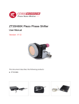
3.Driving Principle
Contro l
way
Analog
input
Power
Sensor servo
control
Sensor signal input
Sensor output
Offset adjustment
High voltage output
Open loop
Servo

4
E51.D12S Series Piezo Controller User Manual
5.Installation
E51.D12S controller has been carefully checked for electrical and mechanical aspects before
shipment. When you receive the device, unpack and inspect the surface of the system for any
obvious signs of damage. If it is damaged, it may be damaged during transportation, please
contact our customer service department in time. Check whether the accessories are complete
according to the packing list. Please keep the original packaging materials for subsequent
maintenance and using.
5.1 Installation Precautions
Note! Improper installation of the E51.D12S series piezo controller may cause personal injury or
damage the E51.D12S series piezo controller!
Installation and using of E51.D12S should be close to the power source, so that the power
plug can be easily and quickly disconnected from the main power source.
Use included power cord to connect E51.D12S series piezo controller system.
If power cord provided by our company must be replaced, please use power cord with
large enough size and effective grounding.
5.2 Ensure Ventilation
Note! Overheating of equipment due to high temperature may damage the E51.D12S controller!
Ensure that the cooling area of the controller is sufficiently cooled.
Ensure that there is adequate ventilation equipment.
Keep ambient temperature to non-critical level(<50℃ ).
Temperature of cooling surface of controller>50 ℃ , it is recommended to take external
heat dissipation measures to improve the stability of the controller.
5.3 Connect power
Use power adapter to connect to power supply interface of the E51.D12S power supply.
5.4 Cable Connection
When the power supply is disconnected, the swing mirror cable is connected to the
4.Checking

5
6. Appearance
6.1 Front Panel
6.2 Rear Panel
E51.When the power supply is disconnected, connect the PZT&Sensor cable to the E51.D12S
controller interface. Note that the number on the piezo actuator corresponds to the number of
the controller.
Connect to the computer control mode of PC, connect to PC through the cable connection
USB interface or RS-232/422 interface socket.
Symbol Function Description
POWER Latching switch Power switch. Press power to turn on the green light.
Power off, lights off.
Symbol Function Description
CH1-CH6 DB15-HD Mirror connection
24V DC DC-044B-J( 2.5) Power connector socket.Connect through a power
adapter or a DC power supply.
RS-422 D-SUB 9 hole
socket
The computer is connected with the controller interface
module through RS-422 port access terminal to realize
computer control.

6
E51.D12S Series Piezo Controller User Manual
DB15-HD interface(Drive output and sensor connector)
RS-422 interface
No. Pin definition No. Pin definition
1 CH2 drive output 9Sensing power supply ground
2 CH3 drive output 10 Sensing power supply ground
3 CH3 sensor input signal - 11 Constant voltage drive output
4CH3 sensor input signal + 12 CH2 sensor input signal -
5 Sensor power supply: DC 10V 13 CH2 sensor input signal +
6CH1 drive output 14 CH1 sensor input signal +
7Drive output ground 15 CH1 sensor input signal -
8 Sensor power supply: DC 10V
6.3 Interface
No. Pin definition
1
2
3
4
5 GND
6RS-422 RxD+
7RS-422 RxD-
8RS-422 TxD-
9RS-422 TxD+

7
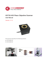
● Average output(Sine wave operation mode)
Pa ≈ Upp • Us • f• Cpiezo
Pa=Average output[W]
Upp=Peak and peak drive voltage [V]
Us=Drive voltage[V]((Vs+)-(Vs-))
Cpiezo=Piezo actuator capacitance[F]
f=Operating frequency of the sine wave[Hz]
7.Operating Calculation
8.1 Cleaning measures
Note! The PCB board of the function module in the E51.D12Ssystem is an ESD (electrostatic
discharge) sensitive device. Take precautions against any static build-up of these devices before
use to avoid contact with circuit component leads and PCB wiring. Before touching any electronic
components, the body rst touches the grounding conductor to discharge static electricity, ensuring
that any type of conductive particles (metal, dust or debris, pencil lead, screws) enter the device.
Be careful not to drop the equipment when cleaning, to avoid any form of mechanical shock!
Disconnect the power plug of the E51.D12S system before cleaning.
8. Maintenance, Storage, Transportation
20
80
60
40
140
120
100
0 10 1000100
0.1μf
0.3μf
1μf
1.8μf
3.6μf
7.2μf
14μf
25μf
Frequency vs Voltage
Frequency(Hz)
Output voltage(V)

8
E51.D12S Series Piezo Controller User Manual
Prevent cleaning fluid and any liquid from entering the system module to avoid short
circuits.
The surface of the system chassis and the front panel of the module, please do not use an
organic solvent for surface wiping.
8.2 Transportation and Storage
This product is packed in carton. Transportation must be carried out under product
packaging conditions, and direct rain and snow, direct contact with corrosive gases and strong
vibrations should be avoided during transportation.
The instrument can be transported under various conditions of normal transportation, and
should avoid damp, load, collision, extrusion, irregular placement and other adverse conditions
during transportation.
If the instrument is not used for a long time, the instrument should be packaged and
stored.
The instrument should be stored in a non-corrosive atmosphere and in a well ventilated,
clean room.
In the process of transportation, storage and use, attention should be paid to fire
prevention, shockproof, waterproof and moisture proof.
9.1 Disposal
When disposing of old equipment, please abide by the national regulations and local
regulations.Please dispose of the old equipment properly.Please contact CoreMorrow for the
upgrade and replacement of old equipment in order to meet the customer's handling of system
products.
If you have an old device or an unusable device that cannot be handled, you can ship it to
the following address:
Address: 1F, Building I2, No.191 Xuefu Road, Nangang District, Harbin, Heilongjiang
9.Service and Maintenance

9
10.Contact us
Harbin Core Tomorrow Science & Technology Co., Ltd.
Tel: +86-451-86268790
Email: info@coremorrow.com
Website: www.coremorrow.com
Address: Building I2, No.191 Xuefu Road, Nangang District, Harbin, HLJ, China
CoreMorrow Official and CTO WeChat are below:
9.2 After-sales Service
E51.D12S does not contain user repairable components.
E51.D12S must be returned to factory for any service and repair.
Any part of E51.D12S is dismantled, there will be no warranty service.
E51.D12S is a precision instrument which should be handled with care.
In case of any problem, please record the problem and contact CoreMorrow to be repaired
by professional technicians.
-
 1
1
-
 2
2
-
 3
3
-
 4
4
-
 5
5
-
 6
6
-
 7
7
-
 8
8
-
 9
9
-
 10
10
-
 11
11


Ask a question and I''ll find the answer in the document
Finding information in a document is now easier with AI
Related papers
-
Coremorrow 40A5 User manual
-
 Coremorrow ZT35H80K User manual
-
 Coremorrow XD304-B1 User manual
-
 Coremorrow Modular E70 Series Piezo Controller User manual
-
 Coremorrow T50N81K13 User manual
-
 Coremorrow XD730.400 User manual
-
Coremorrow E70 Series User manual
-
Coremorrow E51.D7S Series User manual
-
Coremorrow S51.ZT1S/K-C1 Piezo Z/Tip/Tilt Platform User manual
-
Coremorrow E52 Series User manual


Other documents
-
Huawei OptiX OSN 2500 Quick Installation Manual
-
Nikon MB-12 User manual
-
Infinity 1210a User manual
-
D&B D12 Hardware Owner's manual
-
Kawasaki E5 Series Installation And Connection Manual
-
Sony HCD-DX30 User manual
-
Delta Tau TURBO PMAC PCI LITE User manual
-
-
-