Blackmagicdesign Fairlight 5 Bay Assembly Manual
- Category
- Supplementary music equipment
- Type
- Assembly Manual
This manual is also suitable for
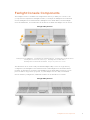
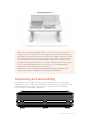
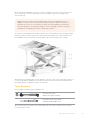
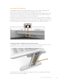
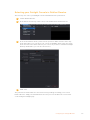
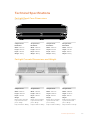
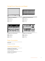
Blackmagicdesign Fairlight 5 Bay is a professional audio console designed for high-end audio post production. With its modular design, you can customize your console with the Fairlight modules you need, including channel controls, faders, audio editors, and LCD monitors. The Fairlight 5 Bay console offers precise handling and finesse, with illuminated buttons and easy-to-read LCDs for monitoring your settings. The servo-assisted faders can be saved and recalled, maintaining sync with DaVinci Resolve. Experience real-time adjustments to your audio mix with the responsive faders.
Blackmagicdesign Fairlight 5 Bay is a professional audio console designed for high-end audio post production. With its modular design, you can customize your console with the Fairlight modules you need, including channel controls, faders, audio editors, and LCD monitors. The Fairlight 5 Bay console offers precise handling and finesse, with illuminated buttons and easy-to-read LCDs for monitoring your settings. The servo-assisted faders can be saved and recalled, maintaining sync with DaVinci Resolve. Experience real-time adjustments to your audio mix with the responsive faders.


-
 1
1
-
 2
2
-
 3
3
-
 4
4
-
 5
5
-
 6
6
-
 7
7
-
 8
8
-
 9
9
-
 10
10
-
 11
11
-
 12
12
-
 13
13
-
 14
14
-
 15
15
-
 16
16
-
 17
17
-
 18
18
-
 19
19
-
 20
20
-
 21
21
-
 22
22
-
 23
23
-
 24
24
-
 25
25
-
 26
26
-
 27
27
-
 28
28


Blackmagicdesign Fairlight 5 Bay Assembly Manual
- Category
- Supplementary music equipment
- Type
- Assembly Manual
- This manual is also suitable for
Blackmagicdesign Fairlight 5 Bay is a professional audio console designed for high-end audio post production. With its modular design, you can customize your console with the Fairlight modules you need, including channel controls, faders, audio editors, and LCD monitors. The Fairlight 5 Bay console offers precise handling and finesse, with illuminated buttons and easy-to-read LCDs for monitoring your settings. The servo-assisted faders can be saved and recalled, maintaining sync with DaVinci Resolve. Experience real-time adjustments to your audio mix with the responsive faders.
Ask a question and I''ll find the answer in the document
Finding information in a document is now easier with AI
Related papers
Other documents
-
Blackmagic DaVinci Resolve 17 New Features User guide
-
-
-
-
-
-
-
 Blackmagic Design HyperDeck Studio Mini Owner's manual
-
-
ENHANCED VISION DaVinci HD User manual
