
VIADRUS HERCULES Green Eco Therm
Manual for boiler operation and installation
GB_2015_11

2
Contents:
page
1.
Produced variants of boiler .......................................................................................................................... 3
2.
Technical data of the boiler ......................................................................................................................... 4
3.
Boiler description ......................................................................................................................................... 6
3.1
Boiler drum construction ..................................................................................................................... 6
3.2
Control, regulation and safety elements ............................................................................................. 6
3.2
The construction of burner and transport routes of the fuel ................................................................ 9
4.
Location and installation ............................................................................................................................ 11
4.1
Regulations and directives ................................................................................................................ 11
4.2
Positioning possibilities ..................................................................................................................... 12
5.
Order, delivery and assembly .................................................................................................................... 14
5.1
Order ................................................................................................................................................. 14
5.2
Delivery and accessories .................................................................................................................. 14
5.3
Assembly procedure ......................................................................................................................... 16
5.3.1
Boiler drum installation .................................................................................................................. 16
5.3.2
Mounting of partitions of the combustion chamber and turbulators .............................................. 17
5.3.3
Mounting of burner ........................................................................................................................ 17
5.3.4
Mounting of the fuel reservoir ....................................................................................................... 19
5.3.5
Mounting of the shells ................................................................................................................... 20
5.3.6
Installation of electrical wiring ....................................................................................................... 21
5.3.6.1
Version VIADRUS HERCULES Green Eco Therm XJ ......................................................... 21
5.3.6.1
Version VIADRUS HERCULES Green Eco Therm XS ......................................................... 22
5.3.7
Assembly tools for brush............................................................................................................... 22
5.3.8
Filling of the heat system with water ............................................................................................. 22
5.3.9
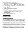
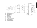
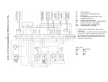
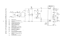
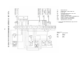
Electrical scheme .......................................................................................................................... 23
5.3.10
Boiler hydraulic diagram ............................................................................................................... 27
6.
Putting into operation - instructions for contractual service organization .................................................. 28
6.1
Inspections before start-up ............................................................................................................... 28
6.2
Boiler putting into operation .............................................................................................................. 28
7.
Boiler operation by user ............................................................................................................................. 29
7.1
Version VIADRUS HERCULES Green Eco Therm XJ ..................................................................... 29
7.1.1
Setting of the heat output of burner .............................................................................................. 31
7.2
Version VIADRUS HERCULES Green Eco Therm XS..................................................................... 35
7.2.1
Setting of the heat output of burner .............................................................................................. 37
8.
IMPORTANT WARNINGS ........................................................................................................................ 40
9.
Maintenance .............................................................................................................................................. 41
10.
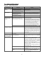
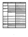
Faults and their removal ........................................................................................................................ 43
11.
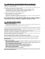
Instructions for product liquidation after its operating life ....................................................................... 45
12.
Warranty and defect liability ................................................................................................................... 45

3
Dear customer,
thank you for the purchase of VIADRUS HERCULES Green Eco Therm boiler; this purchase
demonstrates your confidence in VIADRUS a.s.
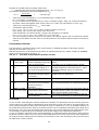
In order to get used to a proper treatment of your new product from the start please read these
instructions for its use (first of all the chapter no. 7 – Boiler attendance by user, chapter
no. 11 – Important warnings and chapter no. 12 – Maintenance by user). Please observe the
information given below in order to ensure a longstanding trouble-free operation of boiler so that
both you and we are satisfied.
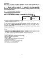
1. Produced variants of boiler
•
Order specification code
VIADRUS HERCULES Green Eco Therm X X
The fuel tank is included in the standard boiler accessories
•
Optional accessories (see chapter no. 5.2)
The boiler design you received is only destined for wooden pellets combustion (specification see page 4)
and its trade name is VIADRUS HERCULES Green Eco Therm. It is the boiler with automatic fuel supply.
The burner is cleaned manually.
The boiler is manufactured as warm-water boiler with forced heating water circulation and working
overpressure up to 400 kPa (4 bar). The boiler is tested for tightness by applying 800 kPa (8 bar)
overpressure before despatch.
The use:
The version of boiler VIADRUS HERCULES Green Eco Therm 25X is particularly destined for heating
of individual housing units, weekend houses, cottages etc.
The version of boiler VIADRUS HERCULES Green Eco Therm 32X is particularly destined for heating
of cottages, weekend houses, small business premises, smaller leisure amenities etc.
Advantages of boiler:
automatic boiler operation guarantees the heating comfort,
mechanical fuel feed from any reservoir
automatic ignition
simple, not time-consuming attendance and maintenance
high efficiency reaching 87,9 %,
boiler drum construction proven on a long-term basis
high service life of the cast iron boiler drum
five-year guarantee for the boiler drum
Type of burner:
J: Junior
S: Senior
Burner output:
25: 25 kW
32: 32 kW

4
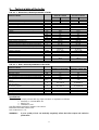
2. Technical data of the boiler
Tab. no. 1 Dimensions, thermal parameters of boiler
Version of boiler VIADRUS HERCULES
Green Eco Therm VIADRUS HERCULES
Green Eco Therm
25S 25J 32S 32J
Section number pcs 5 7
Class of boiler according to EN 303-5 - 4 3 3 4
Weight including the supplied fuel tank kg 332 401
Fuel tank weight on demand kg 65 65
Water space volume l 40,9 50,3
Diameter of smoke socket mm 156 156
Boiler dimensions (incl. burner): - height x width mm 1218 x 1309 1218 x 1309
- depth mm 1335 1527
Capacity of the supplied fuel tank dm
3
130 130
kg 85 85
Fuel tank capacity on demand dm
3
725 725
kg 470 470
Water operating overpressure kPa (bar) 400 (4) 400 (4)
Testing water overpressure kPa (bar) 800 (8) 800 (8)
Hydraulic loss (∆T 20 K) Pa 80 110
Recommended heat water operating temperature °C 60 - 80 60 - 80
Recommended return water operating temperature
°C 60 60
Noise level dB Doesn´t exceed level
65 dB (A) Doesn´t exceed level
65 dB (A)
Chimney draught mbar 0,15 - 0,25 0,20 - 0,30
Boiler connections - heat water G 1 1/2" G 1 1/2"
- return water G 1 1/2" G 1 1/2"
Connected voltage 1/N/PE 230 V AC 50 Hz
TN-S 1/N/PE 230 V AC 50 Hz
TN-S
Operating electric power/max.
W 100/1200 100/1200
Electric protection IP 20 IP 20
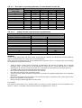
Tab. no. 2 Heat - technical parameters of the boiler
Version of boiler VIADRUS HERCULES
Green Eco Therm 25X VIADRUS HERCULES
Green Eco Therm 32X
Section number pcs 5 7
Nominal output kW 25 32
Minimum output kW 7,5 9,6
Efficiency % up to 86,8 up to 87,9
The approximate fuel consumption at rated output kg.h
-
1
5,8 8,2
The approximate fuel consumption at minimum
output kg.h-1 1,74 2,45
Burning time at nominal output - supplied tank / the
tank by request. h 14,17/78,33 10,625/58,75
Burning time at minimum output - supplied tank /
the tank by request h 60,7/335,71 35,42/195,83
Heating value MJ. kg
-
1
17,189 17,189
Flue gas temperature °C 120 - 210 120 - 210
Flue gases mass flow rate at nominal output kg.s
-
1
0,018 0,021
Flue gases mass flow rate at minimum output kg.s
-
1
0,009 0,014
Specified fuel:
The pellets must comply at least with one of the standards or regulations as follows:
Direction no. 14-2000 MŽP ČR
DIN 517 31
ÖNORM M 7135
Specified pellets granularity: between 6 and 8 mm
Maximum fuel water content. 12%.
Ash content max. 1,5 %
WARNING! A poor quality of fuel can markedly negatively affect the boiler output and emission
parameters.

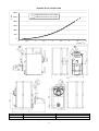
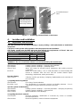
5
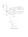
Hydraulic losses of boiler drum
0
500
1000
1500
2000
2500
3000
0 0,5 1 1,5 2 2,5 3 3,5 4
HERCULES Green Eco Therm 25X
HERCULES Green Eco Therm 32X
Q [dm
3.
s
-1
]
p
z
[Pa]
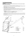
Version of boiler VIADRUS HERCULES Green Eco Therm 25X VIADRUS HERCULES Green Eco Therm 32X
L 1335 1527
L1 809 1001
Fig. no. 1 Boiler dimensions

6
3. Boiler description
3.1 Boiler drum construction
The cast iron section boiler drum is the main part of boiler and it is manufactured of grey cast iron according
to EN 1561
•
central sections – quality 150 (previously ČSN 42 2415)
•
front and rear sections – quality 200 (previously ČSN 42 2420)
The pressure parts of boiler conform to the strength requirements according to EN 303-5.
The boiler drum is assembled of sections by means of pressed on boiler insertions and secured by means of
anchor bolts. The sections create the combustion and ash-pan space, the water space and convection part.
The inlet and outlet of heating water are situated in the rear part of boiler.
The rear section of boiler in its upper part has a smoke extension piece and heating water flange, in the lower
part there is the return water flange with a sleeve piece for inlet and outlet cocks. The cleaning door and ash
door with mounted burner are affixed to the front boiler section.
The whole boiler drum is insulated by means of a health harmless mineral insulation which reduces the
losses caused by the heat transfer into ambient. The steel shell colour is treated by means of high-quality
komaxit spray.
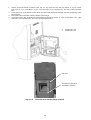
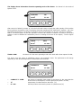
3.2 Control, regulation and safety elements
Elements for control, regulation and safety placed in the control cabinet
Thermomanometer serves for measuring the temperature and pressure of water in the heating system and
is located in the upper part of the boiler shell. The check valve for pressure gauge connection is located in the
upper part of the rear boiler section.
Operating thermostat switches off / switches on the operation of the burner according to the set
temperature of heating water.
Signalling of safety thermostat signals the activation of the safety thermostat (overheating of the heating
system above 97 °C)
The safety thermostat is placed in the control box and serves for ensuring the heating system against
overheating. This thermostat is set by the manufacturer to a temperature of 95°C, i.e. to a higher temperature
than can be set as the desired temperature on the boiler. When you turn off the safety thermostat unblocking
must be done manually. The safety thermostat can be turned on only after the temperature has dropped
below the set value. We have to unscrew the black cap of the safety thermostat and by using a suitable
object we press the button.
In case of repeated switching of the thermostat the boiler must be shut down and the reason of repeated
overheating of the boiler must be found out.
The thermostat of the pump switches on and switches off the pump of heating water according to the set
temperature.
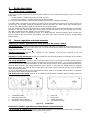
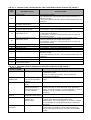
1. Termomanometer
2. Operating thermostat
3. The switch "start of burner"
4. Signalling of safety thermostat
5. Fuse 10A
6. Main switch
7. Safety thermostat
8. Thermostat of pump
Fig. no. 2 Control box
Elements for control, regulation and safety placed on the boiler body
The air rosette of cleaning door and the lower stifling element is not used at the boiler with an automatic
combustion of wooden pellets and must be permanently closed.

7
Elements for control, regulation and safety placed on the burner
•
Control Module of boiler (version VIADRUS HERCULES Green Eco Therm XJ) or automatic (version
VIADRUS HERCULES Green Eco Therm XS).
•
LCD display with control buttons, that is designed for change of the values of operating parameters
(version VIADRUS HERCULES Green Eco Therm XJ).
•
Potentiometer – for setting the boiler output (version VIADRUS HERCULES Green Eco Therm XS).
•
Photo sensor, which monitors the intensity of the combustion process.
•
Transport hose with reinforcing spiral, which melts in the case of penetration of fuel back through the
knee of burner, thus preventing further supply of pellets into the burner.
•
Sensor of penetration of fuel (TD) is placed on the knee of burner and is activated in case of the
surface temperature above 90 °C. Burner and fuel feeder are stopped in case of activation of this sensor
and the system is switched over into reporting of a failure. The failure mode is deactivated by switching
off and on of the main switch. It is necessary to determine the cause of the failure and take appropriate
measures, namely before restarting of the burner;
•
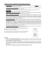
Reversible thermal label displays the operating temperature of the burner body. This temperature is an
indicator for operating mode of the burner and temperature of flue gases which pass the combustion
chamber back into the fuel tank. The initial state is shown in black colour for all thermally active parts. If
the temperature is increased, the segments gradually are getting a light colour, according to the
temperature range of individual heat-active segments. The reversible thermal label should be checked
as needed. Increased temperature in this section signals the necessity to clean the boiler, grate of
burner or routes of flue gasses and smoke flue. During cooling of the main burner body the colour of the
label returns to its original state (all segments are black).
•
Irreversible thermal label displays overheating of the knee of burner. This label in case exceeding of
temperature of the burner knee irreversibly changes its colour.
The initial status, the active segment is white, the temperature hasn’t
reached the degree of activation 104 °C;
The status at activation, the active segment is dark, the temperature
has exceeded the degree for activation 104 °C; activation of 104 °C;
°C
104 °F
219
THERMAX
°C
104 °F
219
THERMAX
CAUTION:
• Activation of irreversible thermal label is signalling overheating of the knee of burner. Status of this
label is irreversible and in case of damage it has to be replaced. Control and service of burner may be
performed only by an authorized technician.
• This thermal label is activated for example when hot combustion products pass back via the fuel feeder
due to an increased resistance of the smoke flue or a lower draft in the chimney. In such cases the
transport hose that connects the fuel feeder and burner body can be damaged and will be necessary its
replacement.
• In case of these emergency statuses the warranty for the burner is void.

8
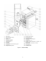
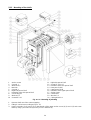
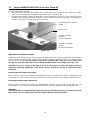
1. Boiler drum
2. Boiler shell with ashtray
3. Cleaning door
4. Burner
5. Transitionary flange
6. Insulation of burner
7. The ash door
8. Fuel tank
9. Fuel feeder
10. Transport hose with reinforcing spiral
11. Control box
12. Flange of heating water
13. Flange of return water
14. Fill and drain cock
15. Sealing 90 x 60 x 3
16. Assembly of smoke adapter
17. Turbulators
18. Partition of flue way
19. Partition of the combustion chamber- the
front section
20. Partition of the combustion chamber
21. Hose clamp
22. Screw M10 x 50
23. Screw M10 x 30
Fig. no. 3 Boiler assembly

9
3.2 The construction of burner and transport routes of the fuel
The version VIADRUS HERCULES Green Eco Therm XJ
• Control module with microprocessor;
• LCD display with control buttons, that is designed for change of the values of operating parameters;
Version VIADRUS HERCULES Green Eco Therm XS
• Control panel on which there is placed a potentiometer for setting the boiler output;
• Colour scale on which we can set the position of throttle flap of the fan (the output power of fan) to the
same colour as the setting of the thermal output potentiometer.
• Manual setting of throttle flap of the fan.
Version of boiler VIADRUS HERCULES Green Eco Therm
25J 25S 32J 32S
Nominal heat output 25 25 32 32
power range 7,5 - 25 7,5 - 25 9,6 - 32 9,6 - 32
The burner consists of following components:
• Combustion chamber, which serves for burning pellets and made from high quality stainless steel;
• Removable grate of combustion chamber;
• Electric spiral, by means of which the fuel is ignited. It is located behind the inclined plate of grate in the
combustion chamber;
• Fan for intake of air, equipped with Hall effect sensor for sensing the rotational speed;
• Photo sensor, which monitors the intensity of the combustion process;
• Sensor for penetration of burning fuel (TD) which stops the operation of the burner in case of break
forth of flame into the fuel feeder;
• Socket for connecting the fuel feeder, which ensures power supply into the motor of the fuel feeder;
• Reversible thermal label from a liquid crystal with the indicator of current temperature of the
body of burner.
• Irreversible thermal label from a liquid crystal which signals the high temperature of the knee of
burner, preliminarily sets the conditions for the non-warranty service of the main module of burner and of
any kind of damage to the hose for fuel supply;
• Fuel feeder with an inlet cable and 1 ~ plug.
• Transport hose with reinforcing spiral, which is made partly of a transparent heat-resistant material
(in case of burning does not emit toxic substances and does not maintain the process of burning), that
interconnects the fuel feeder and the knee of burner;
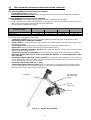
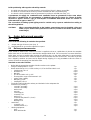
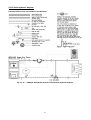
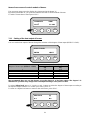
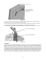
Fig. no. 4 Burner and fuel feeder
Fuel feeder
Transport hose
with reinforcing
spiral
Burner
Knee of
the burner

10
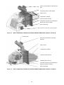
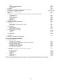
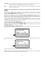
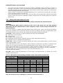
Fig. no. 5 Basic components of the burner of boiler VIADRUS HERCULES Green Eco Therm XJ
Fig. no. 6 Basic components of the burner of boiler VIADRUS HERCULES Green Eco Therm XS
Sensor for penetration of burning fuel
(TD)
LCD display with control buttons
Photo sensor
Combustion chamber
Control module of boiler
Transitionary flange for mounting the
burner to the door of boiler
Inlet of electricity
Socket for connection of the fuel feeder
Sensor for penetration of burning
fuel (TD)
Photo sensor
Combustion chamber
Control module of boiler
Throttling flap of the fan
Transitionary flange for mounting the
burner to the door of boiler
Inlet of electricity
Control panel

11
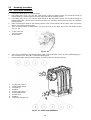
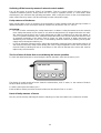
Fig. no. 7 Positioning of thermal labels on the burner
4. Location and installation
4.1 Regulations and directives
The solid fuel boiler can only by mounted by a company holding a valid authorization to install these
equipments.
A project according to the valid regulations must be prepared for the installation.
The heating system must be filled with water that matches the requirements of ČSN 07 7401 and
especially its hardness must not exceed the required parameters.
Recommended values
Hardness mmol/l 1
Ca
2+
mmol/l 0,3
Concentration of total Fe + Mn mg/l (0,3)*
*) Recommended value
WARNING!!! The use of anti-freeze mixture is not recommended by the manufacturer.
a) to the heating system
ČSN 06 0310 Heating systems in buildings – Designing and installation
ČSN 06 0830 Heating systems in buildings – protecting device
ČSN 07 7401 Water and steam for thermal energy equipments with working pressure
up to 8 MPa.
EN 303-5 Boilers for central heating – Part 5: Solid fuel boilers for central heating with
manual or automatic feed and max. 500 kW nominal thermal output:
terminology, requirements, testing and marking.
b) to the chimney
ČSN 73 4201 Chimneys and flue gas ducting– designing, implementation and connection of
fuel consumers.
c) regarding the fire regulations
ČSN 06 1008 Fire safety of heat installations.
EN 13501-1 +A1 Fire classification of construction products and building elements – Part 1:
Classification using test data from reaction to fire tests
d) to the system of HWS heating
ČSN 06 0320 Heating systems in buildings – Hot water preparation – Designing and planning
ČSN 06 0830 Heating systems in buildings – Safety devices.
ČSN 75 5409 Water installations inside buildings.
e) regarding the electric network
CSN 33 0165 Electrical regulations. Identification of conductors by colours or numerals.
Procedure provisions
ČSN 33 1500 Electrical regulations; revision of electrical equipments
Reversible thermal
label with indicator of
current temperature
of the body of burner
Irreversible thermal
label

12
ČSN 33 2000-1 ed. 2 Low-voltage electrical installations – Part 1: Fundamental principles,
assessment of general characteristics, definitions.
ČSN 33 2000-4-41 ed. 2 Low voltage electrical installations - Part 4-
41: Protection for safety -
Protection against electric shock
ČSN 33 2000-5-51 ed. 3 Electrical installations of buildings – Part 5-51: Selection and erection of
electrical equipment – Common rules
ČSN 33 2130 ed. 2 Low-voltage electrical installations – Internal electric distribution lines
ČSN 33 2180 Electrical regulations: Connection of electric instruments and appliances
ČSN 34 0350 ed. 2 Safety requirements for flexibile cords and cables
EN 60079-10-1 Explosive atmospheres — Part 10-1: Classification of areas — Explosive gas
atmospheres
EN 60079-14 ed.3 Explosive atmospheres - Part 14: Electrical installations design, selection and
erection
EN 60252-1 ed. 2 Capacitors for AC motors – Part 1: In general – Design, testing, dimensioning
– Safety requirements – Instructions for installation and operation.
EN 60 335-1 ed.2 Electric appliances for household and similar purposes – Safety – Part 1:
General requirements
EN 60 335-2-102 Electric appliances for household and similar purposes – Safety – Part 2-102:
Special demands on appliances containing the electric connections and
burning the gas, oil and solid fuels
EN 60445 ed. 4 Basic and safety principles for man-machine interface, marking and
identification – Identification of equipment terminals, conductor terminations
and conductors
EN 61000-6-3 ed. 2 Electromagnetic compatibility (EMC) - Part 6-3: Generic standards – Emission
standard for residential, commercial and and light industrial environments
EN 61000-3-2 ed. 3 Electromagnetic compatibility (EMC) - Part 3-2: Limits - Limits for harmonic
current emissions (equipment input current ≤16 A per phase)
EN 61000-3-3 ed. 2 (ed. 3) Electromagnetic compatibility (EMC) - Part 3-3: Limits - Limitation of voltage
changes, voltage fluctuations and flicker in public low-voltage supply systems,
for equipment with rated current ≤16 A per phase and not subject to
conditional connection.
4.2 Positioning possibilities
Boiler positioning in the living space (including corridors) is prohibited!
The installation of the boiler must comply with all requirements of ČSN 06 1008.
ATTENTION!
In the event that it is installed the delivered wooden fuel reservoir, then it is necessary to install a
fireproof bulkhead between the reservoir and boiler.
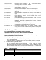
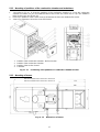
Boiler placing with regard to fire regulations:
1. Placing on floor of flame resistant material (Fig. no. 8)
- boiler to be put on a flame resistant backing exceeding the boiler platform over 20 mm at sides and
only on the boiler drum depth.
- if the boiler is situated in a cellar we recommend to place it on a bedding of minimum 50 mm height.
2. A safe distance from the combustible materials:
- when installing and operating the boiler it is necessary to keep a safety distance of 200 mm from the
materials of combustibility grade A1, A2, B and C (D);
- for easily combustible materials of combustibility grade E (F), which quickly burn and burn
themselves even after removal of ignition source (such as paper, cardboard, asphalt and tar paper,
wood and wood-fiber boards, plastics, floor coverings) the safe distance has to be doubled, i.e. to
400 mm;
- safe distance should be doubled as bulb where the grade of reaction to fire has not been proved.
Tab. no. 3 Grade of reaction to fire
Grade of reaction to fire Examples of building materials and products included in the reaction to fire
(Extract from EN 13 501-1 + A1)
A1 – incombustible Granite, sandstone, concrete, bricpcs, ceramic tiles, mortars, fireproof plasters, …
A2 – combustible with difficulty
acumin, izumin, heraklit, lignos, boards and basalt felt, fibreglass boards,...
B – hardly combustible Beech and oak wood, hobrex boards, plywood, werzalit, umakart, sirkolit,...
C (D) – medium combustible Pinewood, larch, whitewood, chipboard and cork boards, rubber flooring,...
E (F) – easily combustible Asphaltboard, fibreboards, cellulose materials, polyurethane, polystyrene,
polyethylene, PVC,…

13
Section number
5 7
L [mm] 680 872
Fig. no. 8 Bedding dimensions
The boiler placing with respect to the necessary handling space:
•
basic surroundings of AA5/AB5 according to ČSN 33 2000-1 ed. 2;
•
handling space of minimum 1000 mm in front of the boiler must be maintained;
•
a minimum distance of 400 mm between the back part of the boiler and the wall;
•
from the side of the boiler there must be maintained a space at least 500 mm for the door opening and
for the access to the rear part of the boiler;
•
a minimum distance of 100 mm from the side wall.
•
a minimum boiler-room height 2 100 mm
Fig. no. 9 Boiler placing in a boiler room
Fuel placing:
•
dry fuel (up to the 12% moisture) must be used in order to guarantee the correct combustion in the
boiler. The pellets should be stored in their original packing from the manufacturer
(e.g. PET sacpcs) at a dry place;
•
it is impossible to store fuel behind the boiler or unload it next to the boiler in a distance smaller than
400 mm;
•
the manufacturer recommends that min. 1000 distance is kept between the boiler and fuel or the fuel is
placed in a room different from that where the boiler is installed

14
Boiler positioning with regard to electricity network:
•
the boiler must be placed so that the plug in socket (230 V/50 Hz) is always accessible;
•
the boiler is connected to the mains by a fixed movable inlet with a normalized plug;
•
the electric shock prevention must be guaranteed according to valid EN (see chap. 4.1.)
A permanent air supply for combustion and ventilation must be guaranteed in the room where
the boiler is installed (the air consumption of VIADRUS HERCULES Green Eco Therm 5X boiler
amounts to approx. 80 m
3
.h
-1
, the air consumption of VIADRUS HERCULES Green Eco Therm 7X
boiler amounts to approx. 160 m
3
.h
-1
.
The connection of heating system piping must be carried out by a person authorised according to
the valid regulations.
.
CAUTION: When connecting the boiler to the heating system there must be installed a inlet and
outlet cocpcs in the lowest point and as near as possible to the boiler (at the return
water flange).
5. Order, delivery and assembly
5.1 Order
In the order the following is needed to be specified:
1. Output and type of burner (see chap. 1)
2. Requirements for accessories offered on request
5.2 Delivery and accessories
Boiler VIADRUS HERCULES Green Eco Therm is supplied so that on a pallet there is placed the complete
boiler drum and on the side there is attached the wrapped boiler shell. The accessories are stored inside the
boiler drum and are accessible after opening the cleaning door. On the other pallet there is stored wooden
fuel container, in which there is stored the burner, the fuel feeder and their accessories. The boiler is packed
into a shipping container and must not be flipped during shipping; it is only permitted to tilt to the sides in
order to remove the wrapping from the boiler drum.
Standard accessories to boiler:
•
Boiler with the appropriate number of boiler sections on the palette
•
Flange of heating water G 1 1/2" 1 pc
•
Return water flange G 1 1/2 "with socket Js 1/2" for the fill and drain cock 1 pc
•
Sealing φ 90 x 60 x 3 2 pcs
•
Washer 10,5 8 pcs
•
Nut M10 8 pcs
•
The fill and drain cock Js 1/2“ 1 pc
•
Three-position sump of thermostat G 1/2" 1 pc
•
spring of the capillary 1 pc
•
Blind plug Js 6/4“ 1 pc
•
Sealing 60 x 48 x 2 1 pc
•
The boiler shell including the ashtray and insulation in the adequate size
•
Fasteners for jacketing
-
console 1 assembly 2 pcs
-
console 2 assembly 2 pcs
-
washer 10,5 4 pcs
-
nut M10 4 pcs
-
connecting pin 4 pcs
-
screw M5 x 12 4 pcs
-
washer 5,3 4 pcs
-
screw into the plate ST 4,2 x 9,5 6 pcs
-
spring clamp 4 pcs
-
bushing PG 9 7 pcs
•
control box 1 pc
-
screw M5 x 12 4 pcs
-
serrated washer 5,3 4 pcs
•
cleaning equipment
-
hook 1 pc
-
brush with handle 1 pc

15
-
pike 1 pc
-
cleaning equipment holder 1 pcs
-
handling key 1 pc
•
turbulator 4 pcs
•
partition of combustion chamber – the front segment 1 pc
•
the partition of combustion chamber 4 pcs - 7 sect.
•
the partition of smoke channel 2 pcs
•
burner 1 pc
•
fasteners for mounting of burner and for mounting of a transitionary flange
-
screw M10 x 50 3 pcs
-
screw M10 x 30 3 pcs
-
spring washer 10 6 pcs
-
washer 10,5 6 pcs
-
nut M10 6 pcs
•
insulation of burner 1 pc
•
transitionary flange of the burner 1 pc
•
fuel feeder 1 pc
-
transport hose with reinforcing spiral 1 pc
-
hose clamp 2 pcs
•
fuel reservoir 1 pc
-
sloping bottom 2 pcs
-
flange of the fuel feeder 1 pc
•
fasteners for the fuel reservoir
-
screw M8 10 pcs
-
nut M8 10 pcs
-
washer 8,4 10 pcs
•
flexo cord 5 m 1 pc
•
boiler label 1 pc
•
business – technical documentation
Accessories delivered by request:
•
fuel reservoir 725 l
- the side of fuel reservoir 3 pcs
- the side of fuel reservoir with the hole for spiral worm 1 pc
- the foot of fuel reservoir 4 pcs
- the bottom of fuel reservoir 2 pcs
- the bottom of fuel reservoir A 2 pcs
- the cover of fuel reservoir 1 pc
- handle 1 pc
•
connection accessories for fuel reservoir assembly
- pendant chainlet 1 pcs
- screw M6 x 12 72 pcs
- washer 6,4 72 pcs
- nut M6 72 pcs
- screw M6 x 16 2 pcs
- washer 8,4 2 pcs
The boiler equipment delivered “by request“ is not included in the basic price of boiler

16
5.3 Assembly procedure
5.3.1 Boiler drum installation
1. Position the boiler body on a retaining wall.
2. Put sealing 90 x 60 x 3 (1) onto the upper flange of the rear boiler section and screw the flange of
heating water (2) and then interconnect the other end with the heating system.
3. Put sealing 90 x 60 x 3 (5) onto the lower flange of the rear boiler section and screw the flange of
heating water with a sleeve (6) for the fill and drain cock and then interconnect the other end with the
heating system.
4. After connecting the boiler to the heating system screw a knee with the fill and drain valve (9) into the
sleeve of the flange of return water.
5. Then screw the sump of thermostat G 1/2 "into the hole in the upper part of the rear boiler section
(Fig. no. 10).
Fig. no. 10
6. Then carry out blinding of the threaded hole Js 6/4 "in the front boiler section by using a blinding plug Js
6/4". Place the seal 60 x 48 x 2 under the blinding plug.
7. Fit the smoke pipe onto the smoke adapter and insert it into the chimney opening.
Fig. no. 11 Boiler drum installation
1 Check valve for
the manometer
2 Boiler basin
1. Sealing φ 90 x 60 x 3
2. Heating water flange
3. Washer10,5
4. Nut M10
5. Sealing φ 90 x 60 x 3
6. Return water flange
7. Washer 10,5
8. Nut M10
9. Filling and draining cock

17
5.3.2 Mounting of partitions of the combustion chamber and turbulators
1. 1.According to Fig no. 12 insert the partitions of the combustion chamber (1, 2) into the combustion
chamber in number of 4 pcs (for VIADRUS HERCULES Green Eco Therm 5X) or 5 pcs (for VIADRUS
HERCULES Green Eco Therm 7X).
2. Insert 2 pcs partitions of the smoke channel (3) between the front and middle boiler section.
3. 3.Put 4 pcs turbulators (4) into the route of flue gases
1. Partition of the combustion chamber– the front section
2. Partition of the combustion chamber
3. Partition of the smoke channel
4. Turbulator
Fig. no. 12 Positioning of the partitions of combustion chamber in boiler
5.3.3 Mounting of burner
Fig. no. 13 Dimensions of burner
567 mm for HERCULES Green Eco Therm 5X
630 mm for HERCULES Green Eco Therm 7X

18
1. Please screw the flange of burner (see Fig. no. 14) onto the ash door by means of 3 pcs screws
M10 x 30 (2), 1 pc screw M10 x 50 (2), 4 pcs nuts M10, 4 pcs washers 10,5 and 4 pcs spring washers
10,5.
2. Screw the knee of the burner on the body of burner with the throat directed onto the positioning of the
fuel reservoir.
3. Mount the burner insulation onto the flange of the burner.
4. Screw the burner with insulation to the transitionary flange by means of 2 pcs screws M10 x 50, 2 pcs
nuts M10, 2 pcs washers 10,5 and 2 pcs spring washers 10,5.
Fig. no. 14 The lower door with the flange of burner
Ash door
Transitionary flange for
installation of burner
1. Screw M10 x 50
2. Screw M10 x 30

19
5.3.4 Mounting of the fuel reservoir
ATTENTION!
In the event that it is installed the supplied wooden fuel reservoir, it is necessary to place a fireproof
bulkhead between it and the boiler.
• According to Fig no. 15 you must screw the flange of fuel feeder (3) to the lateral part of the fuel
reservoir (6) by using 6 pcs screw M8 x 20 (5), M8 nuts (2) and washers 8.4 (4);
• Then you must screw together inclined bottom (7) by means of 4 pcs screw M8 x 30 (8), M8 nuts (2) and
washers 8.4 (4);
• Put the assembled inclined bottom (7) into the fuel tank;
• Insert the fuel feeder (1) into the flange of fuel feeder (3).
• The fuel feeder should form an angle of 45 degrees with the horizontal floor in order to ensure optimal
operating conditions. The lower part of the feeder should be placed at the lowest point of fuel reservoir.
The fuel feeder and reservoir must be placed so that there is ensured a safe operation of equipment and
an easy access and maintenance.
ATTENTION: Any change in the angle of the fuel feeder affects the amount of the dosed fuel:
• reduction of the angle will lead to an increased dosing of fuel;
• Increase of the angle will lead to a reduced dosing of fuel;
• Then position the fuel tank with the fuel feeder in the proximity of the burner so as to prevent clogging of
the transport hose with the pellets during supply of fuel and also to make it possible to open the cleaning
door and ash door.
• After mounting of the shells (see chap. 5.3.5) interconnect the transport hose with the knee of burner
and secure by means of hose clamps. ps.
Fig. no. 15 The fuel feeder with the supplied fuel reservoir
The assembled
bottom
1 Fuel feeder 1 pc
2 Nut M8 10 pcs
3 Flange of fuel feeder 1 pc
4 Washer 8,4 14 pcs
5 Screw M8x20 6 pcs
6 Fuel reservoir 1 pc
7 Inclined bottom 2 pcs
8 Screw M8x30 4 pcs

20
5.3.5 Mounting of the shells
1 Anchor screw
2 Console 1
3 Washer 10,5
4 Nut M10
5 Console 2
6 Right side part of shell
7 Insulation of the side part of shell
8 Connecting pin
9 Washer 6,4
10 Screw M5 x 12
11 Right side part of shell
12 Screw ST 4,2 x 9,5
13 Insulation of the rear part of shell
14 Rear part of shell
15 Upper part of shell
16 Insulation of the upper part of shell
17 Spring clamp
18 Control box
19 Washer 5,3
20 Cable gland PG 9
Fig. no. 16 Mounting of jacketing
1. Remove shells out of the carton wrapping.
2. Fitting is carried out according to Fig no. 16
3. Put the consoles (1) (2) and 2 (5) on the threads of the upper anchor screw (1) (2) and 2 (5) and screw
them by using 2 pcs M10 nuts (4) and 2 pcs 10.5 washers (3)
Page is loading ...
Page is loading ...
Page is loading ...
Page is loading ...
Page is loading ...
Page is loading ...
Page is loading ...
Page is loading ...
Page is loading ...
Page is loading ...
Page is loading ...
Page is loading ...
Page is loading ...
Page is loading ...
Page is loading ...
Page is loading ...
Page is loading ...
Page is loading ...
Page is loading ...
Page is loading ...
Page is loading ...
Page is loading ...
Page is loading ...
Page is loading ...
Page is loading ...
Page is loading ...
Page is loading ...
Page is loading ...
-
 1
1
-
 2
2
-
 3
3
-
 4
4
-
 5
5
-
 6
6
-
 7
7
-
 8
8
-
 9
9
-
 10
10
-
 11
11
-
 12
12
-
 13
13
-
 14
14
-
 15
15
-
 16
16
-
 17
17
-
 18
18
-
 19
19
-
 20
20
-
 21
21
-
 22
22
-
 23
23
-
 24
24
-
 25
25
-
 26
26
-
 27
27
-
 28
28
-
 29
29
-
 30
30
-
 31
31
-
 32
32
-
 33
33
-
 34
34
-
 35
35
-
 36
36
-
 37
37
-
 38
38
-
 39
39
-
 40
40
-
 41
41
-
 42
42
-
 43
43
-
 44
44
-
 45
45
-
 46
46
-
 47
47
-
 48
48


Viadrus HERCULES Green Eco Therm Series User manual
- Type
- User manual
- This manual is also suitable for
Ask a question and I''ll find the answer in the document
Finding information in a document is now easier with AI
Other documents
-
 Ponast KP 51 Instructions For Operation Manual
-
 WPI AirTherm ATX Quick Start
-
 Pereko Q-Per series Operation and Maintenance Manual
-
 Opop H 650 User manual
-
 CombiSteel 7075.0120 Horizontal Outlet Floor Drain Installation guide
-
 Thermona THERM EL 8 Operating Instructions Manual
-
 Opop ECOMAX 42kW User manual
-
Viessmann PYROMAT ECO 35 Specification
-
 Opop Biopel 40 User manual
-
Centrometal EKO-CUP V3 Technical Instructions


