Page is loading ...

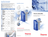
PURELAB Prima 7/15/30
Operator Manual


ELGA PURELAB Prima 7/15/30 Operator Manual
PURELAB Prima 7/15/30 Version 01 09/08 Page i
Copyright Note
The information contained in this document is the property of VWS
(UK) Ltd. and is supplied without liability for errors or omissions.
No part of this document may be reproduced or used except as
authorized by contract or other written permission from VWS (UK) Ltd.
The copyright and all restrictions on reproduction and use apply to all
media in which this information may be placed.
VWS (UK) Ltd. pursue a policy of continual product improvement and
reserve the right to alter without notice the specification, design, price
or conditions of supply of any product or service.
© VWS (UK) Ltd. 2008
All rights reserved
Publication ref: MANU38902
Version 01 – 09/08

PURELAB Prima 7/15/30 Operator Manual ELGA
Page ii PURELAB Prima 7/15/30 Version 01 09/08
TABLE OF CONTENTS
1. INTRODUCTION ..................................................................... 1
1.1 Product Range ............................................................... 1
1.2 Use of this Manual ......................................................... 1
1.3 Customer Support .......................................................... 1
2. HEALTH AND SAFETY NOTES ............................................. 2
2.1 Electricity ........................................................................ 2
2.2 Pressure......................................................................... 2
2.3 Sanitization Chemicals .................................................. 2
2.4 Control of Substances Hazardous to Health (COSHH) . 2
3. PRODUCT AND PROCESS DESCRIPTION .......................... 3
3.1 Product Description ....................................................... 3
3.2 Process Description ....................................................... 4
3.3 Technical Specifications ................................................ 6
4. CONTROLS ........................................................................... 10
5. INSTALLATION INSTRUCTIONS ........................................ 11
5.1 Unpacking the PURELAB Prima ................................ 11
5.2 Positioning the PURELAB Prima ................................ 11
5.3 Connecting up the PURELAB Prima .......................... 13
5.4 Initial Controller Set-Up ................................................ 15
5.5 Initial Start Up .............................................................. 17
6. OPERATION .......................................................................... 18
6.1 Alarm Conditions ......................................................... 18
7. MAINTENANCE .................................................................... 19
7.1 Replacing the LC140 Pre-treatment Cartridge ............ 20
7.2 Cleaning the Inlet Strainer ........................................... 21
7.3 Replacement of LC143 Reverse Osmosis Cartridge(s)21
8. SANITIZATION PROCEDURES ........................................... 22
8.1 CT1 Sanitization Tablet - Safety Information ............... 23
9. TROUBLE SHOOTING ......................................................... 24
10. CONSUMABLES AND ACCESSORIES ............................... 25
11. KEY TO CONTROL PANEL .................................................. 26
11.1 Icons ............................................................................ 26
11.2 Alarm Conditions ......................................................... 26
11.3 Replacement Timers .................................................... 26
11.4 Quality and Standby Alarms ........................................ 27
12. WARRANTY/CONDITIONS OF SALE .................................. 28
13. USEFUL CONTACT DETAILS.............................................. 30

ELGA PURELAB Prima 7/15/30 Operator Manual
PURELAB Prima 7/15/30 Version 01 09/08 Page 1
1. INTRODUCTION
1.1 Product Range
This Operator Manual has been prepared for the PURELAB Prima
product models:
PURELAB Prima 7
PURELAB Prima 7 BP (with boost pump)
PURELAB Prima 15
PURELAB Prima 15 BP (with boost pump)
PURELAB Prima 30
PURELAB Prima 30 BP (with boost pump)
1.2 Use of this Manual
This manual contains full details on installation, commissioning and
operation of the PURELAB Prima unit. If this unit is used contrary to
the instructions in this handbook, then the safety of the user may be
compromised.
1.3 Customer Support
Service support and consumable items are available from your local
supplier or distributor. Refer to customer service contact details
shown at the end of this publication.
PURELAB Prima

PURELAB Prima 7/15/30 Operator Manual ELGA
Page 2 PURELAB Prima 7/15/30 Version 01 09/08
2. HEALTH AND SAFETY NOTES
PURELAB Prima products have been designed to be safe, however,
it is important that personnel working on these units understand any
potential dangers. All safety information detailed in this handbook is
highlighted as WARNING and CAUTION instructions. These are used
as follows:
WARNING! WARNINGS ARE GIVEN WHERE FAILING
TO OBSERVE THE INSTRUCTION COULD
RESULT IN INJURY OR DEATH TO
PERSONS.
CAUTION! Cautions are given where failure to
observe the instruction could result in
damage to the equipment, associated
equipment and processes.
2.1 Electricity
It is essential that the electrical supply to the PURELAB Prima is
isolated before any items are changed or maintenance work
performed.
The ON/OFF switch is located at the left-hand side of the unit. The
mains power lead is located just behind the ON /OFF switch.
WARNING! THIS APPLIANCE MUST BE EARTHED.
2.2 Pressure
The main water supply pressure should be isolated and residual
pressure released prior to removal of any cartridges or carrying out
work on the unit.
Switching off the electrical supply will isolate the source of pressure,
but pressure trapped within the unit should be released.
2.3 Sanitization Chemicals
During the sanitization cycle a CT1 sanitization tablet is used and
relevant safety information is included in this handbook. A safety data
sheet conforming to COSHH regulations is also provided with the
tablets and should be read before the tablet is used.
2.4 Control of Substances Hazardous to Health (COSHH)
Material safety data sheets covering the various replaceable
cartridges are available upon request. Contact your local supplier or
distributor.
Fuse
ON/OFF
switch
Mains
p
ower lead
Mains
p
ower socket
Mains Power Supply

ELGA PURELAB Prima 7/15/30 Operator Manual
PURELAB Prima 7/15/30 Version 01 09/08 Page 3
3. PRODUCT AND PROCESS
DESCRIPTION
3.1 Product Description
The PURELAB Prima water purification unit has been specifically
designed to provide a supply of purified 'primary' grade water for
laboratory, medical and industrial applications.
The PURELAB Prima can be bench or wall mounted with an optional
wall mounting kit. A range of accessories are available to complement
the unit. (See Section 10 – Consumables and Accessories, for detail).
Sanitization port
Powe
r
switch ON/OFF
Mains powe
r
socket
Fuse
Feedwater inlet
connection
Removeable cover
Control panel
Door
PURELAB Prima

PURELAB Prima 7/15/30 Operator Manual ELGA
Page 4 PURELAB Prima 7/15/30 Version 01 09/08
3.2 Process Description
The PURELAB Prima process links two purification technologies,
reverse osmosis, adsorption and also incorporates an optional RO
feed water boost pump.
The unit is designed to operate from a good quality potable water
supply, at 15°C and produces 7, 15 or 30 liters per hour of purified
reverse osmosis grade water which is delivered to a treated water
reservoir.
A graphics screen displays the system status and provides control by
means of three function buttons.
The water is processed and treated by the PURELAB Prima unit as
follows:
• Potable water enters through a strainer and inlet solenoid
valve at either regulated mains water pressure, or is pumped
by means of a feed water pump (optional), and passes
through the pre-treatment cartridge. The pre-treatment
cartridge has been designed to protect the reverse osmosis
cartridges from particulate/colloidal matter and excessive
free chlorine, which may be present in the incoming
feedwater.
• The water then passes the sanitization port and through
one, two or three reverse osmosis cartridges, set up in
series, which split the flow into permeate and concentrate
streams. The permeate water is further purified whilst the
waste concentrate stream is passed to drain.
• The permeate water is passed through a:
• Water quality sensor, which measures the conductivity of
the water.
• Temperature sensor which provides accurate
temperature measurement.
• Finally, the purified water is delivered to a treated water
reservoir.
• To ensure that the quality of the purified outlet water from
the unit is maintained at its highest level, the unit has an in-
built automated auto-rinse cycle. The auto-rinse cycle is
performed every time the process is initiated and consists of
a 1 minute high flow rinse to drain across the reverse
osmosis cartridges.

ELGA PURELAB Prima 7/15/30 Operator Manual
PURELAB Prima 7/15/30 Version 01 09/08 Page 5
Temp
measurement
Water quality
sensor
Outlet Outlet Outlet
Drain Drain Drain
Reverse
Osmosis
LC143
Reverse
Osmosis
LC143
Reverse
Osmosis
LC143
Inlet Inlet Inlet
Feed water
inlet
Sanitization
Port
Strainer
Solenoid
Boost
pump
(optional)
Pre-treatment
LC140
Concentrate
drain
Auto rinse
solenoid
with internal
bypass
Product outlet
(permeate)
Dispense
Tap
Process Flow - PURELAB Prima
Reservoir

PURELAB Prima 7/15/30 Operator Manual ELGA
Page 6 PURELAB Prima 7/15/30 Version 01 09/08
3.3 Technical Specifications
The Technical Specifications for the PURELAB Prima are as follows:
Feedwater
PURELAB Prima 7 PURELAB Prima 15 PURELAB Prima 30
Feedwater
Source Quality Potable mains water
supply
Potable mains water
supply
Potable mains water
supply
Fouling Index-maximum 10 10 10
Total Dissolved Solids-maximum 1400µS/cm 1400µS/cm 1400µS/cm
Free Chlorine-maximum 0.5ppm 0.5ppm 0.5ppm
Chloramine-maximum 0.5ppm 0.5ppm 0.5ppm
Heavy Metals - maximum 0.05ppm 0.05ppm 0.05ppm
Silica - maximum 30ppm 30ppm 30ppm
TEMPERATURE 1 - 35°C 1 - 35°C 1 - 35°C
FLOWRATE (maximum requirement) 145 l/hr 150 l/hr 155 l/hr
Drain requirements (gravity fall with air gap).
Maximum during service
70 l/hr 70 l/hr 80 l/hr
Feedwater Pressure
Maximum - without internal boost pump 6.0 bar (90 psi) 6.0 bar (90 psi) 6.0 bar (90 psi)
Minimum - without internal boost pump 4.0 bar (60 psi) 4.0 bar (60 psi) 6.0 bar (90 psi)
Maximum - with internal boost pump 2.0 bar (30 psi) 2.0 bar (30 psi) 2.0 bar (30 psi)
Minimum - with internal boost pump Flooded Suction Flooded Suction 1.0 bar (15 psi)
Dimensions
Height 460mm (18.1") 460mm (18.1") 460mm (18.1")
Width 410mm (16.2") 410mm (16.2") 410mm (16.2")
Depth 270mm (10.6") 270mm (10.6") 270mm (10.6")
Weight
With internal boost pump 13.5kg (30lb) 14.5kg (32lb) 15.0kg (33lb)
Without internal boost pump 11.5kg (25lb) 12.5kg (28lb) 13.0kg (29lb)
Connections
Inlet-quick connect 8mm (5/16") OD 8mm (5/16") OD 8mm (5/16") OD
Outlet-quick connect 8mm (5/16") OD 8mm (5/16") OD 8mm (5/16") OD
Drain RO-quick connect 8mm (5/16") OD 8mm (5/16") OD 8mm (5/16") OD
Positioning Wall, bench or under
bench mounted.
Wall, bench or under
bench mounted.
Wall, bench or under bench
mounted.
Environment Clean dry indoor.
Temp 5 - 40°C.
Humidity max 80%
non-condensing.
Clean dry indoor.
Temp 5 - 40°C.
Humidity max 80%
non-condensing.
Clean dry indoor.
Temp 5 - 40°C.
Humidity max 80%
non-condensing.

ELGA PURELAB Prima 7/15/30 Operator Manual
PURELAB Prima 7/15/30 Version 01 09/08 Page 7
Electrical Requirements
Mains input 100-240V ac, 50-60Hz all models
System voltage 24V dc
Power consumption with boost pump 52VA
Power consumption without boost pump 28VA
Fuses 2 x T3.15 Amp
Reservoir level connection Jack Plug 3.5mm
Noise level <45 dBA
User Interface
Display Continuous graphical and numerical reservoir level display
Graphical flow schematic on screen with mimic display
Intuitive Icons
Adjustable settings Auto restart after power failure Selectable
Audible alarm Selectable
Water purity Alarm setpoints
Indicators Reverse osmosis permeate water conductivity
Temperature Degrees centigrade
Reservoir % Full
Pre-treatment cartridge Maximum remaining life indicator
Alarms-Audiovisual Purified water purity Outside set point alarm
Reservoir Low level
Reservoir Level control disconnect alarm
Pre-treatment cartridge Change reminder
Outputs RS232 Printer connection
RS232 Remote display connection
Volt free contact-internal
Safety Features
Power fail safe
Boost pump protection from particulates
Low operating voltage 24V
Audio visual alarms
Adjustable alarm settings

PURELAB Prima 7/15/30 Operator Manual ELGA
Page 8 PURELAB Prima 7/15/30 Version 01 09/08
Special Features
Low Noise Levels – minimum intrusion
Flow rate upgradable
Optional internal boost pump for low pressure feed waters
Optional printer kit for record of operating parameters
Optional remote display
Technologies
Purification Methods Adsorption
Reverse Osmosis
Purified Water Specification
PURELAB Prima 7 PURELAB Prima 15 PURELAB Prima 30
Make Up Rate 7.5 l/hr* 15 l/hr* 30 l/hr**
*Daily Output(nominal max) 180 l/24 hour day 360 l/24 hour day 720 l/24 hour day
Output reverse pressure
(max)
0.1 bar (1 psi) 0.1 bar (1 psi) 0.1 bar (1 psi)
Purity:
Inorganic rejection >90%
Inorganic rejection -Typical 95 to 98% rejection
Organics (TOC) typical <100ppb
Particles >99% rejection
* Standard conditions are 4 bar inlet pressure, <0.1 bar back
pressure at 15 degrees centigrade, and a clean pre-treatment
cartridge. Refer to flow tables at other temperatures and
pressures.
** Standard conditions are 6 bar inlet pressure, <0.1 bar back
pressure at 15 degrees centigrade.
As part of our policy of continual improvement we reserve the right to
alter the specifications given in this document.
Specifications are for a system fed with a suitable water supply and
installed, operated and sanitized according to the Operator Manual.

ELGA PURELAB Prima 7/15/30 Operator Manual
PURELAB Prima 7/15/30 Version 01 09/08 Page 9
PURELAB Prima Reverse Osmosis Capacity Charts
PURELAB
Prima 7
Flow (l/hr)
Pressure
(
bar
)
Graph 1 - Nominal Flowrate vs Inlet Pressure for
PURELAB Prima 7
PURELAB
Prima 15
Flow (l/hr)
Pressure (bar)
Graph 2 - Nominal Flowrate vs Inlet Pressure for
PURELAB Prima 15
Graph 3 - Nominal Flowrate vs Inlet Pressure for
PURELAB Prima 30
Flow (l/hr)
Pressure
(
bar
)
PURELAB
Prima 30
Boost Pump
Fitted

PURELAB Prima 7/15/30 Operator Manual ELGA
Page 10 PURELAB Prima 7/15/30 Version 01 09/08
4. CONTROLS
The PURELAB Prima operates with a tactile membrane touch pad
control panel which has a graphics display window and three program
function control buttons.
Details of how to use the controls will be given in the appropriate
sections.
Control Button Function
PROCESS Turns the process ON/OFF.
The PURELAB Prima control panel has a range of control icons as
follows:
Button Icon Description
LEFT
Menu
Scroll
RIGHT
Reset
Mute Alarm
Accept
Printer
Process button
Right hand
control button
Left hand
control button
Control Panel

ELGA PURELAB Prima 7/15/30 Operator Manual
PURELAB Prima 7/15/30 Version 01 09/08 Page 11
5. INSTALLATION INSTRUCTIONS
5.1 Unpacking the PURELAB Prima
The following items should be supplied with your PURELAB Prima:
1. PURELAB Prima unit.
2. Installation kit (LA513 or LA506).
3. Operator manual.
4. Mains lead.
5.2 Positioning the PURELAB Prima
Before commencing with installation and operation of the PURELAB
Prima unit, please read and observe the following points.
Environment
The unit should be installed on a flat, level surface, in a clean,
dry environment. The unit can also be wall mounted against a
vertical wall capable of supporting the weight (for this we
recommend the use of the wall mounting kit Part No LA 610).
CAUTION! If unit is to be wall mounted, ensure it is
mounted on a substantial solid wall
capable of supporting the operating
weight of the system. If mounting the unit
on the wall, use the wall mounting kit and
follow the instructions included in the kit.
Note: Refer to specifications for unit weights.
The unit is designed to operate safely under the following conditions:
• Indoor use.
• Altitude up to 2000m.
• Temperature Range 5 - 40°C.
• Maximum Relative Humidity 80% at 31°C decreasing
linearly to 50% at 40°C, non-condensating.
The unit is in Installation Category II, Pollution Degree 2, as Safety
Standard IEC1010-1.
Rear mounting locations points
Unit Rear Mounting Points

PURELAB Prima 7/15/30 Operator Manual ELGA
Page 12 PURELAB Prima 7/15/30 Version 01 09/08
Electrical
The units can be connected universally to any electrical supply
in the range of 100 - 240V and 50 - 60Hz. The mains lead is
supplied with a molded plug on one end and a molded
connector to the unit on the other. The unit should be
connected to an earth.
Drain
A semi rigid flexible connection to a sink or suitable drain
capable of handling at least 1.5 l/min is required. The drain
point should have a gravity fall below the level of the unit and
any connections direct to drain should have an air-break device
fitted.
Feed Water
The feed water should be of good quality and comply with
specifications provided. This should enter the unit via an 8mm
(5/16") OD semi rigid tube, and should be in the temperature
range 1 to 35°C.
CAUTION! Operating with feed water temperatures
outside the range from 1 to 35°C will cause
damage to the PURELAB Prima unit.
For pressurized feeds, the minimum direct inlet pressure is
4 bar (60 psi) (6 bar (90 psi) for PURELAB Prima 30) and
maximum inlet pressure is 6 bar (90 psi). Higher feedwater
pressures must be reduced using a pressure regulator valve
(Part No. LA 512).
Reservoir feeds to the PURELAB Prima unit should be
positioned at the same height, or above the unit, to provide a
positive flooded inlet pressure.
PURELAB Prima
Level control cable
RESERVOIR
Outlet
Inlet
Drain
A
ll tube connections 8mm (5/16")
PURELAB Prima Unit Installed with Storage Reservoir
Direction of
water flow
Collar
Collar
Mesh filter
Strainer
Feed Water Strainer
Mains power socket
Mains power lead
Fuse
ON/OFF
switch
Electrical Connections

ELGA PURELAB Prima 7/15/30 Operator Manual
PURELAB Prima 7/15/30 Version 01 09/08 Page 13
Outlet to
reservoi
r
Blank
Blank
Drain
Outlet and Drain Connections
5.3 Connecting up the PURELAB Prima
Once the PURELAB Prima unit has been positioned either on a wall
or on a bench, it should be connected as follows:
• Mains water inlet tube
• Drain
• Outlet to reservoir
Step 1 - Fitting Tubes
1. PUSH in collet on connector.
2. PULL out transit plug.
3. CUT a clean square end on a 8mm OD semi rigid
drain tube.
4. PUSH tube into connector.
CAUTION! Do not restrict drain line.
CAUTION! If the water supply is at a pressure greater
than 6 bar (90 psi) fit a pressure regulator
(LA 512).
Connecto
r
Collet
Blanking
transit plug
Pull
p
lu
g
Depress
collet
Clean square
cut end
Tube 8mm OD
Simply push in tube to attach
Tube in secured position
Fitting tubes
Feed Water Inlet Connection

PURELAB Prima 7/15/30 Operator Manual ELGA
Page 14 PURELAB Prima 7/15/30 Version 01 09/08
Step 2 - Connect Electrical Supply
1. PLUG mains lead into the socket on the left hand
side of the PURELAB Prima unit.
2. PLUG mains lead into mains socket.
Step 3 - Connect High/Low Level Switch to Reservoir
1. INSERT jack plugs into the level control socket
located at rear of unit and reservoir.
Mains power socket
Fuse
ON/OFF
switch
Mains power lead
Electrical Connections
Level control
Reservoir Level Connections

ELGA PURELAB Prima 7/15/30 Operator Manual
PURELAB Prima 7/15/30 Version 01 09/08 Page 15
5.4 Initial Controller Set-Up
The PURELAB Prima control panel is fitted with three control buttons.
These are:
1. The PROCESS button, which switches the
purification process ON and OFF.
2. Two software controlled touch pad buttons which
are used to control set-up and process control
functions.
When the PURELAB Prima unit is started for the first time after
installation the following steps should be carried out to set up system
preferences:
Step 1 - Setting Up Menu Options
SWITCH the mains power on to initialize the controller
hardware set-up sequence.
Note: Always allow the initialization process
to complete. This is indicated by the
appearance of the MENU icon on the
control screen.
PRESS the MENU button to go to the next screen to activate
the set up menu sequence.
A series of set-up screens will now be displayed. Various
control icons are used to allow you to step through the set-up
instruction process. These icons include:
• A “scroll” icon indicated by an arrow
• An “accept” button indicated by a tick 9
• A “selection” icon indicated by a
Step 2 - Auto/Manual Restart
This allows the selection of the AUTO/MANUAL restart option.
If auto restart is selected the unit will automatically restart after
a power failure. In manual mode the unit will remain in standby.
Select the option required using the button and accept with
the 9 button.
Step 3 - Audible Alarm Enabled/Disabled
This display provides the option of either enabling the audible
alarm, causing it to sound, or disabling the audible alarm
causing it to remain muted, whilst it flashes the alarm icon.
Select the option required using the button and accept with
the 9 button.
Process button
Touch pad buttons
Menu
Start Up Screens
A
uto Restart
Manual Restart
Auto/Manual Restart
A
udible Alarm Enabled
A
udible Alarm Disabled
Audible Alarm
Enable/Disable

PURELAB Prima 7/15/30 Operator Manual ELGA
Page 16 PURELAB Prima 7/15/30 Version 01 09/08
Step 4 - Purity Alarm Setting
The following water purity alarm choices will be displayed.
Select the alarm setting required using the button and
accept with the 9 button.
Note: To reset any of the setup parameters,
restart from the set up MENU and
follow instructions from Step 1.
Setting Up Display and Replacement Timers
Turn the unit off at the power inlet module. To enter the
replacement timer set up, press the left hand touch pad button
and at the same time turn the power on.
A graphic of the pre-treatment cartridge and clock graphics are
displayed with hourly timer status.
CAUTION! Before re-setting any of the cartridge
timers, ensure that the appropriate new
cartridges have been installed and
securely located correctly in the PURELAB
Prima.
Step 1 - Pre-treatment Cartridge Replacement Timer
Setting this screen will cause the pre-treatment cartridge timer
to reset to the preset value of 4380 hours (6 months).
Press 9 to jump to the next consumable or to initiate reset.
Press 9 to reset timer or press to abort reset.
Press 9 to jump to the next consumable.
Step 2 - Accessing the Process On Display Screens
The normal process screen will display newly installed SETUP
preferences showing the following process information:
• Output water purity
• Water temperature
• Process mimic
• Reservoir level
• Scroll and Print icons
You can scroll through the following display screens:
• Pre-treatment cartridge replacement (hours remaining)
Step 3 - Report Printing (Only if connected to LA 618)
To print a report press the icon.
Pre-treatment Cartridge Timer
Process On
Autorinse
Purity Alarm Setting
100 µS/cm
50 µS/cm
20 µS/cm
/