7
Connection (continued)
Contacts on Power/Battery Module
WARNING! High Voltage!
Risk of electrical shock!
Due to the presence of high voltage internal
batteries, even without AC present, these
contacts are live!
Do not let these contacts touch any surface!
Contacts on Detachable PDU
WARNING! High voltage!
Risk of electrical shock!
If AC is present and Bypass Switch is set to
"Bypass", these contacts are live!
Do not let these contacts touch any surface!
4
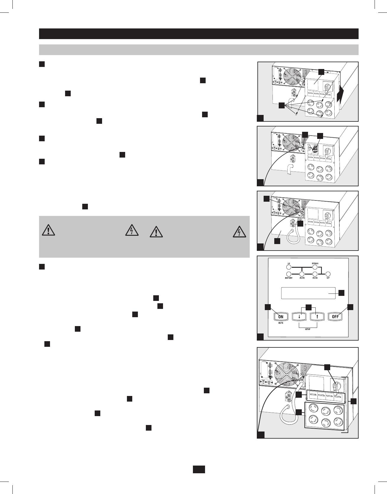
Turn UPS ON
Note: UPS system will function properly upon initial startup; however, maximum runtime for the
unit’s battery will only be accessible after it has been charged for 24 hours.
1. Turn on the breaker for the UPS system’s utility power source. This will energize the UPS
power module and the control panel’s LCD screen
H
will display “BYPASS MODE”.
2. Make sure the PDU module’s manual bypass switch
L
is in the “NORMAL” position.
3. Turn on the PDU output circuit breakers
M
.
4. Configure the UPS system in SETUP MODE. Enter SETUP MODE by holding down both
scroll buttons
J
at the same time.
5. Scroll through the setup options (using the scroll buttons
J
) and press the “SELECT” button
I
to select the appropriate settings:
Input & Output Voltage: Select 200, 208, 220, 230, or 240V AC.
Output Frequency: The UPS system will auto-select 50 or 60 Hz to match the input.
Economy Mode: The UPS system can provide on-line operation with zero transfer
time. It can also operate in a more energy-efficient, line-interactive mode. Select
“ECONOMY ON” for line-interactive mode. Select “ECONOMY OFF” for on-line
mode.
6. After configuring the options, exit SETUP MODE with the scroll buttons
J
.
7. Press the control panel’s “ON” button
I
until the UPS system beeps, then release the button.
8. The UPS system will perform a brief self-test and show the results on the control panel
LEDs and LCD screen
H
. See “Startup Self-Test” in the “Operation” section for the display
sequence.
9. After the self-test is complete, the LCD screen
H
should display “ONLINE MODE” or
“ECONOMY MODE”, depending on which option was selected. The UPS system is now
turned on.
1
Attach the PDU to the Power Module and Battery Module.
Align and connect the PDU’s power module input terminals with the terminals on the back of
the Power Module. Secure the PDU to the Power Module with four screws
A
. Before proceed-
ing further, ensure that the Bypass Switch is set to NORMAL. Remove the utility input terminal
block cover
B
.
2
Hardwire the PDU to a Utility Power Source.
Pass a user-supplied cable through the knockout on the left side of the PDU
C
and connect it to
the PDU’s input terminals
D
. Replace the terminal block cover. Connect the other end of the
cable to a utility power source.
3
Connect the battery module to the power module.
Consult the owner’s manual that came with your battery module. Fully insert the connector on
the end of the battery module’s cable
E
into the connector on the rear panel of the power module
F
. Small sparks may occur; this is normal. NOTE: the power module does not contain internal
batteries and will not start until a battery module is connected. The battery modules are fully
charged prior to shipping. However, before expecting full backup capability (particularly if the
battery module has been stored for an extended period) after the UPS system is connected to a
utility power source, allow the battery module to recharge for 12 hours. Once the UPS system is
in use, it will charge the batteries and maintain the charge level automatically. If needed, connect
additional battery modules in a daisy-chain with each module’s cable inserted into the previous
module’s connector
G
.
Connecting Modules to Each Other and to Utility Power and Equipment
A
B
D
C
F
G
E
H
KI
J
2
3
4a
1
N
M
L
O
4b
201102160 93-2897.indb 7 3/30/2011 9:30:44 AM