Page is loading ...

start here commencez ici
empezar aquí
Assembly Instructions
Item No:
FR41905
Les Instructions D’assemblage
Numéro d’article:
FR41905
Instrucciones De Montaje
Número del artículo:
FR41905
English Spanish French
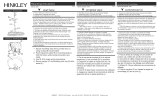
1. Find a clear area in which you can work. r. 1. T r.
stem
wire
wire
wire
stem
Drawing 1 – Stem Assembly
Drawing 2 – Shade Assembly
r
r
r.
r
r
P
r
L
r
L
H I N K L E Y 3 3 0 0 0 Pin O a k P a r kwa y, A von L ak e, OH 44 0 1 2 8 00 .4 4 6 . 55 39 / 44 0 . 6 5 3 . 55 00 hinkley.com
9
8
1
2
5
7
4
3
6
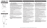
1. Connect quick connectors (11) together
2. Secure top arms (3) to top ring (1) using screws (2)
3. Connect quick connectors (4) together
4. Use screws (5) to secure bottom arms (6) to top ring (1)
5. Next use screws (7) to secure bottom arms (6) to bottom ring
(10)
6. Lamp fixture with appropriate bulbs (8)
7. Secure glass shade (9) to socket
8. Fixture can now be powered on
10
1. Conecte los conectores rápidos (11) juntos
2. Fije los brazos superiores (3) al anillo superior (1) con
tornillos (2)
3. Conecte los conectores rápidos (4) juntos
4. Use tornillos (5) para asegurar los brazos inferiores (6) al
anillo superior (1)
5. Luego use tornillos (7) para asegurar los brazos inferiores (6)
al anillo inferior (10)
6. Luminaria con bombillas adecuadas (8)
7. Asegure la pantalla de vidrio (9) al zócalo
8. Ahora se puede encender el dispositivo
1. Connectez les connecteurs rapides (11) ensemble
2. Fixez les bras supérieurs (3) à l'anneau supérieur (1) à l'aide des
vis (2)
3. Connectez les connecteurs rapides (4) ensemble
4. Utilisez les vis (5) pour fixer les bras inférieurs (6) à l'anneau
supérieur (1)
5. Utilisez ensuite les vis (7) pour fixer les bras inférieurs (6) à
l'anneau inférieur (10)
6. Luminaire avec ampoules appropriées (8)
7. Fixez l'abat-jour en verre (9) à la douille
8. Le luminaire peut maintenant être allumé
11

start here commencez ici empezar aquí
Mounting Instructions IS19-SCLL Instructions de montage IS19-SCLL Instrucciones de montaje IS19-SCLL
English Spanish French
SAFETY WARNING: READ WIRING AND GROUNDING INSTRUC-
TIONS (I.S. 18) AND ANY ADDITIONAL DIRECTIONS. TURN
POWER SUPPLY OFF DURING INSTALLATION. IF NEW WIRING IS
REQUIRED, CONSULT A QUALIFIED ELECTRICIAN OR LOCAL
AUTHORITIES FOR CODE REQUIREMENTS.
ADVERTENCIA DE SEGURIDAD: CABLEADO DE LEER Y
INSTRUCCIONES DE CONEXIÓN A TIERRA (SI 18), E
INSTRUCCIONES ADICIONALES. VUELTA DE ALIMENTACIÓN
DURANTE LA INSTALACIÓN. SI SE REQUIERE UN NUEVO
CABLEADO, CONSULTE A UN ELECTRICISTA O AUTORI-
DADES LOCALES PARA REQUISITOS DEL CÓDIGO.
AVERTISSEMENT DE SÉCURITÉ: CÂBLAGE LIRE ET MISE A LA
TERRE (IS 18) ET TOUTE AUTRE INSTRUCTION. COUPER
L'ALIMENTATION PENDANT L'INSTALLATION. SI DE
NOUVELLES CÂBLAGE NE EST NÉCESSAIRE, CONSULTER UN
ÉLECTRICIEN QUALIFIÉ OU LES AUTORITÉS LOCALES LES
EXIGENCES DES CODES.
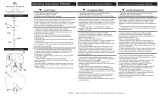
1. To begin installation, first attach mounting strap (A) to junction box
using two 8-32 screws (B) NOT PROVIDED. Make sure the head of the
ground screw is facing down - see DRAWING 1.
2. Next take threaded tube (C) and thread one hex nut (D) onto end. Now
thread end of tube (C) into hanging loop (E) approximately 1/2”. Then
tighten hex nut (D) against back of hanging loop to lock thread tube in
place.
3. Now thread second hex nut (D) onto threaded tube (C). Now thread
tube (C) into center of mounting strap (A) approximately 1/2”.
4. Next it is necessary to adjust the position of hanging loop (E). This is
accomplished by slipping the hanging loop (E) through the center hole in
the ceiling canopy (F). Now thread hanging loop up or down until the top
threaded portion of the loop is approximately 1/4” inside the canopy - see
DETAIL 1. NOTE: A third hex nut (D) is supplied and can be threaded
onto center tube (C) above the mounting strap (A) after adjustments are
made to loop height.
5. Now threaded medallion or screw collar ring [depending on hardware
supplied] (H) and slide onto the fixture wire and over the stems that were
attached to the fixture body earlier, followed by
the canopy (F) -see DETAIL 2.
6. Now lift fixture body and stems up to hanging loop (E). Using the single
chain link supplied, hook the last loop on the fixture stem to the hanging
loop (E), and close chain link.
7. Slip fixture wire through center hole of hanging loop (E) and through
threaded tube (C) until it exits above the mounting strap (A).
8. Make all wiring connection following wiring instructions (IS18) provided.
9. After wire connections are completed slide canopy (F) along stems and
up to ceiling followed by medallion or screw collar (H). While holding
canopy against ceiling, thread (H) onto hanging loop (E), to secure
canopy to in place.
10. Glass can now be installed. See Assemlby instrutcions.
B
C
D
E
F
A
H
J
L
DRAWING 1 - MOUNTING
DETAIL 2
F
STEMS
H
THREADED PORTION
1/4” INSIDE CANOPY
ADJUST LOOP
UP OR DOWN
DETAIL 1
D
stem from
1. Para comenzar la instalación, primero conecte la correa de
montaje (A) a la caja de conexiones con dos tornillos (B 8-32) no
previstos. Asegúrese de que la cabeza del tornillo de tierra esté
hacia abajo - vea el dibujo 1.
2. A continuación, tomar el tubo roscado (C) y el hilo una tuerca
hexagonal (D) en el extremo. Ahora la rosca del extremo del tubo
(C) en el orificio para colgar (E) aproximadamente 1/2 ". A
continuación, apriete la tuerca hexagonal (D) contra la parte
posterior del orificio para colgar para bloquear el tubo de rosca en
su lugar.
3. Ahora segundo hilo tuerca hexagonal (D) sobre el tubo roscado
(C). Ahora enrosque el tubo (C) en el centro de la barra de montaje
(A) aproximadamente 1/2 ".
4. A continuación, es necesario ajustar la posición del bucle de
colgar (E). Esto se logra deslizando el orificio para colgar (E) a
través del orificio central en la cubierta del techo (F). Ahora el hilo
colgando de bucle hacia arriba o hacia abajo hasta que la parte
roscada superior del bucle es aproximadamente 1/4 "dentro del
dosel - ver detalle 1. Se suministra una tercera tuerca hexagonal
(D) y se puede enroscar en el tubo central (C) por encima de la
correa de montaje (A) después de ajustar la altura del bucle.
5. medallón Ahora roscado (H) y se deslizan sobre el alambre de
fijación y sobre los tallos que se une al cuerpo del útil antes,
seguido de
el dosel (F) -ver detalle 2.
6. Ahora la elevación del cuerpo del accesorio y tallos hasta
gancho para colgar (E). Usando el enlace de cadena única
suministrado, enganchar el último bucle en el vástago de fijación al
bucle colgante (E), y cerca de la conexión de cadena.
7. Ahora deslizar el cable accesorio través del orificio central de
gancho para colgar (E) y por el tubo roscado (C) hasta que sale
por encima de la barra de montaje (A).
8. Haga todas las conexiones de cableado siguiendo las instruc-
ciones de cableado (IS18), siempre.
9. dosel diapositiva Después de conexiones de los cables se han
completado (F) a lo largo de los tallos y hasta el techo seguido por
medallón (H). Mientras mantiene dosel contra el techo, medallón
rosca (H) en colgar bucle (E), para asegurar dosel en su lugar.
10. Cristal se puede instalar ahora. Ver instrucciones de montaje.
1. Pour commencer l'installation, fixez d'abord la sangle de fixation
(A) à la boîte de jonction en utilisant deux vis 8-32 (B) NON
PREVUES. Assurez-vous que la tête de la vis de terre est orienté
vers le bas - voir schéma 1.
2. Prenez ensuite le tube fileté (C) et visser un écrou hexagonal (D)
sur l'extrémité. Maintenant, le fil extrémité du tube (C) dans la boucle
de suspension (E) d'environ 1/2 ". Puis serrer l'écrou hexagonal (D)
contre le retour de la boucle d'accrochage pour verrouiller le tube de
fil en place.
3. Maintenant, deuxième fil écrou hexagonal (D) sur le tube fileté
(C). Maintenant fil tube (C) dans le centre de la sangle de fixation (A)
d'environ 1/2 ".
4. Ensuite, il est nécessaire d'ajuster la position de boucle de
suspension (E). Ceci est réalisé en faisant glisser la boucle de
suspension (E) à travers le trou central dans la voûte du plafond (F).
Maintenant, enfiler la boucle de raccrocher ou vers le bas jusqu'à ce
que la partie filetée de sommet de la boucle est d'environ 1/4 "à
l'intérieur de la canopée - voir DETAIL 1. REMARQUE: Un troisième
écrou hexagonal (D) est fourni et peut être enfilé sur le tube central
(C) au - dessus de la sangle de montage (A) après avoir ajusté la
hauteur de la boucle.
5. Maintenant médaillon fileté (H) et glisser sur le fil de fixation et sur
les tiges qui ont été fixé au corps de fixation précédemment, suivie
par
la canopée (F) -voir DETAIL 2.
6. Maintenant, soulevez le corps du luminaire et tiges jusqu'à boucle
de suspension (E). En utilisant le lien à chaîne unique fourni,
brancher la dernière boucle sur le montage tige à la boucle de
suspension (E), et à proximité de maillon de chaîne.
7. Maintenant, faites glisser le fil de fixation dans le trou central de la
boucle de suspension (E) et par le tube fileté (C) jusqu'à ce qu'il
quitte au-dessus de la sangle de fixation (A).
8. Faire toutes les connexions de câblage suivant les instructions de
câblage (de IS18) fournies.
9. Une fois que les connexions de fils sont terminées dais à glissière
(F) le long des tiges et jusqu'au plafond suivi par médaillon (H). Tout
en maintenant couvert contre le plafond, fil médaillon (H) sur boucle
de suspension (E), pour assurer la canopée à l'endroit.
10. Le verre peut maintenant être installé. Voir les instructions de
montage.
(or)
D
H I N K L E Y 3 3 0 0 0 Pin O a k P a r kwa y, A von L ak e, OH 44 0 1 2 8 00 .4 4 6 . 55 39 / 44 0 . 6 5 3 . 55 00 hinkley.com

I.S. 18 wiring grounding instructions
SAFE TY WARNI NG: READ WIRIN G AND GR OUNDING
INSTRUCTIO NS (IS 18) AND ANY ADDITIONAL DIRECTIONS.
TURN POWER SUPPLY OFF DURING INSTALLATION. IF NEW
WIRING IS REQUIRED, CONSU LT A QUALIFIED ELECTRICIAN OR
LOCAL AUTHORITIES FOR CODE REQUIREMENTS
wiring instructions
Indoor Fixtures
1. Connec t po siti ve supp ly wire (A ) (typically black or the smoo th,
unma rked side of the two-conduc tor cord) to positive fi xture lead (B )
wit h appropriately sized t wist on connec tor - see Dra w ings 1 o r 2 .
2. Connec t nega tive supp ly wi re (C) (typica lly white or the ribbed , marked
side of the two-conduc tor cord) to nega tive fi xture lead (D).
3. Ple ase refe r to the grounding instructions below to complet e all
electrical connec tion s
Outdoor Fixtures
1. Connec t po siti ve supp ly wire (A ) (typically black or the smoo th
unma rked side of the two-conduc tor cord) to positive fi xture lead (B)
wit h appropriately sized twist on connec tor --- see Draw ings 2 or 3.
2. Connec t nega tive supp ly wi re (C) (typica lly white or the ribbed , marked
side of the two-conduc tor cord) to nega tive fi xture lead (D).
3. Cove r open end of connec tors with silicone sealant to fo rm a
watert ight seal.
If installing a wall moun t fi xture, use cau lk to seal gaps between the
fi xture mo unting p late (backpla te) and the wall. This will help prevent
wa ter fr om entering the out let box . If the wal l surf ace is lap siding, use
cau lk and a fi xture moun ting plat form specially.
4. Ple ase refe r to the grounding instructions below to complet e all
electrical connec tion s.
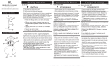
grounding instructions
Flush Mount Fixtur es
For positive ground ing in a 3-wire elect ri cal system, f asten the fixture
ground wir e (E) (typ ically coppe r or green plasti c coated) to the fi xture
moun ti ng strap (M ) w ith the ground screw (S) - see Dr aw in g 1 .
Note: On straps for screw supported fixtures, first install the two mounting
screws in strap. Any remaining tapped hole may be used for the ground screw.
Chain Hung Fixtur es
Loop fi xture ground wir e (E) (typically coppe r or green plastic coa ted)
unde r the head of the ground screw (S ) on fi xture mo unti ng strap ( M )
and connec t to the l oo se end of the fi xture ground wire directly to the
ground wir e of the building system wit h appropriately sized twist-on
connec tors - see Dr aw in g 2 .
Post-Mou nt Fixtur es
Connec t fi xture ground w ire ( E ) (typically copper or green plastic coa ted)
to power supp ly ground wit h app ropri ately sized twi st-on connec tor
inside post. Cove r open end of connec tor with silicone sealant to form a
watert ight seal - see Drawing 3.
I.S. 18 câblage échouage instructions
AVERTIS SEMEN T DE SECURITE: LIRE CABL AGE ET INSTRUCTI ONS DE
MISE (IS 18), ET TOUTE AUTRE INSTRUCTION. COUPER L’ALIMENT ATION
ELECTRI QUE PENDANT L’ONSTALLATI ON. SI DE NOUVELLES CABLAGE
N’EST NECESS AIRE, CONSULTEZ UN E LECTRICIE N QUALIFIE OU
AUTORITE S LOCALE S POUR EXI GENCES DU CODE.
instructions de câblage
Luminaires Itérieurs
1. Branche r le fi l d’al imentation po sitive (A ) (généra lemen t noi r ou, côté lisse
bana li sée de la corde á deux condu cteu rs) á plob de fi xati on posi tive (B) avec
la torsion de taille app rop riée sur le connec teur --- V oir Schéma 1 ou 2.
2. Connec ter le fi l d’a limen tation néga ti ve (C) (génér alement blanc ou l’, côté
ma rqué nervurée du fi l á deux conducteurs) au conduc teur négat if de
l’a ppareil (D).
3. S’i l vous plaît se réfé rer á la mise á la terre instructions ci-des sous pour
terminer toutes les connex ions élect riques .
Lu minaires Ex t é rieurs
1. Branche r le fi l d’al imentation po sitive (A ) (généra lemen t noi r ou le côté lisse
bana li sée de la corde á deux condu cteu rs) á plomb de fi xat ion positive (B)
avec l a torsion approrpriately taille du connecteur --- Voir Schéma 2 ou 3.
2. Connec ter le fi l d’a limen tation néga ti ve (C) (génér alement blanc ou l’, côté
ma rqué nervurée du fi l á deux conduc teurs) au conduc teur négat if de
l’ apparei ld (D ).
3. Couv rir extr émi té ouve rte de conn ecteur s acex du silicone pou r f ormer un
joint étenche á l’eau.
Si l’instal lation d’un l umina ire de montage mural, utiliser calf eut rage pou r
sceller l’espace entre la plaque de mon tage de fi xa tion (plaque ar ri ére) et la
paroi. Cela aidera á empêche r l’eau de péné trer dan s le boc sortie. Si la
surface du mur est bardage á clin, utiliser caldeutrage et une plate-forme de
mon tage d’appa reils spécialement .
4. S’i l vous plait se re ferrer auc instruction s ci-des sou s pou r termine r la ter re
toutes les connexion s électrques.
instructions de mise
Montage Encastré Fixtur es
Pou r l a terre positive dan s un systéme électr ique á 3 fil s, fi xez le fil de terre du
luminaire (E) (géné ralement en cuivre ou ver t recouver t de plastique) á la sang le
de fi xat ion de fi xa tion (M) avec la vis de te rre (S) --- V oir Schéma 1.
Remarque: Sur les sangles pour les appareils pris en charge á vis, installez d’abord les
deux vis de fixation á sangle. Tout trou taraudé restante peut être utilisée pour la vis de
terre.
Chaîne Accroc hé Luminaires
Bouc le fi l du lumina ir e au sol (E) (général ement en cuivre ou vert recouve rt de
plasti que) sous la tê te de la vis de terre (S) sur la sangle de fi xati on de fi xation
(M ) et se connec ter á l’ext rémi tr é libre du fi l de terre du l umina ire directemen t
sur le fi l de terre du systéme de construction avec une ta ille app ropriée
connec teurs á visser --- V oir Schéma 2.
Luminaires Ap rés Mo ntage
Branche r le fi l de te rre du lumina ire (E ) (génér aleme nt en cuivr e ou vert
recouve rt de plastique) á la mas se de l’alimentation avec une taille app ropriée
torsion sur le connec teur á l’intérieur de la poste. Couvr ir extrémité ouver te du
connec teur avec du mast ic silicone pour f ormer un joint étache á l ’eau --- Voir
Schéma 3.
I.S. 18 tierra cableado instrucciones
ADVER TENCI A DE SEGURIDAD : LEA LAS INSTRUCCIONES DE CABLEADO
Y LA TIERR A (IS 18), E INSTRUCCIONES ADICI ONALES . APAUGE LA
ALIMENTACIÓN DE CORR IENTE DURANTE LA INSTALACIÓN. SI SE
REQU IERE NUEVO CABLEADO, CONSUL TE CON UN ELECTRICIST A O
AUTHORID ADES LOCAL ES PARA REQUISITO S DEL CÓDIGO
Instrucciones de cableado
Acesorios C ubierta
1. Conec te el cable de alimentación positive (A ) (no rmalmen te negro o la cara
lisa, sin marcas del cable de dos conduc tores) de plomo acce sorio positivo (B)
con un gir o de tamaño adecuado en el conec tor --- V éa se la Figura 1 y 2.
2. Conec te el cable de alimentación nega ti va (C) (po r lo gene ral de color
blanco o el lado marcado estriado del cable de dos conduc tores) de plomo
acces orio negativo (D).
3. Por f avor, con sulte las instruccione s de pues ta a tierra-a con tinuac ión para
comp letar todas las conex iones eléctricas.
Accesorios E x te rior
1. Conec te el cable de alimentación positiva (A ) (no rmalmen te negro el lado no
ma rcado suave del cab le de dos condu ctores) de plomo acce sorio positi vo (B)
con un gir o de tamaño app rorpriate ly conec tor --- V éa se la Figura 2 y 3.
2. Conec te el cable de alimentación nega ti ve (C) (po r lo gene ral de color
blanco o el lado marcado estriado del cable de dos conduc tores) de plomo
acces orio negativo (D).
3. Cub ra el ext reme ab ierto de conecto res con sellador de silicona poa ra formar
un sello hermético.
Si va a i nstalar un sopo rt e de fi jación mural, use mas illa para sella los
espacios entre la placa de monta je del apa rato (placa) y l a pa red. Esto
ayuda rá a evitar que el agua ent re en la boc sal ida. Si la supe rfi cie de la
pared es de revestim iento solapado , utilice mas illa y una plataforma de
montaje acce sorio especial .
4. Por fa vor, consulte las Instrucciones de puesta a tierra -a cont inuac ión pa ra
comp letar todas las conex iones eléctricas.
instrucciones puesta a tierra
Montaje Embutido Accesorio s
Par a conect ar a tierr a en un sistem a elé ctrico de 3 hilos, fi je el cable de tie rra
del arte facto (E ) (generalme nte de cobre o verd e recubierto de plástico) a la
brida de montaje accesorio (M) con el tornillo de tierr a (S) --- Véase la Figura 1.
No ta : En las correas de accesor ios compati bles tornillos, pr imero instale lo s dos
tornillos de mon taje de la corr ea. Cua lquier agu jero roscado restante puede ser
utilizado para el to rnillo de tierra.
Cadena Hung Accesorios
Loop alamb re de tierra (E) (gene ralmen te de cobre o verde recub iert o de
plát ico) deba jo de la cab eza del t ornill o de tierra (S) en la bri da de montaje
acces orio (M) y conec tar con el ext remo suelt o del cable de tierra luminar ia
directame nte al cable de tierra del sistema de constr ucción con un tamaño
adecu ado twist-conectores --- V éase la Figura 2.
Accesorios Post erior Mont e
Conec te el cable de tierr a del arte facto (E ) (gener almente de cobre o verde
rec ubierto de plástico) a tierra de la fuente de aliment acón con conec tor de
tamanño adecua do en el interi or puesto enlaces en f orma. Cub ra el extremo
abierto del conecto r con sellador de silicona para formar un sello he rmético ---
Véase la Figura 3.
Drawin
g
1 – Flus h M ount
Drawing 2 – Chain Hung
Drawin
g
3 – Post-M ount
S
M
M
S
H I N K L E Y 3 3 0 0 0 Pin O a k P a rk wa y, A von Lak e, O H 440 1 2 8 00 .4 4 6 . 55 39 / 4 4 0.6 5 3 . 55 0 0 hinkley.com
/