Page is loading ...

start here commencez ici empezar aquí
Assembly Instructions
Item No: 83855
Les Instructions D’assemblage
Numéro d’article: 83855
Instrucciones De Montaje
Número del artículo: 83855
English Spanish French
1. Find a clear area in which you can work. r. 1. T r.
SAFETY WARNING: READ WIRING AND GROUNDING INSTRUC-
TIONS (I.S. 18) AND ANY ADDITIONAL DIRECTIONS. TURN
POWER SUPPLY OFF DURING INSTALLATION. IF NEW WIRING IS
REQUIRED, CONSULT A QUALIFIED ELECTRICIAN OR LOCAL
AUTHORITIES FOR CODE REQUIREMENTS.
Make electrical connections from supply wire to fixture lead wires.
Refer to instruction sheet (I.S. 18) and follow all instructions to make
all necessary wiring connections. Then refer back to this sheet to
complete installation of this fixture.
ADVERTENCIA DE SEGURIDAD: CABLEADO DE LEER Y
INSTRUCCIONES DE CONEXIÓN A TIERRA (SI 18), E
INSTRUCCIONES ADICIONALES. VUELTA DE ALIMENTACIÓN
DURANTE LA INSTALACIÓN. SI SE REQUIERE UN NUEVO
CABLEADO, CONSULTE A UN ELECTRICISTA O AUTORI-
DADES LOCALES PARA REQUISITOS DEL CÓDIGO.
AVERTISSEMENT DE SÉCURITÉ: CÂBLAGE LIRE ET MISE A LA
TERRE (IS 18) ET TOUTE AUTRE INSTRUCTION. COUPER
L'ALIMENTATION PENDANT L'INSTALLATION. SI DE
NOUVELLES CÂBLAGE NE EST NÉCESSAIRE, CONSULTER UN
ÉLECTRICIEN QUALIFIÉ OU LES AUTORITÉS LOCALES LES
EXIGENCES DES CODES.
-
720
TO VIEW
720
DR WING 1 - LY
1.
B
A
1. 1.
LARK 33000 PIN OAK PARKWAY, AVON LAKE, OH 44012 LarkLiving.com
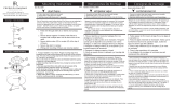
1. To begin assembly take main body (1) and rotate the arms (A) until
they are equally spaced 72 degrees apart and aligned with the opposite
arm. Next rotate the bottom arms until they align with the top arm
location - see Drawing 1.
2. Next, determine the height the fixture has to be installed. This will
determine the number of stems (2) that will be required. If installing over
a table 32 to 35 inches above the top surface is recommended.
3. Now take the stems (2) and slip the wires from the fixture through the
center of the first stem, slip stem along wire and thread it onto threaded
tube (B) found on the top of the main body (1).
4. Slip on the next stem and thread it onto the first stem, until all stems
are installed.
5. Now slide screw collar loop (3) over the stems. This may have to be
removed from the large diameter threaded portion of swivel
assembly (5).
6. Next slide canopy (4) over the stems (2)
7. Now thread wire through center of swivel assembly (5) and thread
swivel assembly into top of the last stem.
8. Now follow mounting instruction sheet (I.S.19-81) and wiring
instructions (IS-18) to complete installation..
3
1
2
2
4
51. Para comenzar el ensamblaje, tome el cuerpo principal (1) y
gire los brazos (A) hasta que estén igualmente separados 72
grados y alineados con el brazo opuesto. A continuación, gire los
brazos inferiores hasta que se alineen con la ubicación del brazo
superior; consulte el Dibujo 1.
2. A continuación, determine la altura a la que debe instalarse la
luminaria. Esto determinará el número de tallos (2) que se
requerirán. Si se instala sobre una mesa de 32 a 35 pulgadas
por encima de la superficie superior, se recomienda.
3. Ahora tome los vástagos (2) y deslice los cables del accesorio
a través del centro del primer vástago, deslice el vástago a lo
largo del cable y enrósquelo en el tubo roscado (B) que se
encuentra en la parte superior del cuerpo principal (1).
4. Deslice el siguiente vástago y enrósquelo en el primer
vástago, hasta que todos los vástagos estén instalados.
5. Ahora deslice el lazo del cuello del tornillo (3) sobre los tallos.
Es posible que sea necesario quitarlo de la parte roscada de
gran diámetro de la pieza giratoria.
montaje (5).
6. A continuación, deslice la cubierta (4) sobre los tallos (2)
7. Ahora pase el cable por el centro del conjunto giratorio (5) y
enrosque el conjunto giratorio en la parte superior del último
vástago.
8. Ahora siga la hoja de instrucciones de montaje (I.S.19-81) y el
cableado instrucciones (IS-18) para completar la instalación.
1. Pour commencer l'assemblage, prenez le corps principal (1) et
faites pivoter les bras (A) jusqu'à ce qu'ils soient équidistants de 72
degrés et alignés avec le bras opposé. Faites ensuite pivoter les
bras inférieurs jusqu'à ce qu'ils soient alignés avec l'emplacement
du bras supérieur - voir Dessin 1.
2. Ensuite, déterminez la hauteur à laquelle le luminaire doit être
installé. Cela déterminera le nombre de tiges (2) qui seront
nécessaires. Si l'installation sur une table de 32 à 35 pouces
au-dessus de la surface supérieure est recommandée.
3. Maintenant, prenez les tiges (2) et glissez les fils du luminaire à
travers le centre de la première tige, glissez la tige le long du fil et
enfilez-le sur le tube fileté (B) situé sur le dessus du corps principal
(1).
4. Enfilez la tige suivante et enfilez-la sur la première tige, jusqu'à
ce que toutes les tiges soient installées.
5. Faites maintenant glisser la boucle du collier à vis (3) sur les
tiges. Cela peut devoir être retiré de la partie filetée de grand
diamètre du pivot
montage (5).
6. Faites ensuite glisser la verrière (4) sur les tiges (2)
7. Enfilez maintenant le fil à travers le centre de l'assemblage
pivotant (5) et vissez l'assemblage pivotant dans le haut de la
dernière tige.
8. Suivez maintenant la fiche d'instructions de montage (I.S.19-81)
et le câblage
instructions (IS-18) pour terminer l'installation.

start here commencez ici empezar aquí
Mounting Instructions (IS19-81)
Item No:
Instructions De Montage (IS19-81)
Numéro d’article:
Instrucciones De Montaje (IS19-81)
Número del artículo:
English Spanish French
1. Find a clear area in which you can work.
SAFETY WARNING: READ WIRING AND GROUNDING INSTRUC-
TIONS (I.S. 18) AND ANY ADDITIONAL DIRECTIONS. TURN POWER
SUPPLY OFF DURING INSTALLATION. IF NEW WIRING IS
REQUIRED, CONSULT A QUALIFIED ELECTRICIAN OR LOCAL
AUTHORITIES FOR CODE REQUIREMENTS.
(I.S. 18)
ADVERTENCIA DE SEGURIDAD: CABLEADO DE LEER Y
INSTRUCCIONES DE CONEXIÓN A TIERRA (SI 18), E
INSTRUCCIONES ADICIONALES. VUELTA DE ALIMENTACIÓN
DURANTE LA INSTALACIÓN. SI SE REQUIERE UN NUEVO
CABLEADO, CONSULTE A UN ELECTRICISTA O AUTORI-
DADES LOCALES PARA REQUISITOS DEL CÓDIGO.
AVERTISSEMENT DE SÉCURITÉ: CÂBLAGE LIRE ET MISE A LA
TERRE (IS 18) ET TOUTE AUTRE INSTRUCTION. COUPER
L'ALIMENTATION PENDANT L'INSTALLATION. SI DE
NOUVELLES CÂBLAGE NE EST NÉCESSAIRE, CONSULTER UN
ÉLECTRICIEN QUALIFIÉ OU LES AUTORITÉS LOCALES LES
EXIGENCES DES CODES.
-
Drawing 1 - Fixture Mounting
-
LARK 33000 PIN OAK PARKWAY, AVON LAKE, OH 44012 LarkLiving.com
C
L
S
J
A
B
3.
T
a
1
1

I.S. 18 wiring grounding instructions
SAFETY WARNING: READ WIRING AND GROUNDING
INSTRUCTIONS (IS 18) AND ANY ADDITIONAL DIRECTIONS.
TURN POWER SUPPLY OFF DURING IN STALLATION. IF NEW
WIRING IS REQUIRED, CONSU LT A QUALIF IED ELECTRICIAN OR
LOCAL AUTHORITIES FOR CODE REQUIREMENTS
wiring instructions
Indoor Fixtures
1. Connec t po siti ve supp ly w ire (A ) (typic ally bl ack or the smoo th,
unma rked side of the t wo-conduc tor cord) to posi tive fixture lead (B )
wit h ap prop riately si zed twi st on connec tor - see Drawings 1 or 2 .
2. Connec t nega tive supp ly wi re ( C) (t ypica lly w hite or the ri bbed , marked
side of t he tw o-conduc tor cord) to ne gative fixt ure le ad ( D).
3. Ple ase re fe r to the g rounding i nstructions below to comp let e all
electrical connec tion s
Outdoor Fixtures
1. Connec t po siti ve supp ly w ire ( A ) (t ypically bl ack or the smoo th
unma rked side of the t wo-conduc tor cord) to posi tive fixture lead (B )
wit h ap prop riately si zed twi st on connec tor --- see D raw ings 2 o r 3 .
2. Connec t nega tive supp ly wi re ( C) (t ypica lly w hite or the ri bbed , marked
side of t he tw o-conduc tor cord) to ne gative fixt ure le ad ( D).
3. Cove r open end of connec tors w ith silicone seal ant to fo rm a
wa tert ight seal.
If in stalling a wall moun t fixt ure, use caulk to seal gaps between the
fixture moun ti ng p late (backpla te) a nd t he wall. Thi s will he lp pr event
wa ter fr om en tering t he out let box . If t he wal l sur face is lap sidi ng, use
cau lk and a fixture moun ting pl at fo rm specially.
4. Ple ase re fe r to the g rounding i nstructions below t o comp let e all
electrical connec tion s.
grounding instructions
Flush Mount Fixtur es
For po siti ve gr ound ing in a 3-wir e elect ri cal system, fast en the fixture
ground w ire (E) (typ ically coppe r or gr een pl astic coated) t o the fixt ure
moun ti ng strap (M ) wit h the ground screw (S) - see Dr aw ing 1 .
Note: On straps for screw supported fixtures, first install the two mounting
screws in strap. Any remaining tapped hole may be used for the ground screw .
Chain Hung Fixtur es
Loop fixture grou nd w ir e (E) (typicall y coppe r or gr een pl ast ic coa ted)
unde r t he head of t he gr ound screw (S) on fixture moun ting strap (M)
and connec t t o the loo se end of the fixture gr ound wi re directl y to the
ground w ir e of the build ing system w ith ap propri ately si zed twist- on
connec tors - see Dr aw ing 2 .
Post-Mount Fixtures
Connec t fixture ground w ire (E) (typic ally copper or green plastic coa ted)
to power supp ly gr ound w ith app ropriately si zed twi st-on connec tor
inside post. Cove r open end o f connec tor with silicone sealant t o form a
wa tert ight seal - see Drawing 3 .
I.S. 18 câblage échouage instru ctions
AVERTISSEMENT DE SECURITE: LIRE CABLAGE ET INSTRUCTIONS DE
MISE (IS 18), ET TOUTE AUTRE INSTRUCTION. COUPER L’ALIMENTATION
ELECTRIQUE PENDANT L’ONSTALLATION. SI DE NOUVELLES CABLAGE
N’EST NECESSAIRE, CONSULTEZ UN ELECTRICIEN QUALIFI E OU
AUTORITES LOCALES POUR EXIGENCES DU CODE.
instructions de câblage
Luminaires Itérieurs
1. Br anche r le fil d’al imentati on positive ( A ) (généra lemen t noi r ou, côté lisse
bana li sée de l a co rde á deux condu cteu rs) á pl ob de fixa ti on posi ti ve ( B) avec
la t or sion de taille app ropri ée sur le connec teur --- V oir Schéma 1 o u 2 .
2. Connec ter le fil d’a limen tati on néga ti ve ( C) (généralement blanc ou l’, côté
ma rqué ner vurée du fil á deux conducte ur s) au conduc te ur négat if de
l’a ppareil ( D).
3. S’i l vou s plaît se ré fé rer á la m ise á l a t erre i nstru ctions ci-des sou s pour
term iner t ou tes le s connex ions él ectri ques .
Lu minaires Exté rieurs
1. Br anche r le fil d’al imen tati on positive (A ) (généra lemen t noi r ou le côté lisse
bana li sée de l a co rde á deux condu cteu rs) á pl omb de fi xat ion positi ve ( B)
avec l a to rsion approrpriatel y taille du conn ecteur --- V oir Schéma 2 o u 3 .
2. Connec ter le fil d’a limen tati on néga ti ve ( C) (généralement blanc ou l’, côté
ma rqué ner vurée du fil á deux conduc teur s) au conduc te ur négat if de
l’ apparei ld ( D).
3. Couv rir ex tr émité ouve rt e de conn ecteur s acex du silicone pou r former un
joint étenche á l’eau.
Si l’instal lati on d’un lumi naire de mont age mural, util iser calf eut rage pou r
sceller l’es pace entre la pl aque de mon tage de fi xati on (plaque ar ri ére) et la
paroi. Cela ai de ra á empêche r l’ eau de péné tr er dan s le boc sor tie. Si la
surface du mur est bardage á clin, utiliser caldeutrage et une plate-forme de
mon tage d’ appa reils sp éciale ment .
4. S’i l vou s pl ait se referre r auc instr uction s ci-des sou s pou r termi ne r la ter re
tou tes les connexion s él ectrques .
instructions de mise
Montage Encastr é Fixtur es
Pou r l a terre positive dan s un syst éme électr ique á 3 fil s, fi xez le fil de terre du
lumi nair e ( E) (géné ralement en cuivre ou ver t re couver t de plasti que) á la sa ngle
de fi xat ion de fi xati on ( M) av ec la vis de terre ( S) --- V oir Sch éma 1 .
Remarque: Sur les sangles pour les appareils pris en charge á vis, installez d’ abord les
deux vis de fixation á sangle. Tout trou taraudé restante peut être utilisée pour la vis de
terre.
Chaîne Accroché Luminaires
Bouc le fil d u lu mina ire au sol ( E) (généralement en cuivre ou vert r ecouve rt de
plasti que) sous la tête de la vis de terre ( S) sur la sa ng le de fi xati on de fi xation
(M ) et se connec te r á l’ ext rémi tr é libre du fil de terre du lumi na ire dire ctemen t
sur le fi l de t erre du systéme de constr uct ion avec une ta ille app ropriée
connec teu rs á visser --- V oir S chéma 2 .
Luminaires Aprés Mo ntage
Br anche r le fi l de terre du lumi nair e ( E) (généralement en cuivre ou vert
re couve rt de plas tique) á la mas se de l’ alimenta ti on avec une tail le app ropri ée
tor sion sur le connec teur á l’inté rieur de la poste. Couvr ir ext rém ité ouver te du
connec teu r avec du mast ic silicone pou r f orme r un joint ét ache á l ’eau --- V o ir
Schéma 3 .
I.S. 18 tierra cableado instrucciones
ADVERTENCIA D E SEGURIDAD: LEA LAS INSTRUCCIONES DE CABLEADO
Y LA TIE RR A (IS 18), E IN STRUCCION ES AD ICI ONALES . APAUGE LA
ALIMENTACIÓN DE CORRIENTE DURANTE LA INSTALACIÓN. SI SE
REQUIERE NUEVO CABLEADO, CONSULTE CON UN ELECTRICISTA O
AUTHORIDADES LOCALES PARA REQUISITO S DEL CÓDIGO
Instrucciones de cableado
Acesorios Cubierta
1. Conec te el cable de al imentaci ón positi ve ( A ) (no rma lmen te negro o la cara
lisa , sin ma rca s del cab le de dos conduc tores) de pl omo accesorio po sitivo ( B)
con un gir o de tamaño adecuado en el conec to r --- V éase l a F igura 1 y 2 .
2. Conec te el cable de al imentaci ón nega ti va ( C) (po r l o gene ral de color
blanco o el la do marcado estr iado del cable de dos conduc tore s) de pl omo
acces orio nega ti vo ( D).
3. Por fa vor, consulte l as in struccione s de pues ta a ti erra -a con tinuac ión pa ra
comp letar t odas las conex iones el éctrica s.
Accesorios Exterior
1. Conec te el cable de al imentaci ón positi va ( A ) (no rma lmen te negro el la do no
ma rcado suave del cab le de dos condu ctores) de pl omo acce sori o po sitivo ( B )
con un gir o de tamaño app ror priate ly conec tor --- V éase l a F igura 2 y 3 .
2. Conec te el cable de al imentaci ón nega ti ve ( C) (po r l o gene ral de color
blanco o el la do marcado estr iado del cable de dos conduc tore s) de pl omo
acces orio nega ti vo ( D).
3. Cub ra el ext reme ab ierto de conecto res con sell ador de sili cona poa ra formar
un sello hermét ico .
Si va a i nsta lar un sopo rt e de fijaci ón mu ral, use mas illa para sella los
espac ios entre la pl aca de monta je de l apa rato (placa) y l a pared. E sto
ayuda rá a evitar que el agua ent re en la boc sal ida. Si la superfic ie de l a
pared es de re vestim iento sola pado , u tilice masilla y una platafor ma de
montaje accesorio es pecial .
4. Por fa vor, c onsulte las I nstruccio nes d e p uesta a t ierra-a cont inuac ión pa ra
comp letar t odas las conex iones el éctrica s.
instrucciones puesta a tierra
Montaje Embutido Accesorios
Para conectar a tierra en un sistema eléctrico de 3 h ilos, fije el cable de tie rra
del ar tefacto ( E) (generalmente de cobre o verde recubierto de plástico) a la
brida de montaje acce sori o ( M) con el tornillo de t ie rra ( S) --- V éase l a F igura 1 .
No ta : E n las correas de accesor ios comp ati ble s tor nill os, primer o instale lo s dos
tornillos de mon taje de la co rr ea. Cua lqu ier agu jero rosc ado rest ante pu ede ser
utiliza do para el to rnillo de tierra.
Cadena Hung Accesorios
Loop al amb re de ti erra ( E) (gene ralmen te de cob re o verde recub iert o de
plát ico) deba jo de la cabeza del t or nillo de tierra ( S) en la b rida de montaje
acces orio ( M) y co nectar con el ext remo sue lt o del cable de ti erra lumi nar ia
dir ectame nte al cab le de ti er ra del sistema de constr ucción con un ta maño
adecu ado twi st-conectore s --- V éase l a F igura 2 .
Accesorios Posterior Monte
Conec te el cable de tie rr a del ar tefacto ( E) (gener alme nte de cobre o verde
rec ubiert o de plástico) a tie rr a de la fuente de alime ntacón con conec tor de
ta manño adecua do en el inte rior pue sto en la ces en fo rma. Cub ra e l extr emo
abierto de l conecto r con sell ador de sili cona pa ra forma r un sello he rmét ico ---
Véase l a F igu ra 3 .
Drawin
g
1 – Flus h Mount
Drawin
g
2 – Chain Hun
g
Drawin
g
3 – Post-Mount
S
M
M
S
LARK 33000 PIN OAK PARKWAY, AVON LAKE, OH 44012 LarkLiving.com
/