Page is loading ...

RELEASE DATE
11/12/2021
REFERENCE NUMBER
INS-2364-00
40429 Brickyard Drive • Madera, CA 93636 • USA
559.438.5800 • FAX 559.438.5900
www.bklighting.com • [email protected]
B-K LIGHTING
THIS DOCUMENT CONTAINS PROPRIETARY INFORMATION OF B-K LIGHTING, INC. AND ITS RECEIPT OR POSSESSION DOES NOT CONVEY ANY RIGHTS TO REPRODUCE, DISCLOSE ITS CONTENTS, OR TO MANUFACTURE, USE OR
SELL ANYTHING IT MAY DESCRIBE. REPRODUCTION, DISCLOSURE OR USE WITHOUT SPECIFIC WRITTEN AUTHORIZATION OF B-K LIGHTING, INC. IS STRICTLY FORBIDDEN.
TOOLS
NEEDED:
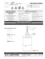
MAMMOTH
34W-57W Remote - LED
· Suitable for wet locations
IMPORTANT LISTINGS AND CERTIFICATIONS
Warning Hot Surface
Standard Installation
1/8” Allen Wrench
Waterproof Wire Connectors
Low Voltage
REMOTE WIRING
LED Driver
Remote driver installations require inter-connected
wiring between the LED and driver (by others).
Drivers have specific wiring requirements between
these components. Driver manufacturers regularly
recommend the following wiring details for such
installations:
• Do not exceed 50 foot overall wiring distance
using 12 gauge copper wire.
Failure to comply with specific wiring
requirements will void product warranty.
DRIVER HOUSING REQUIRED
Please refer to specified remote driver housing
documentation for detailed installation instructions.
REMOTE DRIVER HOUSINGS:
PM3DRM - Universal Power Module 3 Dual Remote
DRM - Dual Remote Wall Mount
PM2RM PM2DRM PM3RM PM3DRM
PM3DRM
PM2RM PM2DRM PM3RM PM3DRM
DRM
• Product must be installed by a qualified person in a manner
consistent with its intended use and in compliance with the
National Electrical Code, Canadian Electrical Code, and all Local
and Provincial Codes.
• Follow product label information and instructions.
• Qualified Personnel with appropriate personal protective
equipment must perform all servicing of this product.
• Before wiring to power supply and during servicing, turn off and
lock out power at fuse or circuit breaker before service.
• The use of accessory equipment not recommended by the
manufacturer or installed contrary to instructions may cause an
unsafe condition. The use of damaged components may cause
an unsafe condition and void product warranty.
IMPORTANT SAFETY INFORMATION - READ, FOLLOW, AND SAVE ALL
SAFETY AND INSTALLATION INSTRUCTIONS
• Do not block light emanating from product in whole or part,
as this may cause an unsafe condition.
• Never operate the fixture with missing or damaged lens.
Lens must be cleaned on regular basis.
• Entire fixture may become extremely hot. Do not touch hot
lens or fixture body.
• Replace LED assembly only with correct wattage and type
of power supply appropriate for LED assembly.
• All gaskets, o-rings and sealing surfaces must be kept clean
during installation and service; failure to do this may cause
an unsafe condition and void product warranty.
Heavy Duty
Mounting Ring
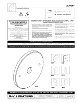
Canopy
IMPORTANT SAFETY INFORMATION - READ, FOLLOW, AND SAVE THESE INSTALLATION
INSTRUCTIONS
INSTRUCTIONS PERTAINING TO
A RISK OF FIRE, OR INJURY
TO PERSONS IMPORTANT
SAFETY INSTRUCTIONS
Lighted fixture is HOT!
WARNING - To reduce the risk of
FIRE OR INJURY TO PERSONS:
Turn off/unplug and allow to cool before
replacing lamp/LED.
Fixture gets HOT quickly!
Contact only switch/plug when
turning on.
Do not touch hot lens, guard, or enclosure.
Keep fixture away from materials that may burn.
Do not operate the luminaire fitting with a missing or
damaged shield. Do not touch the source at any time.
Use a soft cloth or gloves. Oil from skin may cause
damage.
SAVE THESE INSTRUCTIONS

40429 Brickyard Drive • Madera, CA 93636 • USA
559.438.5800 • FAX 559.438.5900
www.bklighting.com • [email protected]
B-K LIGHTING
RELEASE DATE
11/12/2021
REFERENCE NUMBER
INS-2321-01
Standard Installation
WIRING DIAGRAM
For use with 34-57 watt dimming driver.
Phase 1 - Rough In
Installation of Back box
1. Install Conduit (not included) to be used
with this product.
2. Install junction box (not included) so that
front face is flush with finished wall. Seal
building envelope as per NEC.
3. Connect box to conduit and pull wires for
connections (See wiring diagram).
Additional Info
• Please follow National and Local electrical codes for your area.
• 4” round cast box is provided with five (5) 1/2” threaded hubs for
conduit entry (4 on sides and one on back of box).
• Suitable for through wire.
• Suitable for installation into combustible materials.
• Rated for 90° C.
• Junction box, universal mounting ring screws, box mounting
hardware and gaskets (not included).
3. Mount fixture using two (2) #10-24 hex screws
to installed back box using a 1/8” allen wrench.
Seal building envelope as per NEC. Do not
overtighten.
GROUND IN HOUSING
LINE
COM
Remote
Driver
FIXTURE
DIM +
DIM -
FIXTURE
DIM +
DIM -
LINE
COM
Remote
Driver
Remote
Driver
Remote
Driver
FIXTURE +
FIXTURE -
FIXTURE +
FIXTURE -
GROUND
LED
FIXTURE +
FIXTURE -
LED
FIXTURE +
FIXTURE -
MAMMOTH
34W-57W Remote - LED
1. Install heavy duty mounting ring (mounting
ring supplied with fixture) using mounting
hardware (not included) onto back box. Align
fixture mounting holes to final mounting
position.
2. Make connections from remote driver and
external dimming controls to fixture and
module leads using proper wire connectors
(not included). Number of wires and
connections varies with wiring as per lighting
plan. See wiring diagrams.
Phase 2 - Finish Installation of Fixture
IMPORTANT SAFETY INFORMATION LISTED ON REVERSE
READ, FOLLOW, AND SAVE ALL SAFETY AND INSTALLATION INSTRUCTIONS

RELEASE DATE
11/12/2021
REFERENCE NUMBER
INS-2321-01
40429 Brickyard Drive • Madera, CA 93636 • USA
559.438.5800 • FAX 559.438.5900
www.bklighting.com • [email protected]
B-K LIGHTING
THIS DOCUMENT CONTAINS PROPRIETARY INFORMATION OF B-K LIGHTING, INC. AND ITS RECEIPT OR POSSESSION DOES NOT CONVEY ANY RIGHTS TO REPRODUCE, DISCLOSE ITS CONTENTS, OR TO MANUFACTURE, USE OR
SELL ANYTHING IT MAY DESCRIBE. REPRODUCTION, DISCLOSURE OR USE WITHOUT SPECIFIC WRITTEN AUTHORIZATION OF B-K LIGHTING, INC. IS STRICTLY FORBIDDEN.
LED BOARD / OPTICS
5-1/2” Diameter
Replacement
Warning Hot Surface
TOOLS
NEEDED: 5/32” Allen Wrench
Phillips Screwdriver
Small Pick Tool
Thermal Paste (Supplied)
9. Place cap on fixture and tighten set
screw. Tighten screw to 1/2 in-lbs. Top
of screw should sit flush with fixture cap.
Warning: Do not over tighten set screw. Doing
so will compromise o-ring seal and will void
warranty. Cap should be able to rotate without
force.
To Replace Components
1. Loosen three (3) #10-32 stainless steel set screws
on cap with a 5/32” allen wrench. Retain screws
in cap.
3. Unscrew #4-40 Phillips fasteners on optic holder
using Phillips screwdriver. Grasp optic holder and
gently pull upward to remove.
4. Carefully remove LED module from heatsink.
Do not pull on connector or wiring. Handle
with care.
5. Use small pick tool to push connector off LED
board through two small slots behind connector.
Once loose, lift connector upwards and off board.
Fragile! Do not pull on connector or wiring.
Handle with care.
7. Place new LED module onto heatsink. Press
connector straight downwards into slot on
module to snap into place.
Connector will only fit in one direction.
8. Reverse install optic holder, and then optic.
2. Remove optic by turning to the left to unlock
optic from optic holder tabs, and lift up.
6. Spread thin, even layer of thermal paste on back
of new LED module. Place new LED module onto
heatsink, lining up module with holes for screws.
Tighten two (2) #4-40 screws using a .050” allen
wrench to secure LED module to heatsink.
IMPORTANT SAFETY INFORMATION - READ, FOLLOW, AND SAVE THESE INSTALLATION
INSTRUCTIONS
/