Installation Instructions
For Anchoring (*)S3,(*)S4,(*)S5,(*)SA2, (*)SA4 AC
and (*)T3,(*)T4,(*)T5,(*)SH2, (*)SH4 HP Models From 1-5 Ton
Extreme Wind Condition Mounting Kit
Installation procedure for installing anchor
kit on split-system AC/HP models:
1. It is recommended that this kit be installed on the unit prior
to connecting refrigerant lines and electrical wiring. It may
be installed later if necessary.
2. Position the unit on the concrete pad or other structure and
install the base mounting brackets as illustrated below and
on reverse. The concrete screws provided may be used if
the unit is being anchored to a concrete pad or slab. If the
unit is mounted on a built-up roof or other structure, the
2" sheet metal screws provided may be used. It may be
bolted to an appropriate structure or framework using 1/4"
dia. minimum, grade 5 bolts and nuts if desired.
3. Install two anchors on each side of the corners of the unit
as shown for split-system AC/HP models (below).
Note: Fasteners used in the installation of this kit must be properly
installed and completely screwed in such that the head of the
fastener engages the bracket.
This kit is used to anchor Nordyne split-system, air conditioners
and heat pumps. Instructions for installing anchors on split-system
or packaged units are the same. Illustrations for anchoring split-
system units are shown below.
This anchor system is designed to meet the requirements of
Florida Building code 2007 and appropriate portions of ASCE
7-05 regarding the wind resistance and anchoring requirements
for mechanical equipment in Florida hurricane zones. This kit
will secure these units to an adequately designed concrete base
pad, metal frame or roof structure can withstand a 3 second gust
of a maximum wind speed of 150 MPH. Minimum concrete pad
requirements are given below.
KIT CONTENT
Base Mounting Bracket for models with metal base pan—
Qty 8
Base Mounting Bracket for models with composite base
pan— Qty 8
Tapcon
TM
Concrete Screw 1/4" x 1-3/4" — Qty 8
Hex Head SM Screw #14 x 2" — Qty 8
Installation Instructions
The kit has been updated to include four additional base mounting
brackets for use on units that have the composite base pan.
These brackets can be identifi ed by the number of holes in the
base of the bracket. Composite base pan mounting brackets
have 3 holes in the base.
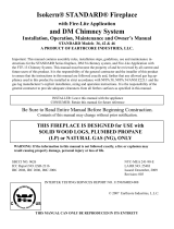
Bottom
Pan Lip
Tapcon
TM
Concrete Screw
1/4" x 1-3/4" Min.
or
#14 x 2" Hex
Head SM Screw
Drill 3/16" Dia.
Pilot Hole
Base
Mounting
Bracket
Concrete Slab:
Small Base Units: 34" x 34" x 3.5"* Min.
Large Base Units: 38" x 38" x 3.5"* Min.
Metal
Base Pan
Split-System AC and HP models
Mounting system depicted is suitable for mounting to 3000 PSI poured concrete, 1/8" minimum thickness
steel, or 1/4" minimum thickness aluminum at a height above ground up to 500 feet.
*Slab may be less than 3.5" but not less than 2" if allowed by all applicable codes