Page is loading ...

Thanks for purchasing one of our products.
Please read carefully the assembly instructions before the installation.
Do not discard this manual or any of the packaging material until the
unit has been completely assembled.
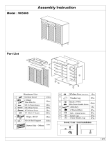
ASSEMBLY INSTRUCTIONS

A
Main Tabletop
C DB
F GE H
JI K L
PONM
Q
Bottom Left panel
- Top left panel
- Top Horizontal panel
Bottom Back panel
Front panel
Top Left Shelf panel
Top Left Back panel
Top Right Back panel
Top back panel
Top Partition panel
Top Middle panel
Top Right panel
Right Base Shelf panel
Top Right Shelf panel
Bottom Right panelRight Tabletop

MAIN PARTS LAYOUT
PART
QTY.
ITEM
1 44Pcs
Wooden Pin
Cam Lock &
Bolt Sets
11Sets
2
3
3Pcs
Screw - 4 x 25mm
4
15Pcs
Screw - 5 x 38mm
5 14Pcs
Screw Cap
6 11Pcs
Cam Lock Cap
7
2Pcs
Metal Plate EP5002
8
18Pcs
Screw - 3.5 x 16mm
9 4Pcs
L Bracket
10 6Pcs
Nail-in studs
11 3Pcs
Wooden Pin
12 1Pc
Management
(Grommet)
13
2Pcs
Z Bracket
14 4Pcs
Screw - 3 x 16mm
A
B
C
F
D
E
O
K
J
H
I
Q
P
L
M
M
N
(For reference):


1
- Install the wooden pins (1) into the panels (C), (D), (E), (F), (G), (H), (I), (J), (K), (L), (M),(N)
and (O) in the holes shown in the illustrations. Please pay attention to the correct holes to use
as other holes on the panels are intended for other hardware in other steps. DO NOT JOIN
ANY PANELS, JUST INSTALL THE PINS.
2
- Install the wooden pins (11) into the panel (E) in the holes shown in the illustration.
Please pay attention to the correct holes to use as other holes on the panel are
intended for other hardware in other steps.
1
C
D
E
M
M
N
I
J
K
H
L
G
O
F
1
E
11

3
4
First install bolts (2) into the panels (A), (B) and (G) in the holes indicated in the illustration, please note that on
(G) the bolts are installed on both sides of the panel. Then install the metal plate (7) on the panel (B) using
screws (8) as shown.
G
B
A
G
2
7
8
C
F
(BOTTOM)
(Front)
(Top)
4
5
- Assemble the panel (C) to panel (F) using screws (4) and cover the screw heads with (5) as
shown.

5
6
- First install the cam locks (2) into panels (C) and (D), and assemble the panel (A) as shown
and explained in page 4. Then using screws (8) install the L Brackets (9) to secure the panels
(A) and (F). Finally, cover the cam locks with (6).
This illustration shows the same
parts from step 13, but viewed
from a different angle (from the
right).
- Assemble the panel (D) to panel (F) using screws (4) and then cover the screw heads with (5)
as shown, then install the nail-in studs (10) to the bottom of the panels (C) and (D) as shown.
10
D
A
1st
3rd
2nd
C
F
D
F
C
4
2
5
6
8
9
10

7
9
x 2x 2
-
,then install the
nail-in studs (10)
E
B
E
2nd
2 8
8
- First insert and align the cam locks (2) into panel
(E), and assemble to panel (B) as shown and as
explained in page 4.Then secure the L Brackets
(9) to panel (B) using screws (8) as shown.
- Using screws (8), and from underneath the unit, attach the metal plate (7) from panel (B) to the
panel (A) as shown. Note that the right edge of panel (B) will align with the edge of panel (A).
B
A
8
(This illustration shows the
same parts from steps 6 and 8,
but viewed in normal upright
position)
x 2

10
11
12
12
- Install the Grommet (12) as shown.
- First install the cam locks (2) in to panel (O) and assemble it to panel (G) as shown and as
explained in page 4. Please note that the cam locks go facing towards the outside of the
panel. Then cover the cam locks with (6).
O
G
2
6

12
13
- Assemble the panels (K) and (L) using screw (4) as shown.
L
K
4
- Assemble the panel (J) to panel (L) using screw (4) as shown.
J
L
4

14
15
- First install and align the cam locks (2) into panels (K) and (J) and then assemble the panel (G)
as shown and as explained in page 4.
G
K
J
2
- Slide the panel (P) into the groves of panels (G) and (L) as shown.
This illustration shows the
same parts from step 14, but
viewed from a different angle
(from the left).
P
L
G

16
17
- Using screws (4), assemble the panel (H) to panels (G) and (L), the panels (M) to the panel (J)
in the middle, and the panel (N) to (J) on the right as shown.
H
M
M
N
L
G
J
4
- Slide the panel (Q) into the groves of panels (G), (J) and (N) as shown.
Q
This illustration shows the same
parts from step 16, but viewed
from a different angle (from the
right).
J
G
N

18
19
- Assemble the panel (I) to the panels (N), (M) and (G) using screws (4), and then cover the
screw heads with (5).
I
M
M
N
G
5
4
- Attach the Z bracket (13) to the upper left and lower right corner of the
back panel (N) using screws (14)as shown.
13
14
This illustration shows the same
parts from step 18, but viewed in
upright position from their back.

20
First, and preferable with the help of another person, place the parts assembled in step 12 over the panel (A),
then using screws (3), and from underneath the panel (A), secure the panels (H) and (N) to panel (A) as shown.
DONE! Before you start using the unit, make sure that all the screws, bolts, cam
locks, etc. are properly tightened, and read all the warnings in the next page.
Enjoy your new unit!
H
N
A
3

/