Arctic Air 297096700 (0603) User manual
- Category
- Freezers
- Type
- User manual
This manual is also suitable for

ARCTIC AIR
COMMERCIAL
REFRIGERATOR/FREEZER
Table of Contents
Product Registration ........................................... 2
Important Safety Instructions ............................. 2
Electrical Information .......................................... 2-3
Installation and Setup ......................................... 3-4
Appliance Start-Up .............................................. 5
Features ............................................................... 5-6
Routine Maintenance .......................................... 6-7
Reversing Door .................................................... 7-8
Energy Conservation Measures ......................... 8
Avoid Service Checklist ...................................... 9-10
Wiring Diagram .................................................... 11
If You Need Service ............................................. 12
Warranty ............................................................... 13
P/N: 297096700 (0603)

Product Registration
The information contained within this Owner's Guide
will instruct you on how to properly operate and care
for your product. Please read through the information
contained in your literature pack to learn more about
your new appliance. The serial plate is located on the
inside left wall of unit.
Record Your Model and Serial Numbers
Record the Model No. and Serial No. of this appliance
in the space provided below.
Model No.:
Serial No.:
Register Your Product
The self-addressed PRODUCT REGISTRATION CARD
(shown above) should be filled in completely, signed
and returned to the address provided.
,, Remove the door(s) of any appliance that is not in use,
even if it is being discarded.
,, Remove and discard any spacers used to secure the
shelves during shipping. Small objects are a choke
Proper Disposal of Your
Refrigerator/Freezer
Risk of child entrapment.
Child entrapment and suffocation are not
problems of the past.Junked or abandoned
refrigerators or freezer are stilldangerous
-- even if they will sit for "just a few days." If
you are getting rid of your old refrigerator or
freezer, please follow the instructions below
to help prevent accidents.
BEFORE YOU THROW AWAY YOUR
OLD REFRIGERATOR/FREEZER:
• Remove doors.
. Leave shelves in
place so children
may not easily
climb inside.
Important Safety Instructions
Read all instructions before using this appliance.
For Your Safety
Do not store or use gasoline or other flammable
vapors and liquids in the vicinity of this or any other
appliance. Read product labels for flammability and
other warnings.
r! Wkvlvf±1;t_ll_ [q
Child Safety
,, Destroy carton, plastic bags, and any exterior
wrapping material immediately after the freezer is
unpacked. Children should never use these items to
play. Cartons covered with rugs, bedspreads, plastic
sheets or stretch wrap may become airtight
chambers, and can quickly cause suffocation.
,, Remove all staples from the carton. Staples can
cause severe cuts, and destroy finishes if they come
in contact with other appliances or furniture.
,, An empty, discarded ice box, refrigerator, or freezer is
a very dangerous attraction to children.
hazard to children.
Electrical Information
These guidelines must be followed to ensure that
safety mechanisms in the design of this appliance
will operate properly.
Avoid fire hazard or
electric shock. Do not use an extensior
cord or an adapter plug. Do not remow
any prong from the power cord.
Grounding type
wall receptacle
_0 not under
J I I any circumstances
J _ I_ cut, remove,
I _ I _ or bypass
I / ' _ W the grounding prong

• Refer to the serial plate for correct electrical rating.
The power cord of the appliance is equipped with a
three-prong grounding plug for protection against shock
hazards. It must be plugged directly into its own
properly grounded three-prong receptacle, protected
with a 15 amp time delay fuse or circuit breaker. The
receptacle must be installed in accordance with the
local codes and ordinances. Consult a qualified
electrician. Receptacles with Ground Fault Circuit
Interrupters (GFCI) are NOT RECOMMENDED. DO
NOT USE AN EXTENSION CORD OR AN ADAPTER
PLUG.
• If the voltage varies by 10 percent or more, appliance
performance may be affected. Operating the appliance
with insufficient power can damage the motor. Such
damage is not covered under the warranty. If you suspect
your voltage is high or low, consult your power company
for testing.
• To prevent the appliance from being turned off
accidentally, do not plug the unit into an outlet controlled
by a wall switch or pull cord.
• DO NOT pinch, knot, or bend the power cord in any
manner.
Other Precautions
• NEVER unplug the appliance by pulling on the power cord.
Always grip the plug firmly and pull straight out from the
receptacle.
• To avoid electrical shock, unplug the appliance before
cleaning.
NOTE: Turning the control to "OFF" turns off the
compressor but does not disconnect power to other
electrical components.
TOOLS NEEDED
You will need the following tools to assemble and install the
casters to the unit.
3/8" AND 1/2" iNCH ADJUSTABLE WRENCH
SOCKET WRENCH OR PLIERS
1/2 _'iNCH FIXED
WRENCH
UNCRATING AND SET-UP
• Remove carton and all loose parts from inside of the unit.
• Carefully tip the unit onto its back with the help of an
assistant. Lay the unit gently to rest on blocks to avoid
damaging the condensate drain hose and the plastic
raceway that covers the evaporator tubing on the back of
the cabinet.
• Remove and discard the wood skid from the bottom and
the four (4) screws using a 3/8" socket wrench (see Fig.
1).
• Using a large adjustable wrench, remove and discard the
two (2) black plastic leg levelers by turning it
counterclockwise (see Fig. 2).
• For glass door models only, remove bottom door support
bracket and screw opposite the door hinge using a 3/8"
socket wrench (see Fig. 3).
/J"
SCREWS !
, LEG LEVELER
CASTER INSTALLATION AND SET-UP "
Inspect the underside of the cabinet and packaging for WOOD SKID--'''''''_
damage such as a fork truck can cause. If hidden damage is Figure 1
found after uncrating, immediately call the delivery carrier
and request an inspection. Retain all packaging and crating
materials until the inspection is complete.
DOOR . .......
SUPPORT .... "'_._
BRACKET_
Figure 3 \\--..
PARTS AND ACCESSORIES
Check to make sure that you have received the box
containing all of the components listed below.
D
F
Figure 2
A CASTER RAIL (2) E WASHER (4)
B LOCKING NUT (8) F SPACER PLATE (2)
C CARRIAGE BOLT (8) G SWIVEL CASTER (2)
D BOLT (4) H FIXED CASTER W/BRAKE (2)

FRONT FIXED CASTER INSTALLATION
• Put two (2) carriage bolts through the rear (non-brake)
side of the fixed caster and hold the carriage bolts loosely
in place by threading several turns on each of the locking
nuts. Do not tighten the bolts yet.
• Hold the caster in position, insert the carriage bolt heads
into slots A & B near the front of the caster rail and slide
the caster back.
• Insert the two (2) front carriage bolts thru the top side of
the caster rail and then thru the front holes on the caster.
Attach locking nuts to each.
• Tighten all locking nuts securely using a 1/2 inch wrench
(see Fig. 4).
• Repeat the same procedure for the other fixed caster.
BRAKE
FRONTOF
CASTER RAIL_,_I _
• LOCKING NUTS
i(_ _ FIXED CASTER
CARRIAGE
BOLTS
CARRIAGE BOLTS Figure4
SLOTS A&B
CASTER RAIL INSTALLATION
• Place a washer onto one of the four long bolts and slide
bolt through the hole located just behind the fixed caster
at the front of caster rail.
• Align the caster rail assembly with the right hand side of
the unit. Make sure the fixed caster is positioned toward
the front of the unit.
• Align the bolt with the threaded hole in the front right foot
pad of the unit. Thread the bolt into the hole until finger
tight (see Fig. 5).
WASHER_
BOLT _
Figure 5
WASHER
BOLT
REAR SWIVEL CASTER INSTALLATION
• Place a washer on one of the four long bolts and then feed
the bolt through the hole in one of the swivel casters (see
Fig. 6).
• Next, insert that same caster bolt through the hole on the
metal spacer plate and then thru the rear hole of the caster
rail (see Fig. 7).
• Thread the caster bolt into the hole in the bottom-most
foot pad on the unit.
• Tighten both top and bottom bolts securely using a 1/2
inch fixed or socket wrench.
• Repeat the same procedure on the left hand side. After
installation, carefully tip the unit up with the help of an
assistant.
Washer J"_
Swivel _ !
Caster ..... --_
Figure 6
j_
_i?_, " :%.
Figure7
Appliance Placement
Leave a one (1) inch space on all sides and the back of the
cabinet for ease of installation, proper air circulation and
electrical connections. DO NOT block the front grill on
the lower front of your appliance. Sufficient air circulation
is essential for the proper operation of your appliance.
Choose a place that is near a grounded electrical outlet. For
the most efficient operation, the appliance should be located
where surrounding temperatures will not drop below 40°F
(5°C) or exceed 110°F (43°C). Additional compressor heaters
are not recommended.
Insulation
The insulated space of this cabinet is sealed to
maintain peak efficiency. Holes drilled in the cabinet
may destroy that seal and damage electrical wiring
located in the insulated space.
DAMAGED ELECTRICAL WIRING OR WET
INSULATION CAUSED BY DRILLING WILL VOID THE
WARRANTY.

Appliance Start-Up
Once the appliance has been located in its permanent
location and the proper power and grounding has
been provided, the following items must be checked or
completed:
Cool Down Period
For safe food storage, allow 24 hours for the appliance
to cool down completely before loading with food.
The appliance will run continuously for the first several
hours. Do not place any food in the appliance until
after the first 24 hours of operation.
Thermostat Settings
The appliance is shipped from the factory with the
thermostat set at about the mid-point of the operating
range. Adjustments colder or warmer can be made
after the appliance has been running for at least 8
hours. Allow at least 8 hours for temperature
stabilization before re-adjusting the thermostat.
Defrost Setting
The appliance is designed to defrost automatically
every 12 hours. To set the time of defrost, wait until
the desired time to defrost. With the notch on the
timer knob aligned with the line on the bracket
(Figure A), turn the defrost timer knob clockwise
slowly. The timer will click several times, then once
loudly, at which point the defrost cycle begins. The
timer knob will advance through the defrost cycle,
then click loudly at the end of the cycle (Figure B).
The appliance will defrost automatically every 12 hours
after the first defrost cycle.
For example, to set the appliance to defrost at 10:00
a.m., turn the timer knob clockwise at 10:00 a.m. until
the timer clicks loudly.The appliance will defrost daily
at 10:00 a.m. and again12 hours later at 10:00 p.m.
Note: The product interior temperature will rise during
the defrost cycle every 12 hours.
DefrostTimer Back of Unit
Figure A
Position of knob
before turning clockwise
to start defrost cycle.
Figure B
Position of knob
at end of defrost cycle.
Features
Heavy duty epoxy powder coated adjustable shelving
NSF certified top mounted evaporator
2-1/2" urethane foam cabinet insulation
Torsion spring door closer
Heavy duty swivel casters
17 watt fluorescent lamp
Removable stainless steel drain cover
Adjustable temperature control
NSF certified interior
Stainless steel evaporator housing
Stainless steel toe plate
Heavy duty commercially rated electrical harness
Heavy duty removable stainless steel shelf supports
Shallow
Shelves
(2) Regular
BoSom
The appliance is provided with 4 shelves. One goes or
the floor of the cabinet and the other 3 are placed in
the metal side supports wherever they are needed. Th_
shallow shelf goes in the upper position.

4SwivelCasters
Theappliancecomeswith4swivelcasters;2with
locksforfrontofunitand2withoutlocks,fortheback
oftheunit,Thecastersallowtheappliancetobe
movedwithease,andthenlockedintoplaceupon
finaldestination,(Refertopage3forinstructions,)
ReversibleDoorLock
Theappliancecomeswithanoutercabinetmounted
doorlockandtwokeys.Thelockcanbemountedon
eithersideoftheappliancedependingonwhichside
thedoorswingsopen,Adoormountedlockguard
hasbeenprovidedforaddedsecurity.(Refertopage7
forinstructions.)
InteriorThermometer
Theappliancecomeswithathermometertoshow
internaltemperatures.Thethermometeristobehung
fromthetopadjustableshelfontherighthandside,
ReversibleDoor
Thedoorcanbereversed(SeeRoutineMaintenance
section)toprovideeitheraright-handswingoraleft-
handswing,
AdjustableTemperatureControl
Theadjustablethermostatcontrolislocatedonthetop
leftpanelinsidetheunit,
InteriorLight
Theapplianceisequippedwitha40wattbulbthat
lightsupwhenthedoorisopened.Ifbulbgoesbad
replacewithbulbofsametypeandwattage.Thisisa
specialbulbwithashatterproofcoating.UseanNSF
certifiedbulbofthesametypeandwattage(canbe
orderedfromyourArcticAirServiceCenterat
1-800-490-9574/ PIN 2163600900).
Routine Maintenance
Cleaning the Interior
Be sure to turn the temperature control to off and
unplug the electrical cord, Wash the inside surface of
the storage area with warm water and baking soda
solution (about one tablespoon of baking soda per
quart of water). Rinse thoroughly with clean, warm
water and wipe dry. The procedure can also be used
for cleaning the door gasket. Wipe the stainless steel
cover plates with Magic Clean Stainless Steel Cleaner
(can be ordered from your Arctic Air Service Center at
1-800-490-9574 / PIN 218490900) or some other
stainless steel cleaner.
Cleaning the Exterior
Wipe the textured cabinet exterior occasionally with a
cloth dampened in mild detergent and water, rinse
and wipe dry with a soft cloth, Wipe the stainless
steel door plate and toe grill with Magic Clean
Stainless Steel Cleaner or some other stainless steel
cleaner. Do not use razor blades or other sharp
instruments that can scratch the appliance surface
when removing adhesive labels. Any glue left from the
tape can be removed with a mixture of warm water
and mild detergent or touch the residue with the
sticky side of tape already removed, DO NOT REMOVE
THE SERIAL PLATE,

CondensatePan
Thecondensatepanisinafixedpositionandmustnot
beremovedfromunderthecabinet.Ifthepanis
removed,condensatewilldripontothefloor.
Reversing Door
This appliance features a door that can provide either
a left hand or right hand opening. It comes from the
factory in the right hand position.
Follow these steps to reverse the opening:
1, With the appliance in a standing upright position,
open the door and remove the toe plate (2 screws
in the upper corners).
2, Slightly loosen the two hex spacers that the toe
plate screws were screwed into.
Top
(2)Hex Head
Spacers
(2) Screws
Toe Plate Door
,
.
Remove top screw from bottom hinge. Remove toF
screw from opposite side of appliance.
Cabinet
Spacer
(slightly Ioc sened)
Slide bottom hinge onto hex spacer and attach top
screw to cabinet. Retighten both hex spacers.
Bottom
(
Hole
Screw
3. Holding door securely closed, remove three (3) hex
head screws from the top hinge and flat spacer.
4. Lift appliance door off of bottom hinge and set
aside in a safe place (so it does not fall)
7. Remove the top hinge assembly and the bottom
spacer from the door and reverse their position,
making sure the pegs are properly seated in the
peg holes.
8. Rotate the door 18(7 and re-install on bottom
hinge. Hold door in closed position.
Screws
Top
Flat
9r
Top Hin! _1_ (3) Hex
Head
Screws
_ Spacer
Hole

9, Rotatethetophingetoalignthemounting
holes.Re-positionthefiatspacerbetweenthehinge
andcabinetandinstallthethree(3)hexhead
screws,
10,Installholeplugsineachofthehingeholeson
oppositesideofcabinet,
11.Re-installtoeplatewithtwo(2)screws,
Door Lock
Note : The lock strike should angle out and away
from the cabinet,
1. Install the lock strike on the lock side of the
cabinet, using the three (3) tamper resistant
screws, Install the three remaining buttons in the
holes on the opposite side of the cabinet,
2, Install the lock guard in the side of the door
cabinet by installing the two screws into the
corresponding screw holes,
The tamper resistant screws cannot
be removed after the lock strike is secured to the
cabinet.
Energy Conservation Measures
The appliance is designed for efficiency with heavy
foam insulation. However, there are things that the
user can do to maintain the appliance in operating
condition:
1. Do not operate the appliance any colder than
necessary to maintain safe, product storage
temperatures.
2, Make sure the appliance is located to prevent
direct exposure to sunlight, air ducts, etc,
3, Keep the door closed except for normal use,
Inspect the door often to see that it self-closes and
the gasket is in good condition,
4, Do not overstock the product in the cabinet
because it will block the normal air flow,
5, Have at least annual inspections by a qualified
service company to see that the fan motor is
functioning properly and that the refrigerant charge
is correct.
6, This appliance operates more efficiently in a cooler
ambient than in a hot ambient. Try to maintain an
ambient below 80°F (2-fC) and 65% RH for
maximum efficiency.
Lock Strike --
Cabinet Door
(3)Tamper
Resistant
Screws
Head Screws
Lock

Avoid Service Check st
Before calling for service, review this list. It may save you both time and expense. This list
includes common occurrences that are not the result of defective workmanship or materials in
this appliance.
OCCURRENCE
SOLUTION
APPLIANCE DOES NOT RUN
• Appliance may be in defrost cycle, and the compressor or fan will not run.
, Temperature control is in the OFF position.
, Appliance may not be plugged in or plug may be loose. Be sure plug is tightly
pushed into electrical outlet.
, Fuse has blown, orcircuitbreakerhastripped. Check/reset circuit breakerorreplacc
fuse with 15 amp. time delay fuse.
, Power outage. Check lights. Call local electric company.
Appliance runs too much or too
long.
, Room or outside weather is hot. It is normal for the appliance to work harder under
these conditions.
, Appliance had recently been disconnected for a period of time. Appliance requires
24 hours to cool down completely.
Large amounts of warm or hot food have been stored recently. Warm food will
cause the appliance to run more until the desired temperature is reached.
, Door is kept open too long or too frequently. Warm air enters the appliance every
time the door is opened. Open the door less often.
, Appliance door may be slightly open. See Occurrence section "Door Problems."
• Temperature control is set too cold. Turn the control knob to a warmer setting.
Allow several hours for the temperature to stabilize.
• Appliance gasket is dirty, worn, cracked, or poorly fitted. Clean or change gasket.
Leaks in the door seal will cause appliance to run longer in order to maintain desired
temperature.
Temperatures inside the
appliance are too cold.
• Temperature control is set too cold. Turn the control to a warmer setting. Allow
several hours for the temperature to stabilize.
Temperatures inside the
appliance are too warm.
, Temperature control is set too warm. Turn the control to a colder setting. Allow
several hours for the temperature to stabilize.
• Door is kept open too long or is opened too frequently. Warm air enters the
appliance every time the door is opened. Open the door less often.
• Door may be open slightly. See Occurrence section "Door Problems."
Large amounts of warm or hot food may have been stored recently. Wait until the
appliance has had a chance to reach its selected temperature.
Temperature of external
appliance surface is warm.
, Appliance has recently been disconnected for a period of time. Appliance requires
24 hours to cool down completely.
• The product internal temperature will rise during the defrost cycle.
Appliance cabinet is warm to the touch. Appliance is operating normally, removing
warm air form the inside.

OCCURRENCE SOLUTION
SOUND AND NOISE
Louder sound levels whenever
appliance is on.
Today's appliances have increased storage capacity and a more even temperature
They require a high speed compressor. This is normal.
Louder sound levels when
compressor comes on.
Appliance operates at higher pressures during the start ofthe ON cycle. This is normal
Sound will level off or disappear as appliance continues to run.
Popping or cracking sound
when compressor comes on.
Metal parts undergo expansion and contraction, as in hot water pipes. This is normal.
Sound will level off or disappear as appliance continues to run.
Bubbling or gurgling sound,
like water boiling.
Refrigerant (used to cool appliance) is circulating throughout the system. This is
normal.
Vibrating or rattling noise.
Appliance is not level. It rocks on the floor when it is moved slightly. Install leveling
washers to shim up the appliance.
Floor is uneven or weak. Appliance rocks on the floor when it is moved slightly. Be
sure floor can adequately support appliance.
• Appliance is touching the wall. Re-level the appliance or move appliance slightly.
WATER/MOISTURE/FROST
INSIDE APPLIANCE
Moisture forms on inside
appliance walls.
WATER/MOISTURE/FROST
OUTSIDE APPLIANCE
Moisture forms on outside of
appliance.
ODORIN APPLIANCE
DOOR PROBLEMS
Door will not close.
. Weather is hot and humid, which increases internal rate of frost build-up. This is
normal.
. Door is slightly open. See Occurrence section "Door Problems."
. Door is kept open too long or is opened too frequently. Open the door less often.
• Door is slightly open, causing the cold air from inside the appliance to meet warm
moist air from outside. See Occurrence section "Door Problems."
. Interior needs to be cleaned. Clean interior with sponge, warm water, and baking
soda.
. Foods with strong odors are in the appliance. Cover the food tightly.
• Appliance is not level. It rocks on the floor when it is moved slightly. This condition
can force the cabinet out of square and misalign the door.
• Floor is uneven or weak.
LAMPIS NOTON
. Lamp is burned out. Follow directions under "Interior Light" in Appliance Features.
. No electric current is reaching the appliance. See Occurrence section "Appliance
Does Not Run."
10

Wiring Diagrams
Door
Switch
EC79
Refrigerator Electrical Circuit
Powel _
Run
Capacitor_._ i/ H
Compressor _ I//-Ye'
Controller_. -L_._C_'_ L _ Wh
i " N
C10
iMPORTANT
If any green grounding wires are removed
during servicing, they must be returned to
their original position and properly secured.
Freezer Electrical Circuit
Power
Yellow
r...................Overload
PTC Starter
White
Defrost Heater
/
_e Red _ •
Door _J
Interior
Switch
Light
ECS0
C29
Capacitor
IMPORTANT
If any green grounding wires are removed
during servicing, they must be returned to
their original position and properly secured,
11

If You Need Service
Avoid Unnecessary Cost and Inconvenience
Make a few simple checks before calling for service. Common occurrences and their solutions can be found
in the "Avoid Service Checklist" included in this owner's guide.
If Service Is Necessary
Keep your bill of sale, delivery slip, or some other appropriate payment record. The date on the bill
establishes the warranty period should service be required. Ifservice is performed, it is in your best interest
to obtain and keep all receipts. This written warranty gives you specific legal rights. You may also have other
rights that vary from state to state. Service under this warranty must be obtained by contacting the
Arctic Air Customer Service Center
In the United States • 800,490,9574
In Canada: 866,294,9911
12

ARCTIC AIR COMMERCIAL REFRIGERATOR/FREEZER
WARRANTY
A,
B,
C,
D,
E,
ARCTIC AIR (Division of Broich Enterprises, Inc.) warrants every new refrigerator and freezer to be
free from defects in material or workmanship for a period ofone (1) year (except as noted in the Special
Mobile Use Warranty below) from the earliest of either: 1) the date of original purchase or; 2) fifteen (15)
months after the manufacturer's ship date of the product ( warranty period ).
This warranty provides:
PARTS WARRANTY
ARCTIC AIR will, at its option, repair or replace any part(s), that are found defective during the warranty
period. In addition, ARCTIC AIRwarrants that the compressor shall be free from defects for an additional
four (4) years beyond the expiration of the warranty period or for a total period offive (5) years.
Warranty replacement parts must be arranged by calling the Customer Service Center at 1-800-490-9574
( in the United States and Puerto Rico ) and 1-866-294-9911 ( in Canada ).
LABOR WARRANTY
ARCTIC AIR will, at its option, provide or pay for the labor to repair or replace the part(s) or product defect
during the warranty period. Warranty labor must be arranged by calling the Customer Service Center at
1-800-490-9574 ( in the United States and Puerto Rico ) and 1-866-294-9911 ( in Canada ).
SPECIAL MOBILE USE WARRANTY
ARCTIC AIRwarrants every new refrigerator and freezer operated by a concessionaire or vendor in a
trailer, motorized vehicle or at varying locations for a period of one (1) year for the part(s) andninety
(90) days for labor to repair or replace, at Arctic Air's option, the warranty part(s). In addition,ARCTiC
AIR warrants that the compressor shall be free from defects for a total period offive ( 5 ) years. This
warranty will be effective with the earliest of either: 1) the date of original purchase or ; 2) fifteen (15 )
months after the manufacturer's ship date of the product. Any labor to remove or expose or make the
refrigerator or freezer available for service under this warranty shall be at the user's expense.
CONDITIONS
Service under this warranty must be performed by a preferred service company arranged by the
Customer Service Center at 1-800-490-9574 ( in the United States and Puerto Rico ) and
1-866-294-9911 ( in Canada ). The user must give the preferred service company prompt notice and
access to the product when service is needed
LIMITATIONSAND EXCLUSIVE WARRANTY
Normal wear and tear and gradual deterioration is excluded from this warranty. This parts and labor
warranty is the sole and exclusive warranty remedy offered byARCTIC AIR ALL OTHER WARRANTIES,
EITHER EXPRESS OR IMPLIED, ARISING UNDER LAW OR EQUITY OR CUSTOM OF THE TRADE
INCLUDING BUT NOT LIMITED TO WARRANTIES OR MERCHANTABILITY OR FITNESS FOR A
PARTICULAR PURPOSE ARE EXCLUDED. NEITHER ARCTIC AIR NOR ITS SERVICING AGENT SHALL
BE LIABLE FORANY INCIDENTAL OR CONSEQUENTIAL LOSS OR DAMAGES (INCLUDING BUT NOT
LIMITED TO FOOD OR PRODUCT LOSS, PERSONAL INJURY OR PROPERTY DAMAGE) WHETHER
BASED ON CONTRACT OR TORT (INCLUDING NEGLIGENCE AND STRICT LIABILITY) ARISING OUT
OF THE EQUIPMENT OR SERVICE PROVIDED HEREUNDER. THIS WARRANTY DOES NOT APPLY
ARCTIC AIR PRODUCTS SOLD OUTSIDE THE UNITED STATES, CANADA, OR PUERTO RICO. THIS
WARRANTY DOES NOT COVER:
FREIGHT DAMAGE
FOOD LOSS
NON-FACTORYAPPROVED REVISIONS OR MODIFICATIONS
13
-
 1
1
-
 2
2
-
 3
3
-
 4
4
-
 5
5
-
 6
6
-
 7
7
-
 8
8
-
 9
9
-
 10
10
-
 11
11
-
 12
12
-
 13
13
Arctic Air 297096700 (0603) User manual
- Category
- Freezers
- Type
- User manual
- This manual is also suitable for
Ask a question and I''ll find the answer in the document
Finding information in a document is now easier with AI
Related papers
-
Arctic Air GDR22CWRF1 User manual
-
 Arctic Air R22CW13 Owner's manual
-
Crosley F22CWF4 User manual
-
 Arctic Air Artic Air Commerical Glass Door Refrigerator User manual
-
 Arctic Air CF207 Owner's manual
-
Crosley ST20G2 Owner's manual
-
 Arctic Air R22CWF6 Owner's manual
-
 Arctic Air GDR22CWLF2 User manual
-
 Arctic Air GDR22CWR User manual
-
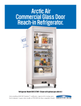 Arctic Air GDR22CWR User manual
Other documents
-
Greenlee Caster Installation - Job Box Manual User manual
-
Greenlee Caster Installatio - Job Box User manual
-
Husky HMT405BDLX16 Operating instructions
-
Husky H4116TR Installation guide
-
Gibson KCGM180RQYA Owner's manual
-
Kenmore 795.6991 User manual
-
Kenmore 795.6397 User manual
-
Frigidaire FFFC20M4TW Owner's manual
-
Kelvinator KGM220RHY3 Owner's manual
-
Frigidaire FCGM181RQB Complete Owner's Guide (English)


