Page is loading ...
ND-71762(E)
ISSUE 2
No.7 CCIS System Manual
AUGUST, 2002
NEC Corporation
To view the latest issue of this document go to NEC Knowledgebase @ http://www.kbase.cns.nec.com.au &search for NEC-7141

LIABILITY DISCLAIMER
NEC Corporation reserves the right to change the specifications,
functions, or features, at any time, without notice.
NEC Corporation has prepared this document for use by its employ-
ees and customers. The information contained herein is the property
of NEC Corporation and shall not be reproduced without prior written
approval from NEC Corporation.
All brand names and product names on this document are trade-
marks or registered trademarks of their respective companies.
Copyright 2002
NEC Corporation

ND-71762 (E) PRODUCT LIABILITY
PL- 1
Issue 2
PRODUCT LIABILITY
BEFORE THE USE OF THIS MANUAL
1. FOR SAFETY USE
Here explains the safety use for the customer, which prevents danger to the life and damage to the property ac-
cidentally. The following are symbols and their meanings. Please read the following carefully before using this
manual.
SYMBOLS
DESCRIPTION
DANGER
This symbol indicates danger. You might be involved in a situation that
could cause deadly and bodily injury if you take wrong action.
WARNING
This symbol indicates warning. You might be involved in a situation that
could cause bodily injury and serious system fault if you take wrong ac-
tion.
ATTENTION
This symbol indicates attention. The system might not acheive its perfor-
mance or lead to the system stall if you take wrong action.
This telephone system is designed for use in the country NEC provides and can not be used in any other country.
If system-down, malfunction, defects, and external factors (such as electricity failure) cause profit loss indirectly, NEC does
not take any responsibilities for the profit loss.
We pay careful attention to making this manual, however, when you find mistakes on this manual, notify to NEC.
Contact the supplier or the service technician if the system needs repairs and installation.
Please read all the manuals related to your system carefully.

PRODUCT LIABILITY ND-71762 (E)
PL- 2
Issue 2
PRODUCT LIABILITY
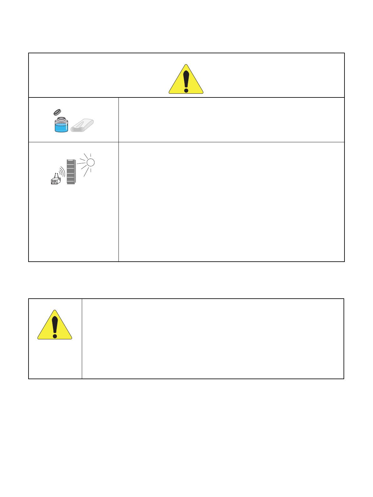
2. NOTICE WHEN USED
2.1 Consideration of PBX, Power-related Equipment and Peripheral Equipment
This item describes the consideration before using PBX, the power-related equipment, and the peripheral equip-
ment (such as console, MDF, DAU, telephone, PC, printer, etc).
Preserve the following:
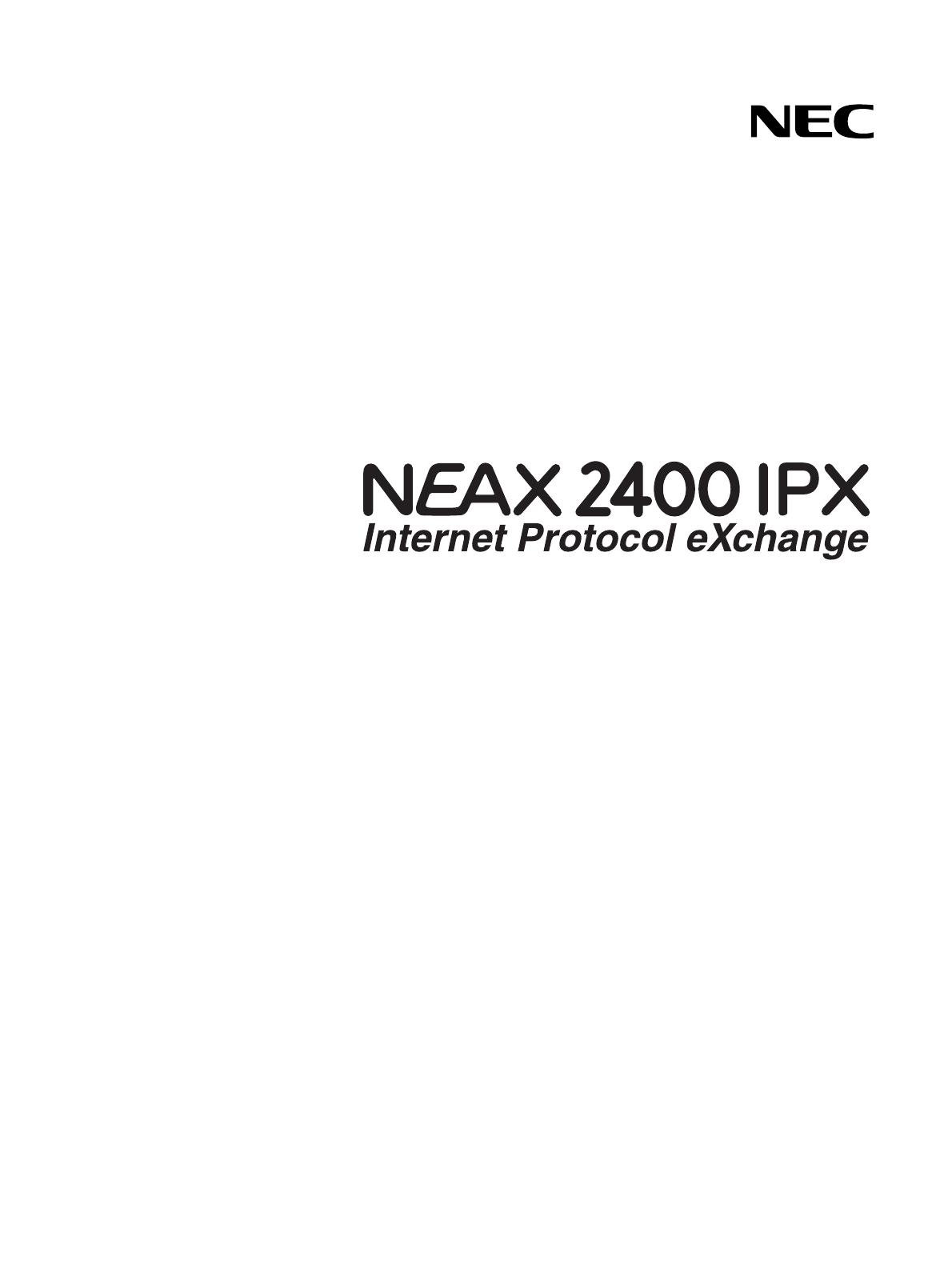
DANGER
When the system gives off smoke or burning smell, it might cause a fire, an electric
shock, or a failure if the system keeps operating. Turn off the power and confirm the
smoke disappears, and then contact supplier.
If equipment (such as PBX, Main Power, cabinet, and peripheral equipment) fall down
and be broken, turn off the power, and then contact the supplier.
If the inside of PBX or Main Power is wet by liquid such as water, turn off the power.
It might cause a fire, an electric shock, or a failure if the system keeps operating.
Do not touch the internal parts of Main Power for the purpose of disassembly and re-
modeling. It might cause a fire, an electric shock, or a failure.
(NEC does not take any responsibilities if the system or the equipment is disassembled
or remodeled.)
Do not put any container (such as vase, cup, and cosmetics) on Main Power and periph-
eral equipment. It might cause a fire, an electric shock, or a failure.
PWR

ND-71762 (E) PRODUCT LIABILITY
PL- 3
Issue 2
PRODUCT LIABILITY
DANGER
Do not damage, remake, forcefully bend, forcefully extract, nor forcefully twist an elec-
tric code and a wiring to/from PBX, Main Power and peripheral equipment. It might
cause a fire, an electric shock, or a failure. If the wiring is damaged, ask the supplier to
fix it.
Insert the electric plug into the outlet properly. Confirm no dust is on the blade of plug;
it might cause a fire.
Do not use other than the power designated when installed.
Do not try to fix or move Main Power by yourselves without the supplier or service tech-
nician’s help. Please ask them when the repair or the movement is necessary.
Do not put any metal or combustible object into a vent of PBX, Main Power, and the
peripheral equipment. If the object is in those equipment, turn off the power and ask the
supplier. It might cause a fire, an electric shock, or a failure if the system keeps operat-
ing.
Be careful of using the display part which the peripheral equipment has. In the case of
liquid crystal, the liquid is leaked and causes harm to human body and systems.
Before connecting customer-provided equipment (such as the other company products)
with NEC products such as PBX and peripheral equipment, ask the supplier and make
sure your equipment is compatible with NEC product. If it is not confirmed, do not con-
nect them. It might cause a fire or an electric shock.
dust
PWR
PWR
?
PRODUCT LIABILITY ND-71762 (E)
PL- 4
Issue 2
PRODUCT LIABILITY
WARNING
Fix the equipment. Do not put any object on PBX and Main Power; it might be danger-
ous if the object should fall down.
When plugging off a plug, be sure to grip the plug and extract it. If you grip the code
and extract it, it might cause a fire and an electric shock.
If a fault is considered as the lightening cause, ask the supplier.
Other than fulfilling the appropriate humidity and temperature, it is necessary to consid-
er the maintenance operation and the all-time ventilation in non-loading operation dur-
ing day-off and night. For example, when the height above floor is 1 m (3.281 feet), the
temperature should be from 20 to 25 °C (68 to 77 °F ) and the humidity should be more
or less 50 %.
ND-71762 (E) PRODUCT LIABILITY
PL- 5
Issue 2
PRODUCT LIABILITY
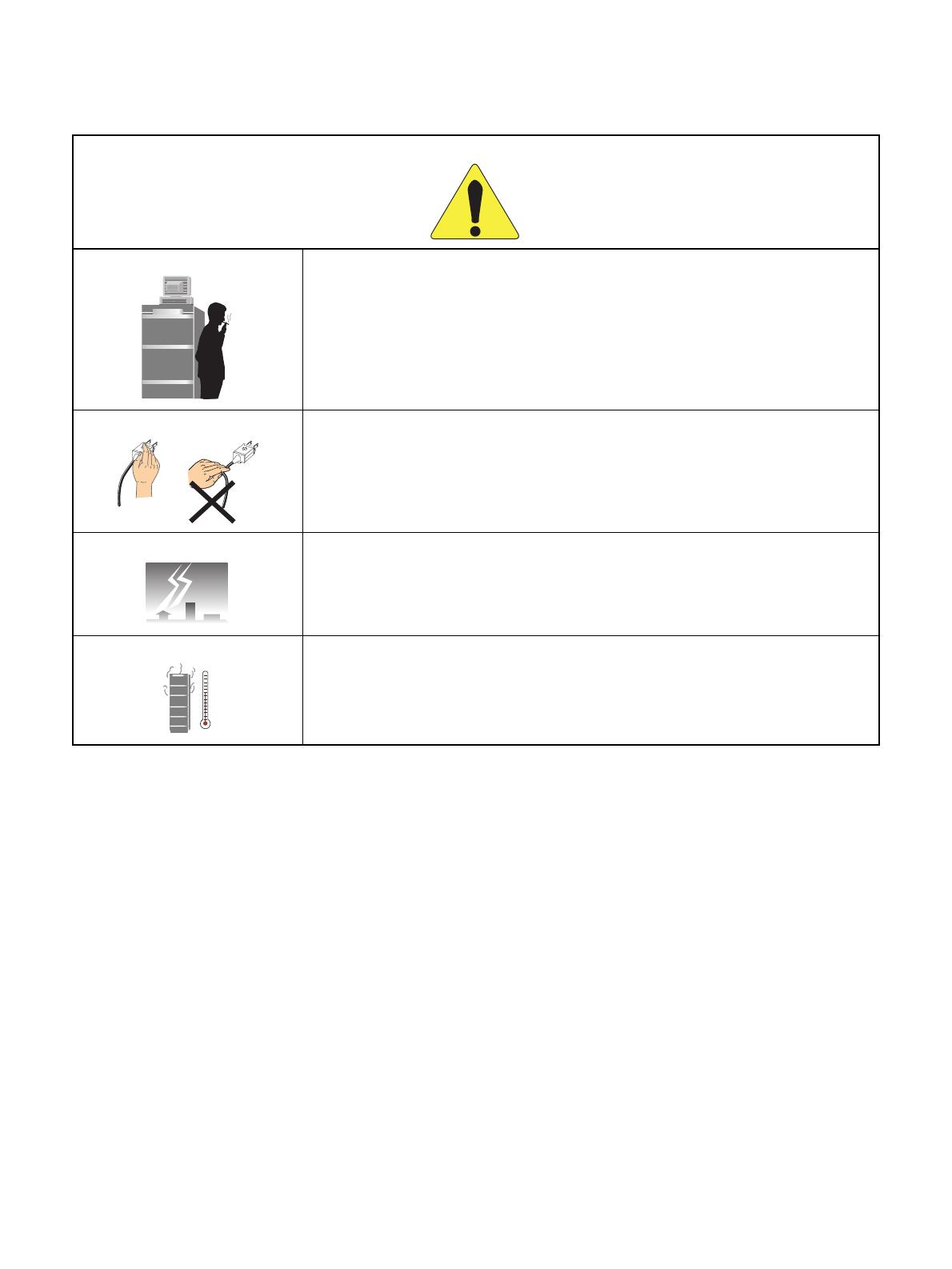
WARNING
Be careful of using a battery as following:
Rechargeable lead battery is used as the emergency battery of PBX. Check the back-
up for an electricity failure.
Battery electrolyte is harmful to human body. If the battery electrolyte is put on the
cloth, clean it using enough amount of water.
Do not cause the battery short intentionally. Do not put it near fire or put it into fire.
Do not damage it, such as disassembly, falling, and impact.
The battery life varies depending on the surroundings. The battery life is approxi-
mately three years. If the battery is used outside with high temperature, the battery
life is shortened to approximately one year.
If not replacing terminal or dead battery, the PBX system will not work in case such as
power failure. Besides it might cause smoking or fire due to leaking battery electrolyte.
Perform the periodic diagnosis surely. Note that the battery is one of periodic replace-
ment parts whose cost are charged to the customer. We recommend you to make a con-
tract with supplier or service technician about the routine maintenance.
Do not touch the peripheral equipment by wet hand. Do not wet the peripheral equip-
ment.
Do not touch the ink head and the internal of the printer. When replacing the ink ribbon
or the paper, make sure it is cool enough.
Do not drop nor impact the peripheral equipment. It might cause a failure.
155 53 13 123
Connection:
Connection:
PWR:
PWR:
Rcv:
Rcv:
Snd:
Snd:
TCP UDP
ENT
ENT
1 2 3
4
5 6
7
8
9
0
#
*
155
155
53
13
123
P
ro
t
o
c
o
l
:
Protocol:
T
CP
TCP
Co
nne
ctio
n:
Connection:
PWR
:
PWR:
Rcv:
Snd
:
Snd:
TCP
TCP
UDP
E
N
T
ENT
1
2
3
4
5
6
7
8
9
0
#
*
PRODUCT LIABILITY ND-71762 (E)
PL- 6
Issue 2
PRODUCT LIABILITY
2.2 Notice Regarding Lightenning Strikes
ATTENTION
Do not use benzine, thinner, and alcohol for cleaning. When it is difficult to clean dust
and dirt, put weaken neutral detergent onto a cloth, and give the cloth a wiring. Clean
dust and dirt with the cloth, and rub them with a dry cloth.
Do not place equipment in the following:
Locations which receive direct sunlight
Locations where the moisture exceeds the allowed level
Locations which might be wet with water, oil, and chemicals
Locations which is particularly low in temperature (such as an ice compartment)
Locations which receive the electric wave or the magnetism from TV and (two-way)
radio
Locations which receive the illegal electric wave
Note that the life of PBX and Main Power is shorten if placed in the location affected
by much of hydrogen sulfide or salt, such as seaside area.
WARNING
It is necessary to take proper procedures to avoid damage to the PBX caused by local lightening strikes
and other electrical surges.
As for grounding conductors, there needs to be two-type grounding conductors; one is below 10
Ω
(Type 1) and the other is below 100
Ω (Type 2). In particular, the Type 1 is used for the electronics
circuit installment, therefore, it must be used as isolated system to keep from electricity difference
caused by lightening strikes.
The Type 1 is used when connecting the FE of PBX, the PE of Main Power, MDF, etc.
Extract the ground terminal (grounding electrode of three terminals) from the earth board same with
that of the main equipment. The ground terminal attached with AC100V plug outlet is used for MAT,
printer, MODEM, and measurement machine for maintenance.
Thinner

ND-71762 (E) PRODUCT LIABILITY
PL- 7
Issue 2
PRODUCT LIABILITY
2.3 Periodic Repair Parts and Disposables
ATTENTION
Replace the periodic repair parts such as fan, battery, backup battery, HD, fuse, and display. If not
change the parts and past the periodic term, sudden traffic fault might lead to the whole system failure
and damaging. Replace the disposables such as ink ribbon, FD, recording paper, and headset.
We recommend you to make a contract for the maintenance service.

PRODUCT LIABILITY ND-71762 (E)
PL- 8
Issue 2
This page is for your notes.

ND-71762 (E)
ISSUE 2
AUGUST, 2002
NEAX2400 IPX
Internet Protocol eXchange
No.7 CCIS System Manual
TABLE OF CONTENTS
Page
ND-71762 (E) TABLE OF CONTENTS
Page i
Issue 2
CHAPTER 1 INTRODUCTION . . . . . . . . . . . . . . . . . . . . . . . . . . . . . . . . . . . . . . . . . . . . . . . . . . . . . . . . . . 1
1.GENERAL . . . . . . . . . . . . . . . . . . . . . . . . . . . . . . . . . . . . . . . . . . . . . . . . . . . . . . . . . . . . . . . . . . . . . . . . 1
2.HOW TO FOLLOW THE MANUAL . . . . . . . . . . . . . . . . . . . . . . . . . . . . . . . . . . . . . . . . . . . . . . . . . . . . . 1
2.1 Configuration of the No. 7 CCIS System Manual . . . . . . . . . . . . . . . . . . . . . . . . . . . . . . . . . . . . 1
CHAPTER 2 GENERAL INFORMATION FOR CCIS . . . . . . . . . . . . . . . . . . . . . . . . . . . . . . . . . . . . . . . . . 2
1.GENERAL . . . . . . . . . . . . . . . . . . . . . . . . . . . . . . . . . . . . . . . . . . . . . . . . . . . . . . . . . . . . . . . . . . . . . . . . 2
2.DESCRIPTION OF CCIS . . . . . . . . . . . . . . . . . . . . . . . . . . . . . . . . . . . . . . . . . . . . . . . . . . . . . . . . . . . . 2
3.SYSTEM CONFIGURATION . . . . . . . . . . . . . . . . . . . . . . . . . . . . . . . . . . . . . . . . . . . . . . . . . . . . . . . . . . 4
3.1 Outline . . . . . . . . . . . . . . . . . . . . . . . . . . . . . . . . . . . . . . . . . . . . . . . . . . . . . . . . . . . . . . . . . . . . . 4
4.NETWORK CONFIGURATION . . . . . . . . . . . . . . . . . . . . . . . . . . . . . . . . . . . . . . . . . . . . . . . . . . . . . . . . 6
4.1 Types of Network . . . . . . . . . . . . . . . . . . . . . . . . . . . . . . . . . . . . . . . . . . . . . . . . . . . . . . . . . . . . . 8
4.2 Examples of Network Configuration . . . . . . . . . . . . . . . . . . . . . . . . . . . . . . . . . . . . . . . . . . . . . . 9
4.2.1 Main-Satellite Configuration . . . . . . . . . . . . . . . . . . . . . . . . . . . . . . . . . . . . . . . . . . . . . . .9
4.2.2 Campus Configuration . . . . . . . . . . . . . . . . . . . . . . . . . . . . . . . . . . . . . . . . . . . . . . . . . . .10
4.2.3 Main-Remote Configuration . . . . . . . . . . . . . . . . . . . . . . . . . . . . . . . . . . . . . . . . . . . . . . . 11
4.3 CCIS Network Modes . . . . . . . . . . . . . . . . . . . . . . . . . . . . . . . . . . . . . . . . . . . . . . . . . . . . . . . . . 12
4.3.1 Associated Mode . . . . . . . . . . . . . . . . . . . . . . . . . . . . . . . . . . . . . . . . . . . . . . . . . . . . . . . 12
4.3.2 Quasi-Associated Mode . . . . . . . . . . . . . . . . . . . . . . . . . . . . . . . . . . . . . . . . . . . . . . . . . .13
4.4 CCIS Network Redundancy . . . . . . . . . . . . . . . . . . . . . . . . . . . . . . . . . . . . . . . . . . . . . . . . . . . . 13
5.DIGITAL NETWORK AND NETWORK SYNCHRONIZATION . . . . . . . . . . . . . . . . . . . . . . . . . . . . . . . . 14
5.1 Outline . . . . . . . . . . . . . . . . . . . . . . . . . . . . . . . . . . . . . . . . . . . . . . . . . . . . . . . . . . . . . . . . . . . . . 14
5.2 Office Rank . . . . . . . . . . . . . . . . . . . . . . . . . . . . . . . . . . . . . . . . . . . . . . . . . . . . . . . . . . . . . . . . . 16
5.2.1 Source Office . . . . . . . . . . . . . . . . . . . . . . . . . . . . . . . . . . . . . . . . . . . . . . . . . . . . . . . . . . 16
5.2.2 Sub-Source Office . . . . . . . . . . . . . . . . . . . . . . . . . . . . . . . . . . . . . . . . . . . . . . . . . . . . . . . 17
5.2.3 Receiver Office and Local Receiver Office . . . . . . . . . . . . . . . . . . . . . . . . . . . . . . . . . . . . 18
5.3 Clock Pulses from M-OSC/EXT. OSC and Connection with PLO/OSC . . . . . . . . . . . . . . . . . . . 19
5.4 Clocks Extracted from DTI and Connection of PLO/TSW . . . . . . . . . . . . . . . . . . . . . . . . . . . . . . 20
5.5 Automatic Clock Route Changeover . . . . . . . . . . . . . . . . . . . . . . . . . . . . . . . . . . . . . . . . . . . . . .22
5.5.1 Automatic Route Changeover on Fault to M-OSC/EXT. OSC of Input Clock Route . . . . 22
5.5.2 Automatic Route Changeover on Fault to DTI of Input Clock Route . . . . . . . . . . . . . . . . 22
6.NETWORK THROUGH FCCS GROUPS AND NEAX2000 IPS Internet Protocol Server . . . . . . . . . . . 25
6.1 Network Configuration . . . . . . . . . . . . . . . . . . . . . . . . . . . . . . . . . . . . . . . . . . . . . . . . . . . . . . . . . 25
6.2 Conditions for Network Establishment . . . . . . . . . . . . . . . . . . . . . . . . . . . . . . . . . . . . . . . . . . . .26
6.3 FCCS Group (FUG) . . . . . . . . . . . . . . . . . . . . . . . . . . . . . . . . . . . . . . . . . . . . . . . . . . . . . . . . . . . 27
6.4 Interactions . . . . . . . . . . . . . . . . . . . . . . . . . . . . . . . . . . . . . . . . . . . . . . . . . . . . . . . . . . . . . . . . . 28
CHAPTER 3 SWITCH SETTING SHEETS . . . . . . . . . . . . . . . . . . . . . . . . . . . . . . . . . . . . . . . . . . . . . . . . . 29
1.GENERAL . . . . . . . . . . . . . . . . . . . . . . . . . . . . . . . . . . . . . . . . . . . . . . . . . . . . . . . . . . . . . . . . . . . . . . . . 29
2.LIST OF CIRCUIT CARDS . . . . . . . . . . . . . . . . . . . . . . . . . . . . . . . . . . . . . . . . . . . . . . . . . . . . . . . . . . . 29

TABLE OF CONTENTS ND-71762 (E)
Page ii
Issue 2
TABLE OF CONTENTS (CONTINUED)
Page
CHAPTER 4 INSTALLATION PROCEDURE . . . . . . . . . . . . . . . . . . . . . . . . . . . . . . . . . . . . . . . . . . . . . . . 30
1.GENERAL . . . . . . . . . . . . . . . . . . . . . . . . . . . . . . . . . . . . . . . . . . . . . . . . . . . . . . . . . . . . . . . . . . . . . . . . 30
2.PRECAUTIONS ON INSTALLATION . . . . . . . . . . . . . . . . . . . . . . . . . . . . . . . . . . . . . . . . . . . . . . . . . . . 30
3.INSTALLATION PROCEDURE . . . . . . . . . . . . . . . . . . . . . . . . . . . . . . . . . . . . . . . . . . . . . . . . . . . . . . . . 32
3.1 General Flow of Installation Procedure . . . . . . . . . . . . . . . . . . . . . . . . . . . . . . . . . . . . . . . . . . . . 32
3.2 Setting of Switch Positions and Mounting of the Circuit Cards . . . . . . . . . . . . . . . . . . . . . . . . . . 33
3.3 Cable Termination and Cross Connection from the MDF to the DSU . . . . . . . . . . . . . . . . . . . . . 35
3.4 Front Cable Connection between DTI and CCH . . . . . . . . . . . . . . . . . . . . . . . . . . . . . . . . . . . . . 43
3.5 Cable Running from PBX to the MODEM for Analog CCIS Line . . . . . . . . . . . . . . . . . . . . . . . . . 44
CHAPTER 5 INSTALLATION TEST PROCEDURE . . . . . . . . . . . . . . . . . . . . . . . . . . . . . . . . . . . . . . . . . . 49
1.GENERAL . . . . . . . . . . . . . . . . . . . . . . . . . . . . . . . . . . . . . . . . . . . . . . . . . . . . . . . . . . . . . . . . . . . . . . . . 49
2.INSTALLATION TEST PROCEDURE . . . . . . . . . . . . . . . . . . . . . . . . . . . . . . . . . . . . . . . . . . . . . . . . . . . 49
2.1 Overall Test for CCIS Line . . . . . . . . . . . . . . . . . . . . . . . . . . . . . . . . . . . . . . . . . . . . . . . . . . . . . . 49
2.1.1 Overall Test of CCIS Tie Line Outgoing Call . . . . . . . . . . . . . . . . . . . . . . . . . . . . . . . . . . 50
2.1.2 Overall Test of CCIS Tie Line Incoming Call . . . . . . . . . . . . . . . . . . . . . . . . . . . . . . . . . . 52
2.1.3 Test of Connection and Alternate Routing to All Tie Lines . . . . . . . . . . . . . . . . . . . . . . . . 53
2.1.4 Test of Tandem Connection to Tie Line . . . . . . . . . . . . . . . . . . . . . . . . . . . . . . . . . . . . . . 55
2.1.5 PAD Setting . . . . . . . . . . . . . . . . . . . . . . . . . . . . . . . . . . . . . . . . . . . . . . . . . . . . . . . . . . . 57
2.2 CCIS Service Feature Functional Test . . . . . . . . . . . . . . . . . . . . . . . . . . . . . . . . . . . . . . . . . . . .58
2.2.1 Test of Interoffice Station to Station Connection . . . . . . . . . . . . . . . . . . . . . . . . . . . . . . . . 59
2.2.2 Test of Outgoing Call Connection to Tie Line Trunk . . . . . . . . . . . . . . . . . . . . . . . . . . . . . 60
2.2.3 Test of Transfer Services . . . . . . . . . . . . . . . . . . . . . . . . . . . . . . . . . . . . . . . . . . . . . . . . . 61
2.2.4 Test of Services from ATTCON . . . . . . . . . . . . . . . . . . . . . . . . . . . . . . . . . . . . . . . . . . . . 62
2.2.5 Test of other Services . . . . . . . . . . . . . . . . . . . . . . . . . . . . . . . . . . . . . . . . . . . . . . . . . . . . 63
3.TEST RESULT REPORT . . . . . . . . . . . . . . . . . . . . . . . . . . . . . . . . . . . . . . . . . . . . . . . . . . . . . . . . . . . . 64
3.1 CCIS Service Feature Functional Test . . . . . . . . . . . . . . . . . . . . . . . . . . . . . . . . . . . . . . . . . . . .64
3.1.1 Test of Interoffice Station to Station Connection . . . . . . . . . . . . . . . . . . . . . . . . . . . . . . . . 64
3.1.2 Test of Outgoing Call Connection to Tie Line Trunk . . . . . . . . . . . . . . . . . . . . . . . . . . . . . 64
3.1.3 Test of Transfer Services . . . . . . . . . . . . . . . . . . . . . . . . . . . . . . . . . . . . . . . . . . . . . . . . . 64
3.1.4 Test of Services from ATTCON . . . . . . . . . . . . . . . . . . . . . . . . . . . . . . . . . . . . . . . . . . . . 65
3.1.5 Test of Other Services . . . . . . . . . . . . . . . . . . . . . . . . . . . . . . . . . . . . . . . . . . . . . . . . . . . 65
CHAPTER 6 BASIC DATA ASSIGNMENT . . . . . . . . . . . . . . . . . . . . . . . . . . . . . . . . . . . . . . . . . . . . . . . . . 66
1.GENERAL . . . . . . . . . . . . . . . . . . . . . . . . . . . . . . . . . . . . . . . . . . . . . . . . . . . . . . . . . . . . . . . . . . . . . . . . 66
2.DATA ASSIGNMENT . . . . . . . . . . . . . . . . . . . . . . . . . . . . . . . . . . . . . . . . . . . . . . . . . . . . . . . . . . . . . . . 67
2.1 Port Allocation and Related Command . . . . . . . . . . . . . . . . . . . . . . . . . . . . . . . . . . . . . . . . . . . . 67
2.2 Basic Data Assignment Procedure . . . . . . . . . . . . . . . . . . . . . . . . . . . . . . . . . . . . . . . . . . . . . . . 68
2.3 FCCS Data Assignment Procedure . . . . . . . . . . . . . . . . . . . . . . . . . . . . . . . . . . . . . . . . . . . . . . .76
CHAPTER 7 CCIS SERVICE FEATURES . . . . . . . . . . . . . . . . . . . . . . . . . . . . . . . . . . . . . . . . . . . . . . . . . 81
1.GENERAL . . . . . . . . . . . . . . . . . . . . . . . . . . . . . . . . . . . . . . . . . . . . . . . . . . . . . . . . . . . . . . . . . . . . . . . . 81
CHAPTER 8 MAINTENANCE PROCEDURE . . . . . . . . . . . . . . . . . . . . . . . . . . . . . . . . . . . . . . . . . . . . . . . 84
1.GENERAL . . . . . . . . . . . . . . . . . . . . . . . . . . . . . . . . . . . . . . . . . . . . . . . . . . . . . . . . . . . . . . . . . . . . . . . . 84
2.SYSTEM MESSAGES . . . . . . . . . . . . . . . . . . . . . . . . . . . . . . . . . . . . . . . . . . . . . . . . . . . . . . . . . . . . . . . 84
2.1 The Relationship between System Messages and Lamp Indications . . . . . . . . . . . . . . . . . . . . . 85

ND-71762 (E) TABLE OF CONTENTS
Page iii
Issue 2
TABLE OF CONTENTS (CONTINUED)
Page
2.2 Technical Terms for Explaining Message Detail Data . . . . . . . . . . . . . . . . . . . . . . . . . . . . . . . . . 86
2.2.1 Circuit Card Mounting Information . . . . . . . . . . . . . . . . . . . . . . . . . . . . . . . . . . . . . . . . . . 87
2.3 How to Proceed with Diagnostic Work from System Message . . . . . . . . . . . . . . . . . . . . . . . . . . 89
2.4 System Messages . . . . . . . . . . . . . . . . . . . . . . . . . . . . . . . . . . . . . . . . . . . . . . . . . . . . . . . . . . . . 91
3.CCIS (Common Channel Interoffice Signaling) Line Fault . . . . . . . . . . . . . . . . . . . . . . . . . . . . . . . . . . . 114
3.1 Check Point . . . . . . . . . . . . . . . . . . . . . . . . . . . . . . . . . . . . . . . . . . . . . . . . . . . . . . . . . . . . . . . . . 114
3.2 CCIS Line Control . . . . . . . . . . . . . . . . . . . . . . . . . . . . . . . . . . . . . . . . . . . . . . . . . . . . . . . . . . . . 114
3.3 Fault Repair Procedure for Digital CCIS Line . . . . . . . . . . . . . . . . . . . . . . . . . . . . . . . . . . . . . . . 115
3.4 Fault Repair Procedure for Analog CCIS Line . . . . . . . . . . . . . . . . . . . . . . . . . . . . . . . . . . . . . . 116
4.CCIS LINE OPERATING MODE CONTROL . . . . . . . . . . . . . . . . . . . . . . . . . . . . . . . . . . . . . . . . . . . . . 118
5.INSERTION/EXTRACTION OF CIRCUIT CARDS . . . . . . . . . . . . . . . . . . . . . . . . . . . . . . . . . . . . . . . . . 119
5.1 CCH Circuit Card . . . . . . . . . . . . . . . . . . . . . . . . . . . . . . . . . . . . . . . . . . . . . . . . . . . . . . . . . . . . . 119
5.2 DTI Circuit Card . . . . . . . . . . . . . . . . . . . . . . . . . . . . . . . . . . . . . . . . . . . . . . . . . . . . . . . . . . . . . . 120
5.3 CCT Circuit Card . . . . . . . . . . . . . . . . . . . . . . . . . . . . . . . . . . . . . . . . . . . . . . . . . . . . . . . . . . . . . 121
5.4 PLO/OSC Circuit Card . . . . . . . . . . . . . . . . . . . . . . . . . . . . . . . . . . . . . . . . . . . . . . . . . . . . . . . . 122

TABLE OF CONTENTS ND-71762 (E)
Page iv
Issue 2
This page is for your notes.

ND-71762 (E) CHAPTER 1
Page 1
Issue 2
INTRODUCTION
CHAPTER 1 INTRODUCTION
1. GENERAL
This manual describes the installation procedures, maintenance, etc. for connecting No. 7 CCIS (Common Channel
Interoffice Signaling) lines to the PBX.
The configuration of this manual is described in Section 2: “HOW TO FOLLOW THE MANUAL” of this chapter.
2. HOW TO FOLLOW THE MANUAL
2.1 Configuration of the No. 7 CCIS System Manual
Note: Because the system name varies depending on the country to be provided, each system is described as fol-
lows in this manual.
Table 1-1 Configuration of the No. 7 CCIS System Manual
CHAPTER TITLE DESCRIPTION
1 INTRODUCTION Describes the No. 7 CCIS System Manual and how to use it.
2
GENERAL INFORMATION FOR
CCIS
Describes the specification and configuration of the PBX.
3 SWITCH SETTING SHEETS Describes the switch setting for each circuit card.
4 INSTALLATION PROCEDURE Describes how to connect CCIS lines to the PBX.
5
INSTALLATION TEST
PROCEDURE
Describes the PBX installation test procedure for CCIS.
6 BASIC DATA ASSIGNMENT Describes the basic data assignment for establishing CCIS link.
7
CCIS SERVICE FEATURES Describes the functions, operating procedure, and office data as-
signment procedure for each CCIS service feature.
8 MAINTENANCE PROCEDURE Describes the PBX maintenance procedure for CCIS.

CHAPTER 2 ND-71762 (E)
Page 2
Issue 2
GENERAL INFORMATION FOR CCIS
CHAPTER 2 GENERAL INFORMATION FOR CCIS
1. GENERAL
This chapter describes the functional outline of CCIS, hardware required for CCIS, and service features which can
be provided by CCIS.
2. DESCRIPTION OF CCIS
The modular architecture and wide range of voice and data features available with the digital PBX’s have been de-
veloped with emphasis on continued enhancement within a single PBX. In order to meet the growing demand for
further enhancement on a network level, NEC developed a networking system employing Common Channel Inter-
office Signaling (CCIS). The CCIS system links together individual PBX systems (nodes) to form a transparent
voice and data network which acts as a single large PBX, even though terminals within the network are, in fact, con-
nected to different PBX’s. Common Channel Interoffice Signaling (CCIS) derives its name from the fact that a sig-
naling channel (link), separate from voice and data channels, is provided between nodes for the sole purpose of
signal exchange. This signaling link is used in common by all voice and data links for exchange of information re-
lating to addressing (e.g. dialed digits, calling/called number); supervisory functions (e.g. call setup and termina-
tion); and network accounting and management (e.g. centralized billing and fault reporting.) This is unlike
conventional tie line networks which exchange signaling information over the same links as are for voice transmis-
sion (Associated Channel Interoffice Signaling.)
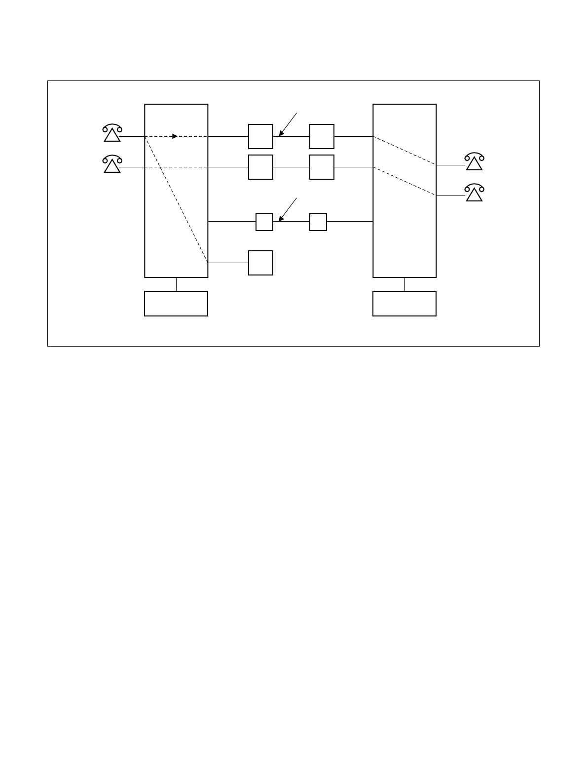
The block diagrams in Figure 2-1 and 2-2 illustrate the difference between Common Channel Interoffice Signalling
(CCIS) and Associated Channel (In-band) Interoffice Signaling (ACIS).
Figure 2-1 Associated Channel (In-Band) Interoffice Signaling
SIGNALING AND VOICE VIA THE SAME LINK
SND REG REG
CONTROL CONTROL
TRUNK TRUNK
ND-71762 (E) CHAPTER 2
Page 3
Issue 2
GENERAL INFORMATION FOR CCIS
Figure 2-2 Common Channel Interoffice Signaling
Some advantages of the separate signaling link provided by CCIS are:
(a) Network Transparency
Because CCIS allows data relating to service features and station/trunk status to be exchanged between nodes
at a high rate of speed (64 Kbps), service is provided to all users as though the CCIS network was a single PBX.
(b) Centralized Facilities
Centralized Management: Fault messages from all nodes can be directed to one centralized (management)
node.
Centralized Billing: Billing information for all nodes in the network can be processed at one central
location.
Centralized Attendant Service: It is not necessary in a CCIS network to have an Attendant Console at each
node in the network. Attendant services can be provided to multiple nodes from
one or more central location(s).
(c) Better Utilization of Trunking Facilities
Because network signaling is carried over separate signaling links, more efficient use can be made for network
trunks (reduced call holding time, reduced connection time, etc.). In another word, the number of trunk cir-
cuits, which required to provide a specified traffic capacity, can be reduced.
COMMUNICATION LINK
REG
CONTROL CONTROL
SIGNALING LINK

CHAPTER 2 ND-71762 (E)
Page 4
Issue 2
GENERAL INFORMATION FOR CCIS
(d) Network Reliability
Alternate Routing provides the CCIS network with maximum reliability. If the signaling link between two
nodes should fail, signaling is sent over an alternate route, via another node, without loss of service. Directly-
connected redundant links can also be provided to assure the reliability of the network.
(e) Reduction in Personnel
Because management, cost accounting, and services, such as Attendant operation, can be centralized, the num-
ber of people necessary to administer the network can be reduced.
(f) Reduced Hardware
Signaling over a common channel; better utilization of trunking facilities; and centralized management and
services all result in a vast reduction in hardware when a CCIS network, rather than a conventional Tie line
network, is used.
3. SYSTEM CONFIGURATION
3.1 Outline
This Section describes the hardware configuration and its specification, the names of interface equipment and other
related subjects. Figure 2-3 shows No. 7 hardware configuration, respectively. The control signal circuit used for
CCIS is classified into the digital circuit and analog circuit. The CCH card can be used for both digital and analog
control signal circuit and the CCT card is used for digital one. CCH sends control signals to and receives from the
distant office. Also, for network synchronization, PLO/OSC or TSW (Phase Lock Oscillator/Oscillator or Time Di-
vision Switch) are used.
For the analog control signal circuit, CCH circuit card is used with MODEM.
Table 2-1 shows the CCIS interface specifications and their applications.
Table 2-1 CCIS Interface Specifications
TYPE OF
FACILITY
SIGNALING
RATE
INTERFACE
SPECIFICATION
INTERFACE
EQUIPMENT
APPLICATION
Voice Frequency
Circuit
4.8 kbps RS-232C, V. 24, V.
28
MODEM V27
or equivalent
Used for a CCIS Tie Line (4ODT) Net-
work.
1.544 Mbps 48-64 kbps T1-D3 T1 Channel Used with T1 (24DTI) lines.
2.048 Mbps 64 kbps E1 E1 Channel Used with E1 (30 DTI) lines.
AT&T IS DDS 56 kbps V. 35,
V. 28/V.11
NEC DCP DSU
or equivalent
Used if network has extensive Tie Lines,
with heavy traffic conditions, and AT&T
IS Digital Data Service is available.

ND-71762 (E) CHAPTER 2
Page 5
Issue 2
GENERAL INFORMATION FOR CCIS
Figure 2-3 Hardware Configuration of No. 7 CCIS System
MDF
<CCIS Digital Line>
<CCIS Analog Line>
CCT
Note 1
Note 1
Note 2
No.7 CCIS
Speech Line
and Signalling
Line
No.7 CCIS
Speech Line
No.7 CCIS
Signalling
Line
DTI
CCH
TRK
TRK
CCHMODEM
Speech
Path
System
PLO
CPU
Note 1: When using one channel of the DTI as the Control Link.
Note 2: When using Analog MODEM as the Control Link.

CHAPTER 2 ND-71762 (E)
Page 6
Issue 2
GENERAL INFORMATION FOR CCIS
4. NETWORK CONFIGURATION
With application of No. 7 CCIS added to the PBX, a network of multiple functions as if it were a single PBX.
Since calls can be freely transferred between one PBX and another, most of the existing station services can be ap-
plied to inter-PBX call connections.
Further, using the CENTRALIZED BILLING-CCIS service and the CENTRALIZED SYSTEM MANAGEMENT
REPORT-CCIS service, billing information and fault information can be processed at one center point instead of
processing at each PBX concerned.
Figure 2-4 shows an example of PBX interoffice network for CCIS Digital Line, and Figure 2-5 shows an example
of network configuration for CCIS Analog Line.
Figure 2-4 Example of Network Configuration for CCIS Digital Line
LC
LC
ATI
PBX
DTI
CCH
CCT
COT C.O
LC
LC
ATI
PBX
DTI
CCH
DTI
CCH
CCT
COT
DTI
CCH
C.O
PBXPBX
LC
LC
ATI
DTI
CCH
CCT
COT
C.O
LC
LC
ATI
DTI
CCH
CCT
COT
C.O
Failure, charging information
One channel of DTI shall be used for signals.
indicates a speech line.
indicates a signal line.
/