4
USING THE UNIT SAFELY
002c
• Do not open (or modify in any way) the unit or
its AC adaptor.
.......................................................................................................................
003
• Do not attempt to repair the unit, or replace
parts within it (except when this manual
provides specific instructions directing you to
do so). Refer all servicing to your retailer, the
nearest Roland Service Center, or an autho-
rized Roland distributor, as listed on the “Infor-
mation” sheet.
.......................................................................................................................
004
• Never install the unit in any of the following
locations.
• Subject to temperature extremes (e.g.,
direct sunlight in an enclosed vehicle, near
a heating duct, on top of heat-generating
equipment); or are
• Damp (e.g., baths, washrooms, on wet
floors); or are
• Exposed to steam or smoke; or are
• Subject to salt exposure; or are
• Humid; or are
• Exposed to rain; or are
• Dusty or sandy; or are
• Subject to high levels of vibration and
shakiness.
.......................................................................................................................
007
• Make sure you always have the unit placed so it
is level and sure to remain stable. Never place it
on stands that could wobble, or on inclined
surfaces.
.......................................................................................................................
008c
• Be sure to use only the AC adaptor supplied
with the unit. Also, make sure the line voltage
at the installation matches the input voltage
specified on the AC adaptor’s body. Other AC
adaptors may use a different polarity, or be
designed for a different voltage, so their use
could result in damage, malfunction, or electric
shock.
.......................................................................................................................
008e
• Use only the attached power-supply cord. Also,
the supplied power cord must not be used
with any other device.
.......................................................................................................................
009
• Do not excessively twist or bend the power
cord, nor place heavy objects on it. Doing so
can damage the cord, producing severed
elements and short circuits. Damaged cords
are fire and shock hazards!
.......................................................................................................................
010
• In combination with an amplifier and
headphones or speakers, this unit may be
capable of producing sound levels that could
cause permanent hearing loss. Do not operate
for a long period of time at a high volume level,
or at a level that is uncomfortable. If you
experience any hearing loss or ringing in the
ears, you should immediately stop using the
unit, and consult an audiologist.
.......................................................................................................................
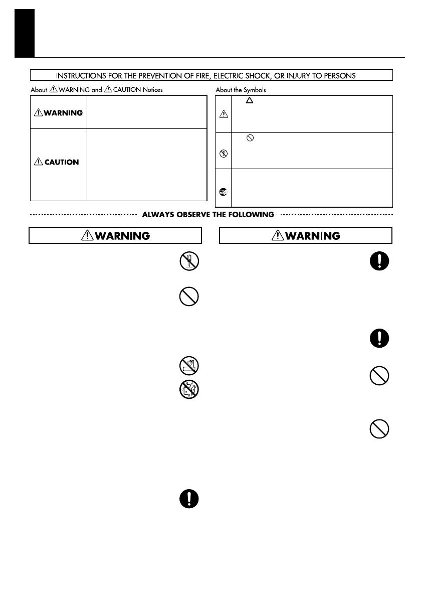
Used for instructions intended to alert
the user to the risk of injury or material
damage should the unit be used
improperly.
* Material damage refers to damage or
other adverse effects caused with
respect to the home and all its
furnishings, as well to domestic
animals or pets.
Used for instructions intended to alert
the user to the risk of death or severe
injury should the unit be used
improperly.
The ● symbol alerts the user to things that must be
carried out. The specific thing that must be done is
indicated by the design contained within the circle. In
the case of the symbol at left, it means that the power-
cord plug must be unplugged from the outlet.
The symbol alerts the user to important instructions
or warnings.The specific meaning of the symbol is
determined by the design contained within the
triangle. In the case of the symbol at left, it is used for
The symbol alerts the user to items that must never
be carried out (are forbidden). The specific thing that
must not be done is indicated by the design contained
within the circle. In the case of the symbol at left, it
means that the unit must never be disassembled.


