Page is loading ...

CR, CRI, CRN
Double shaft seal (tandem)
Service instructions
GRUNDFOS INSTRUCTIONS

English (GB)
2
English (GB) Service instructions
Original service instructions.
CONTENTS
Page
1. Symbols used in this document
2. General information
Position numbers of parts (digits) refer to drawings and parts
lists; position numbers of tools (letters) refer to section 5. Service
tools.
Electrical parts must only be serviced by Grundfos or an
authorised service workshop.
Before dismantling
• Close the isolating valves, if fitted, and make sure that they
cannot be accidentally opened.
• Before starting work on the product, let the product and
pumped liquid cool off.
Before assembly
• Clean and check all parts.
• Replace defective parts with new parts.
• Order the necessary service kits.
• Always replace gaskets and O-rings.
During assembly
• Tighten screws and nuts according to section 3. Torques.
• Lubricate rings and screws according to section 4. Lubricants.
After assembly
If analog or digital inputs, the relay output or the CIM module has
been removed from the pump, you must check the
communication with external units after service.
1. Symbols used in this document
2
2. General information
2
3. Torques
3
4. Lubricants
3
5. Service tools
4
6. CR, CRI, CRN 1, 3, 5
5
6.1 Dismantling
5
6.2 Assembly
5
7. CR, CRI, CRN 10, 15, 20
6
7.1 Dismantling
6
7.2 Assembly
6
8. CR, CRI, CRN 32, 45, 64, 90
7
8.1 Dismantling
7
8.2 Assembly
7
9. CR, CRN 120, 150
8
9.1 Dismantling
8
9.2 Assembly
8
10. Exploded views
10
Warning
Prior to service work, read these service
instructions carefully. Installation and service
work must comply with local regulations and
accepted codes of good practice.
Observe the safety instructions in the installation
and operating instructions for the product.
Warning
If these safety instructions are not observed,
it may result in personal injury.
Warning
If these instructions are not observed, it may lead
to electric shock with consequent risk of serious
personal injury or death.
Caution
If these safety instructions are not observed,
it may result in malfunction or damage to the
equipment.
Note
Notes or instructions that make the job easier
and ensure safe operation.
Warning
Use personal protective equipment if there is a
risk of getting into contact with the pumped
liquid.
Observe local regulations.
Warning
Switch off the power supply and make sure that it
cannot be accidentally switched on.
Check that other pumps or sources do not force
flow through the pump even if the pump is
stopped. This will cause the motor to act like a
generator, resulting in voltage on the pump.

English (GB)
3
3. Torques 4. Lubricants
Pos. Description Pump Dimensions Torque
9
Coupling
screws
CR, CRI, CRN
1, 3, 5, 10, 15,
20
M6 13
M8 31
M10 62
CR, CRN 32,
45, 64, 90
-85
CR, CRN 120,
150
M10 85
M16 100
7a
Coupling
guard
screws
CR, CRN 32,
45, 64, 90,
120, 150
-6
18, 18a,
18b
Air vent
screws
CR, CRI, CRN
1, 3, 5, 10, 15,
20, 32, 45, 64,
90, 120, 150
-35
23, 23a,
23b, 23c
Drain plugs - 35
28
Motor stool
screws
CR, CRI, CRN
1, 3, 5
M10 23
CR, CRI, CRN
1, 3, 5, 10, 15,
20
M6 10
M8 12
3/8" UNC 23
M12 40
1/2" UNC 40
M16 80
CR, CRN 32,
45, 64, 90,
120, 150
-62
36
Pump head
nuts
CR 1, 3, 5 - 40
CRI 1, 3, 5 - 50
CRN 1, 3, 5 - 60
CR, CRI 10,
15, 20
-80
CRN 10, 15,
20
- 100
CR, CRN 32,
45, 64, 90
- 100
CR, CRN 120,
150
- 120
CR, CRN 120,
150 (55-75
kW)
-80
58a,
58b, 58c
Seal carrier
screws
CR, CRN 32,
45, 64, 90,
120, 150
-62
105,
105b
Shaft seal
CR, CRI, CRN
1, 3, 5, 10, 15,
20
-35
113
Shaft seal
screws
CR, CRI, CRN
1, 3, 5, 10, 15,
20
-2,5
CR, CRN 32,
45, 64, 90,
120, 150
-6
Pos. Designation Product No.
9
THREAD-EZE 00SV999728
58a, 58d, 58c
37a, 37b, 37c Rocol Sapphire Aqua-Sil 00RM2924
51
Soapy Water -
105, 105b
109a, 109b
Rocol Sapphire Aqua-Sil 00RM2924
110, 110b

English (GB)
4
5. Service tools
ABC
DEF
GH I
JKL
MNO
Pos. Designation
For
pos.
CR, CRI,
CRN
Tool
size
Product
No
A
Tee
screwdriver
113
1, 3, 5, 10,
15, 20
2.5 -
120, 150 3 SV0153
B
Slot
screwdriver
7a
1, 3, 5, 10,
15, 20
1.4 -
C
Ring/open-
end spanner
18,
18a
23a,
23b
1, 3, 5, 10,
15, 20, 32,
45, 64, 90,
120, 150
24 SV0122
28
1, 3, 5, 10,
15, 20
10
13
19
SV0083
SV0055
SV0054
32, 45, 64,
90, 120, 150
8SV0273
36
1, 3, 5 19 SV0054
10, 15, 20,
32, 45, 64,
90, 120, 150
24 SV0122
D
Rubber
hammer
SV0349
E Punch 105b
32, 45, 64,
90
SV0015
F Hexagon key
9
1, 3, 5, 10,
15, 20
5
6
8
SV0196
SV0032
32, 45, 64,
90
8 SV0032
120, 150
8
10
SV0032
SV0033
113
1, 3, 5, 10,
15, 20
2.5 SV0277
32, 45, 64,
90, 120, 150
3-
28
32, 45, 64,
90, 120, 150
8 SV0032
58a
32, 45, 64,
90, 120, 150
8 SV0032
G
Torque
screwdriver
113,
7a
1, 3, 5, 10,
15, 20, 32,
45, 64, 90,
120, 150
1-6
Nm
SV0435
SV0438
H Hexagon bit
9
1, 3, 5, 10,
15, 20
5
6
8
SV0010
32, 45, 64,
90
8 SV0010
120, 150
8
10
SV0010
113
1, 3, 5, 10,
15, 20
2.5 SV0012
120, 150 3 -
28
32, 45, 64,
90, 120, 150
8 SV0010
I
Torque
wrench
28
1, 3, 5, 10,
15, 20
4-20
Nm
SV0092
9, 18,
23, 28,
36, 58
1, 3, 5, 10,
15, 20, 32,
45, 64, 90,
120, 150
20-100
Nm
SV0269
36 120, 150
40-200
Nm
SV0400
J
Ring insert
tool
18,
18a
23a,
23b
1, 3, 5, 10,
15, 20, 32,
45, 64, 90,
120, 150
24 SV0524
28
1, 3, 5, 10,
15, 20
10
13
19
SV0310
SV0513
SV0519
32, 45, 64,
90, 120, 150
8SV0411
36
1, 3, 5 19 SV0519
10, 15, 20,
32, 45, 64,
90, 120, 150
24 SV0524
K Sliding guide 8 120, 150 -
L
Adjusting
fork
105
10, 15, 20 96483950
32, 45, 64
90, 120, 150
22 985924
120, 150 32 96731316
M Lifting tool 51 120, 150 97536386
N Eye bolt 28b
32, 45, 64
90, 120, 150
ID2779
O
Tabular box
spanner
105,
105b
1, 3, 5, 10,
15, 20
36 SV2007
Pos. Designation
For
pos.
CR, CRI,
CRN
Tool
size
Product
No

English (GB)
5
6. CR, CRI, CRN 1, 3, 5
6.1 Dismantling
1. Remove screws (pos. 7a) and coupling guards (pos. 7).
2. Remove screws (pos. 9), coupling (pos. 8) and shaft pin
(pos. 10a).
3. Remove screws (pos. 28) and the motor.
4. Slacken socket screws (pos. 113) and remove shaft seal
(pos. 105).
5. Remove nuts (pos. 36).
6. CR: Remove motor stool (pos. 2) and O-ring (pos. 37b).
CRI, CRN: Remove motor stool (pos. 2), pump head cover
(pos. 77) and O-ring (pos. 37b).
7. Slacken socket screws (pos. 113) and remove lower shaft seal
(pos. 105b).
8. Remove cover (pos. 77a).
9. Continue dismantling according to the instructions of the
standard CR pump.
6.2 Assembly
1. Fit O-ring (pos. 37a) and rubber springs (pos. 60) in cover
(pos. 77a).
2. Fit cover (pos. 77a) on the outer sleeve.
3. Lubricate shaft (pos. 51). Fit and tighten lower shaft seal (pos.
105b) in cover (77a).
4. Press the shaft home, and tighten the socket screws of lower
shaft seal (pos. 113), using the hole for air vent screw
(pos. 18a).
5. CR: Fit O-ring (pos. 37b) in motor stool (pos. 2) and fit the
stool on the cover.
CRI, CRN: Fit O-ring (pos. 37b) in pump head cover (pos. 77),
and fit the pump head cover and the motor stool on the cover.
6. Fit washer (pos. 66a) and cross-tighten nuts (pos. 36) on the
staybolts.
7. Lubricate shaft (pos. 51). Fit and tighten upper shaft seal
(pos. 105) in motor stool (pos. 2) or pump head cover
(pos. 77).
8. Lift the pump shaft to its highest position, then push it down to
half way of its lowest position, and tighten the socket screws
of the upper and lower shaft seals.
9. Lift the pump shaft, and fit the adjusting fork. See fig. 1.
Fig. 1 Fitting the adjusting fork
10. Fit the motor and tighten screws (pos. 28).
11. Fit shaft pin (pos. 10a) in the shaft, coupling (pos. 8) and
screws (pos. 9). See fig. 2.
Fig. 2 Fitting the coupling
12. Remove the adjusting fork, and place it on the inside of one of
the coupling guards (pos. 7).
13. Check that the pump shaft can rotate freely.
14. Fit coupling guards (pos. 7) and tighten screws (pos. 7a).
Note
Note that air vent screw (pos. 18a) in the cover is
above drain plug (pos. 25) in the bottom plate.
Note
Make sure that air vent screws (pos. 18 and 18a)
are not positioned on the same side of the pump.
TM02 7923 4403TM05 7451 1113

English (GB)
6
7. CR, CRI, CRN 10, 15, 20
7.1 Dismantling
1. Remove screws (pos. 7a) and coupling guards (pos. 7).
2. Remove screws (pos. 9) and the coupling.
3. Remove screws (pos. 28) and the motor.
4. Slacken socket screws (pos. 113), and remove shaft seal
(pos. 105).
5. Remove nuts (pos. 36).
6. CR: Remove motor stool (pos. 2) and O-ring (pos. 37b).
CRI, CRN: Remove motor stool (pos. 2), pump head cover
(pos. 77), and O-ring (pos. 37b).
7. Slacken socket screws (pos. 113) and remove lower shaft seal
(pos. 105b).
8. Remove cover (pos. 77).
9. Remove rubber springs (pos. 60) from underneath the cover.
10. Continue dismantling according to the instructions of the
standard CR pump.
7.2 Assembly
1. Lubricate O-ring (pos. 37a) and fit it into cover (pos. 77a).
2. Fit new rubber springs (pos. 60) underneath cover (pos. 77a)
and fit the cover on the outer sleeve.
3. Lubricate pump shaft (pos. 51). Fit and tighten lower shaft
seal (pos. 105b).
4. Press the shaft home and tighten socket screws (pos. 113) of
lower shaft seal (pos. 105b).
5. CR: Fit O-ring (pos. 37b) in motor stool (pos. 2) and fit the
stool on the cover.
CRI, CRN: Fit O-ring (pos. 37b) in pump head cover (pos. 2),
and fit the pump head cover and the motor stool on the cover.
6. Fit washers (pos. 66a) and cross-tighten nuts (36) on the
staybolts.
7. Lubricate pump shaft (pos. 51). Fit and tighten upper shaft
seal (pos. 105) in stool (pos. 2) or pump head cover (pos. 77).
8. Press the shaft home, and tighten socket screws (pos. 113) of
upper shaft seal (105).
9. Lift the pump shaft, and insert the adjusting fork under the
shaft seal driver. See fig. 3.
Fig. 3 Fitting the adjusting fork
10. Fit the motor and tighten screws (pos. 28).
11. Fit shaft pin (pos. 10a) in the shaft, coupling (pos. 8) and
screws (pos. 9). See fig. 4.
Fig. 4 Fitting the coupling
12. Remove the adjusting fork, and place it on the inside of one of
the coupling guards (pos. 7).
13. Check that the pump shaft can rotate freely.
14. Fit coupling guards (pos. 7) and screws (pos. 7a).
Note
Note that air vent screw (pos. 18a) in the cover is
above drain plug (pos. 25) in the bottom plate.
Note
Make sure that air vent screws (pos. 18 and 18a)
are not positioned on the same side of the pump.
TM02 7923 4403TM05 7451 1113

English (GB)
7
8. CR, CRI, CRN 32, 45, 64, 90
8.1 Dismantling
1. Remove screws (pos. 7a) and coupling guards (pos. 7).
2. Remove screws (pos. 9) and coupling (pos. 8).
3. Attach the lifting device to eyebolts (pos. 28b).
4. Remove screws (pos. 28). Lift and remove the motor and
motor stool (pos. 1a).
5. Remove the flushing pipes.
6. Slacken socket screws (pos. 113) of the upper shaft seal
(pos. 105), and remove seal driver (pos. 112a).
7. Remove screws (pos. 58a).
8. Remove flushing chamber (pos. 77a).
9. Remove O-ring (pos. 109a).
10. Press stationary shaft seal ring (pos. 103) out of flushing
chamber (pos. 77a), and remove O-ring (pos. 102).
11. Remove lower seal driver (pos. 112) with rotating shaft seal
ring (pos. 104), upper seal driver (pos. 111), O-ring (pos. 107),
spring retainer (pos. 106) and spring (pos. 108).
12. Remove O-ring (pos. 110b).
13. Slacken socket screws (pos. 113) and remove lower shaft seal
(pos. 105b).
14. Continue dismantling according to the instructions of the
standard CR pump.
8.2 Assembly
1. Lubricate the shaft and fit lower shaft seal (pos. 105b).
2. Press the shaft home and tighten sockets screws (pos. 113) of
the lower shaft seal.
3. Lubricate and fit O-ring (pos. 110b) underneath lower seal
driver (pos.112).
4. Fit spring (pos. 108) and spring retainer (pos. 108) on the
lower seal driver.
5. Lubricate and fit O-ring (pos. 107) underneath upper seal
driver (pos. 111).
6. Fit the upper seal driver on the spring retainer.
7. Fit rotating seal ring (pos. 104) on the upper seal driver.
8. Lubricate and fit O-ring (pos. 102) into the stationary seal ring.
9. Fit the stationary seal ring into flushing chamber (pos. 77a).
10. Fit the lower seal driver into flushing chamber (pos. 77a);
make sure that the lower seal driver emerges from the top of
the chamber and that the lower and upper seal drivers
engage.
11. Fit seal driver ring (pos. 112a) on top of the chamber and on
the lower seal driver. Position it so that socket screws
(pos. 113) are aligned with the holes of the lower seal driver.
12. Tighten the socket screws slightly so that they fit into the
holes of the lower seal driver, but still leave room for the shaft
to slide.
Fig. 5 Fitting the upper shaft seal and flushing chamber
13. Fit the adjusting fork between the top of the flushing chamber
and the seal driver ring.
14. Lubricate and fit O-ring (pos. 109a) underneath flushing
chamber (pos. 77a).
15. Fit the flushing chamber on the shaft and press it home on the
pump head.
16. Fit and cross-tighten screws (pos. 58a).
17. Press the pump shaft home and tighten the socket screws
(pos. 113) of the upper shaft seal.
18. Attach the lifting device to the eyebolts. Carefully lift the motor
with the motor stool and fit it on upper pump head (pos. 2a).
Cross-tighten screws (pos. 28).
19. Fit coupling (pos. 8) and tighten screws (pos. 9). See fig. 6.
Fig. 6 Adjusting the coupling
20. Remove the adjusting fork and check that the pump can rotate
freely.
21. Fit coupling guards (pos. 7) and tighten screws (pos. 7a).
Caution
To prevent the motor from tipping over, hold it
straight when using a lifting device.
Note
Note that the shaft seal is spring-loaded.
Note
The extruded part of the spring retainer goes
against the spring.
Caution
Do not touch the seal faces with the fingers or
any greasy tool.
Make sure that the polished face of the rotating
seal ring faces upwards.
TM058746_2613
Caution
To prevent the motor from tipping over, hold it
straight when using a lifting device.
Note
Leave a gap of 2 mm between the bottom of the
coupling and the top of the flushing chamber.
TM03 9607 4207

English (GB)
8
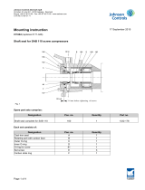
9. CR, CRN 120, 150
9.1 Dismantling
1. Remove screws (pos. 7a) and coupling guards (pos. 7).
2. Remove screws (pos. 9) and coupling (pos. 8).
3. Attach the lifting device to eyebolt (pos. 28b).
4. Remove hexagon socket screws (pos. 28).
5. 55-75 kW: Remove washers (pos. 66a) and nuts (pos. 36)
from the motor stool.
6. Lift and remove motor and motor stool (pos. 1a).
7. Remove screws (pos. 58a).
8. 11-45 kW: Remove seal carrier (pos. 58).
9. Clean shaft (pos. 51) and slacken socket screws (pos. 113) of
upper shaft seal (pos. 105a).
10. Pull shaft seal (pos. 105a) off pump head (pos. 2) and free of
shaft (pos. 51) using two screwdrivers. See fig. 7.
Fig. 7 Removing the upper shaft seal
11. Remove nuts (pos. 36) and washer (pos. 66a) from upper
pump head (pos. 2).
12. Remove upper pump head (pos. 2), it may be necessary to
loosen it with a rubber mallet.
13. Clean the shaft above lower shaft seal (pos. 105b).
14. Loosen socket screw (pos. 113) of lower shaft seal
(pos. 105b).
15. 11-45 kW: Remove screws (pos. 58c)
16. Remove seal carrier (pos. 58b).
17. Pull shaft seal (pos. 105b) off lower pump head (pos. 2b) and
free of shaft (pos. 51) using two screwdrivers.
18. Continue the dismantling according to the instructions for
dismantling of the standard pump.
9.2 Assembly
1. Clean and smooth shaft (pos. 51) using the holder with emery
cloth supplied with the shaft seal kit.
2. Fit lower pump head (pos. 2b) on shaft (pos. 51) and carefully
press it down on the shaft. When it reaches the outer sleeve
press it with even force on the sleeve.
3. Press lower shaft seal (pos. 105b) down into position in lower
pump head (pos. 2b).
4. 11-45 kW: Fit seal carrier (pos. 58b).
5. Cross-tighten screws (pos. 58c).
6. Fit O-ring (pos. 37b) in lower pump head (pos. 2b).
7. Fit O-ring (pos. 37b) in upper pump head (pos. 2).
8. Fit the upper pump head.
9. Fit washers (pos. 66a) and cross-tighten nuts (pos. 36).
10. Fit upper shaft seal (pos. 105).
11. Remove excess grease from shaft end (pos. 51) using a cloth.
12. 11-45 kW: Fit seal carrier (pos. 58).
13. Cross-tighten screws (pos. 58a).
14. Press the shaft home and tighten socket screws (pos. 113) of
each shaft seals (pos. 105a and 105b). See fig. 8.
Fig. 8 Tightening the lower shaft seal
15. Attach the lifting device to eyebolt (pos. 28b).Carefully lift the
motor with the stool and fit it on upper pump head (pos 2b).
Cross-tighten screws (pos. 28).
Caution
To prevent the motor from tipping over, hold it
straight when using a lifting device.
Note
Slacken the screws only so much that the shaft
seal can be removed from the shaft.
TM03 9608 4207
Note
Make sure that air vent screws (pos. 18and 18b)
are positioned on the same side of the pump.
TM04 5054 2713
Caution
To prevent the motor from tipping over, hold it
straight when using a lifting device.
58a
113
58
109
109
110
110
18
18b
23a
18b
58c
113
37a
58b
37b
Press the pump shaft home

English (GB)
9
16. Turn the motor and motor stool (pos. 1a) to the required
terminal box position, according to the installation
instructions.
17. Cross-tighten screws (pos. 28).
18. 55-75 kW: Fit washers (pos. 66a) and cross-tighten nuts
(pos. 36) on the stool.
19. Lift the pump shaft with the lifting tool. See fig. 9.
Fig. 9 Lifting the pump shaft
20. Insert the adjusting fork between the shaft seal driver and
carrier. See fig. 10.
Fig. 10 Inserting the adjusting forks
21. Fit coupling (pos. 8) on the shaft using the sliding guide or
with your hand, depending on the pump size. The top of the
pump shaft must be flush with the bottom om the clearance
chamber in the coupling. See fig. 11.
Fig. 11 Fitting the coupling
22. Lubricate and tighten screws (pos. 9), but leave loose.
23. Check that the gaps either side of the coupling halves are
equal.
24. Tighten screws (pos. 9) two and two (one side at a time).
25. Remove the adjusting fork, and place it under one of the
screws (pos. 58). See fig. 12.
Fig. 12 Removing the adjusting fork and placing it under one
of the other screws
26. Check that the pump shaft can rotate freely.
27. Fit coupling guards (pos. 7) and screws (pos. 7a).
TM03 9609 4207TM03 9606 4207TM03 9607 4207
TM03 9614 4207

English (GB)
10
10. Exploded views
Fig. 13 CR, CRI, CRN 1, 3, 5
TM02 1517 1107

English (GB)
11
Fig. 14 CR, CRI, CRN 10, 15, 20
TM02 7822 1107
77a
37b
23a
100a
100a
18a
37a
100b
23a
23a
100b
105
38a
38
25
100
100
26
51
113
7a
7
18
23
77
36
113
105
9
9
28
2
37b
60

English (GB)
12
Fig. 15 CR, CRI, CRN 32, 45, 64, 90
TM057648 1413

English (GB)
13
Fig. 16 CR, CRN 120, 150
TM057206 1613

14

Grundfos companies
Argentina
Bombas GRUNDFOS de Argentina S.A.
Ruta Panamericana km. 37.500 Centro
Industrial Garin
1619 Garín Pcia. de B.A.
Phone: +54-3327 414 444
Telefax: +54-3327 45 3190
Australia
GRUNDFOS Pumps Pty. Ltd.
P.O. Box 2040
Regency Park
South Australia 5942
Phone: +61-8-8461-4611
Telefax: +61-8-8340 0155
Austria
GRUNDFOS Pumpen Vertrieb Ges.m.b.H.
Grundfosstraße 2
A-5082 Grödig/Salzburg
Tel.: +43-6246-883-0
Telefax: +43-6246-883-30
Belgium
N.V. GRUNDFOS Bellux S.A.
Boomsesteenweg 81-83
B-2630 Aartselaar
Tél.: +32-3-870 7300
Télécopie: +32-3-870 7301
Belarus
Представительство ГРУНДФОС в
Минске
220125, Минск
ул. Шафарнянская, 11, оф. 56, БЦ
«Порт»
Тел.: +7 (375 17) 286 39 72/73
Факс: +7 (375 17) 286 39 71
E-mail: minsk@grundfos.com
Bosnia/Herzegovina
GRUNDFOS Sarajevo
Trg Heroja 16,
BiH-71000 Sarajevo
Phone: +387 33 713 290
Telefax: +387 33 659 079
e-mail: grun[email protected]t.ba
Brazil
BOMBAS GRUNDFOS DO BRASIL
Av. Humberto de Alencar Castelo Branco,
630
CEP 09850 - 300
São Bernardo do Campo - SP
Phone: +55-11 4393 5533
Telefax: +55-11 4343 5015
Bulgaria
Grundfos Bulgaria EOOD
Slatina District
Iztochna Tangenta street no. 100
BG - 1592 Sofia
Tel. +359 2 49 22 200
Fax. +359 2 49 22 201
email: bulgaria@grundfos.bg
Canada
GRUNDFOS Canada Inc.
2941 Brighton Road
Oakville, Ontario
L6H 6C9
Phone: +1-905 829 9533
Telefax: +1-905 829 9512
China
GRUNDFOS Pumps (Shanghai) Co. Ltd.
50/F Maxdo Center No. 8 XingYi Rd.
Hongqiao development Zone
Shanghai 200336
PRC
Phone: +86 21 612 252 22
Telefax: +86 21 612 253 33
Croatia
GRUNDFOS CROATIA d.o.o.
Cebini 37, Buzin
HR-10010 Zagreb
Phone: +385 1 6595 400
Telefax: +385 1 6595 499
www.grundfos.hr
Czech Republic
GRUNDFOS s.r.o.
Čajkovského 21
779 00 Olomouc
Phone: +420-585-716 111
Telefax: +420-585-716 299
Denmark
GRUNDFOS DK A/S
Martin Bachs Vej 3
DK-8850 Bjerringbro
Tlf.: +45-87 50 50 50
Telefax: +45-87 50 51 51
E-mail: [email protected]
www.grundfos.com/DK
Estonia
GRUNDFOS Pumps Eesti OÜ
Peterburi tee 92G
11415 Tallinn
Tel: + 372 606 1690
Fax: + 372 606 1691
Finland
OY GRUNDFOS Pumput AB
Mestarintie 11
FIN-01730 Vantaa
Phone: +358-(0)207 889 900
Telefax: +358-(0)207 889 550
France
Pompes GRUNDFOS Distribution S.A.
Parc d’Activités de Chesnes
57, rue de Malacombe
F-38290 St. Quentin Fallavier (Lyon)
Tél.: +33-4 74 82 15 15
Télécopie: +33-4 74 94 10 51
Germany
GRUNDFOS GMBH
Schlüterstr. 33
40699 Erkrath
Tel.: +49-(0) 211 929 69-0
Telefax: +49-(0) 211 929 69-3799
e-mail: inf[email protected]
Service in Deutschland:
e-mail: ku[email protected]e
HILGE GmbH & Co. KG
Hilgestrasse 37-47
55292 Bodenheim/Rhein
Germany
Tel.: +49 6135 75-0
Telefax: +49 6135 1737
e-mail: hilg[email protected]
Greece
GRUNDFOS Hellas A.E.B.E.
20th km. Athinon-Markopoulou Av.
P.O . B ox 7 1
GR-19002 Peania
Phone: +0030-210-66 83 400
Telefax: +0030-210-66 46 273
Hong Kong
GRUNDFOS Pumps (Hong Kong) Ltd.
Unit 1, Ground floor
Siu Wai Industrial Centre
29-33 Wing Hong Street &
68 King Lam Street, Cheung Sha Wan
Kowloon
Phone: +852-27861706 / 27861741
Telefax: +852-27858664
Hungary
GRUNDFOS Hungária Kft.
Park u. 8
H-2045 Törökbálint,
Phone: +36-23 511 110
Telefax: +36-23 511 111
India
GRUNDFOS Pumps India Private Limited
118 Old Mahabalipuram Road
Thoraipakkam
Chennai 600 096
Phone: +91-44 2496 6800
Indonesia
PT GRUNDFOS Pompa
Jl. Rawa Sumur III, Blok III / CC-1
Kawasan Industri, Pulogadung
Jakarta 13930
Phone: +62-21-460 6909
Telefax: +62-21-460 6910 / 460 6901
Ireland
GRUNDFOS (Ireland) Ltd.
Unit A, Merrywell Business Park
Ballymount Road Lower
Dublin 12
Phone: +353-1-4089 800
Telefax: +353-1-4089 830
Italy
GRUNDFOS Pompe Italia S.r.l.
Via Gran Sasso 4
I-20060 Truccazzano (Milano)
Tel.: +39-02-95838112
Telefax: +39-02-95309290 / 95838461
Japan
GRUNDFOS Pumps K.K.
Gotanda Metalion Bldg., 5F,
5-21-15, Higashi-gotanda
Shiagawa-ku, Tokyo
141-0022 Japan
Phone: +81 35 448 1391
Telefax: +81 35 448 9619
Korea
GRUNDFOS Pumps Korea Ltd.
6th Floor, Aju Building 679-5
Yeoksam-dong, Kangnam-ku, 135-916
Seoul, Korea
Phone: +82-2-5317 600
Telefax: +82-2-5633 725
Latvia
SIA GRUNDFOS Pumps Latvia
Deglava biznesa centrs
Augusta Deglava ielā 60, LV-1035, Rīga,
Tālr.: + 371 714 9640, 7 149 641
Fakss: + 371 914 9646
Lithuania
GRUNDFOS Pumps UAB
Smolensko g. 6
LT-03201 Vilnius
Tel: + 370 52 395 430
Fax: + 370 52 395 431
Malaysia
GRUNDFOS Pumps Sdn. Bhd.
7 Jalan Peguam U1/25
Glenmarie Industrial Park
40150 Shah Alam
Selangor
Phone: +60-3-5569 2922
Telefax: +60-3-5569 2866
Mexico
Bombas GRUNDFOS de México S.A. de
C.V.
Boulevard TLC No. 15
Parque Industrial Stiva Aeropuerto
Apodaca, N.L. 66600
Phone: +52-81-8144 4000
Telefax: +52-81-8144 4010
Netherlands
GRUNDFOS Netherlands
Veluwezoom 35
1326 AE Almere
Postbus 22015
1302 CA ALMERE
Tel.: +31-88-478 6336
Telefax: +31-88-478 6332
E-mail: info_gnl@grundfos.com
New Zealand
GRUNDFOS Pumps NZ Ltd.
17 Beatrice Tinsley Crescent
North Harbour Industrial Estate
Albany, Auckland
Phone: +64-9-415 3240
Telefax: +64-9-415 3250
Norway
GRUNDFOS Pumper A/S
Strømsveien 344
Postboks 235, Leirdal
N-1011 Oslo
Tlf.: +47-22 90 47 00
Telefax: +47-22 32 21 50
Poland
GRUNDFOS Pompy Sp. z o.o.
ul. Klonowa 23
Baranowo k. Poznania
PL-62-081 Przeźmierowo
Tel: (+48-61) 650 13 00
Fax: (+48-61) 650 13 50
Portugal
Bombas GRUNDFOS Portugal, S.A.
Rua Calvet de Magalhães, 241
Apartado 1079
P-2770-153 Paço de Arcos
Tel.: +351-21-440 76 00
Telefax: +351-21-440 76 90
Romania
GRUNDFOS Pompe România SRL
Bd. Biruintei, nr 103
Pantelimon county Ilfov
Phone: +40 21 200 4100
Telefax: +40 21 200 4101
E-mail: romania@grundfos.ro
Russia
ООО Грундфос Россия
109544, г. Москва, ул. Школьная, 39-41,
стр. 1
Тел. (+7) 495 564-88-00 (495) 737-30-00
Факс (+7) 495 564 88 11
E-mail grundfos[email protected]
Serbia
GRUNDFOS Predstavništvo Beograd
Dr. Milutina Ivkovića 2a/29
YU-11000 Beograd
Phone: +381 11 26 47 877 / 11 26 47 496
Telefax: +381 11 26 48 340
Singapore
GRUNDFOS (Singapore) Pte. Ltd.
25 Jalan Tukang
Singapore 619264
Phone: +65-6681 9688
Telefax: +65-6681 9689
Slovenia
GRUNDFOS d.o.o.
Šlandrova 8b, SI-1231 Ljubljana-Črnuče
Phone: +386 1 568 0610
Telefax: +386 1 568 0619
E-mail: slovenia@grundfos.si
South Africa
GRUNDFOS (PTY) LTD
Corner Mountjoy and George Allen Roads
Wilbart Ext. 2
Bedfordview 2008
Phone: (+27) 11 579 4800
Fax: (+27) 11 455 6066
E-mail: lsmart@grundfos.com
Spain
Bombas GRUNDFOS España S.A.
Camino de la Fuentecilla, s/n
E-28110 Algete (Madrid)
Tel.: +34-91-848 8800
Telefax: +34-91-628 0465
Sweden
GRUNDFOS AB
Box 333 (Lunnagårdsgatan 6)
431 24 Mölndal
Tel.: +46 31 332 23 000
Telefax: +46 31 331 94 60
Switzerland
GRUNDFOS Pumpen AG
Bruggacherstrasse 10
CH-8117 Fällanden/ZH
Tel.: +41-1-806 8111
Telefax: +41-1-806 8115
Taiwan
GRUNDFOS Pumps (Taiwan) Ltd.
7 Floor, 219 Min-Chuan Road
Taichung, Taiwan, R.O.C.
Phone: +886-4-2305 0868
Telefax: +886-4-2305 0878
Thailand
GRUNDFOS (Thailand) Ltd.
92 Chaloem Phrakiat Rama 9 Road,
Dokmai, Pravej, Bangkok 10250
Phone: +66-2-725 8999
Telefax: +66-2-725 8998
Turkey
GRUNDFOS POMPA San. ve Tic. Ltd. Sti.
Gebze Organize Sanayi Bölgesi
Ihsan dede Caddesi,
2. yol 200. Sokak No. 204
41490 Gebze/ Kocaeli
Phone: +90 - 262-679 7979
Telefax: +90 - 262-679 7905
E-mail: satis@grundfos.com
Ukraine
ТОВ ГРУНДФОС УКРАЇНА
01010 Київ, Вул. Московська 8б,
Тел.:(+38 044) 390 40 50
Фах.: (+38 044) 390 40 59
E-mail: ukraine@grundfos.com
United Arab Emirates
GRUNDFOS Gulf Distribution
P.O. Box 16768
Jebel Ali Free Zone
Dubai
Phone: +971 4 8815 166
Telefax: +971 4 8815 136
United Kingdom
GRUNDFOS Pumps Ltd.
Grovebury Road
Leighton Buzzard/Beds. LU7 4TL
Phone: +44-1525-850000
Telefax: +44-1525-850011
U.S.A.
GRUNDFOS Pumps Corporation
17100 West 118th Terrace
Olathe, Kansas 66061
Phone: +1-913-227-3400
Telefax: +1-913-227-3500
Uzbekistan
Grundfos Tashkent, Uzbekistan The Repre-
sentative Office of Grundfos Kazakhstan in
Uzbekistan
38a, Oybek street, Tashkent
Телефон: (+998) 71 150 3290 / 71 150
3291
Факс: (+998) 71 150 3292
Addresses Revised 24.10.2013

96531035 1113
ECM: 1123003
The name Grundfos, the Grundfos logo, and be think innovate are registered trademarks owned by Grundfos Holding A/S or Grundfos A/S, Denmark. All rights reserved worldwide. © Copyright Grundfos Holding A/S
www.grundfos.com
/