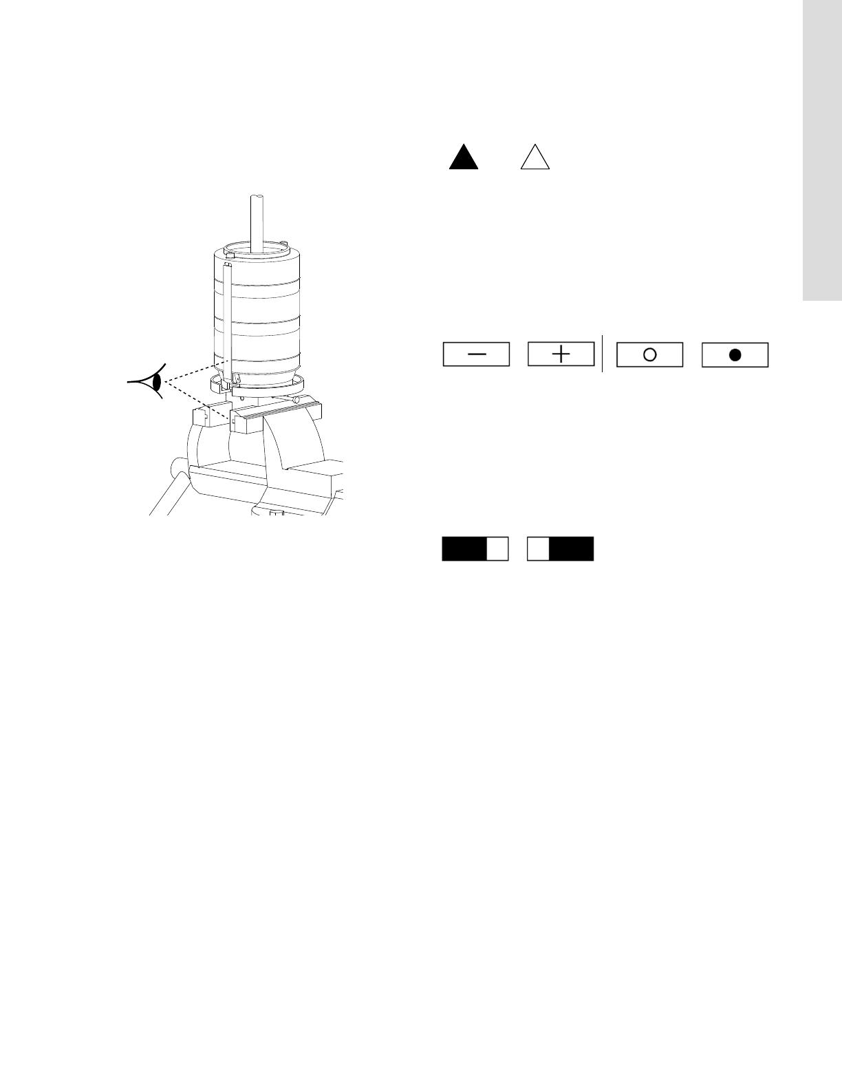
Grundfos CR 64 Service Instructions Manual

Type
Service Instructions Manual

This manual is also suitable for

GRUNDFOS INSTRUCTIONS
CR, CRN 32-90 Model B
Standard model
Service instructions
3
English (US)
3. Service tools
ABC
DEF
GH I
JKL
MNO
PQ
Pos. Designation For pos. Tool size Product No
A
Ring/open-
end spanner
18, 23 24 mm SV0122
28 8 mm SV0273
36 24 mm SV0122
B
Rubber
hammer
SV0349
C Hexagon key
9 8 mm SV0032
113 3 mm -
28 8 mm SV0032
58a 8 mm SV0032
D
Torque
screwdriver
113, 7a
.1-4 ft.-lbs./
1-6 Nm
SV0435
SV0438
E Hexagon bit
98 mm -
113 3 mm -
28 8 mm -
F
Torque
wrench
9, 18, 23,
28, 36, 58
15-74 ft.-lbs./
20-100 Nm
SV0269
G
Ring insert
tool
18, 23 24 mm SV0524
28 8 mm SV0411
36 24 mm SV0524
H
Key for split
cone nut
48 34 mm SV0004
I
Tap for key
for split cone
nut
48-K
14 mm
9 x 12 mm
SV0403
J
Holder with
pin for
dismantling
and
assembly
80 -
CR, CRN 32
SV0003-3
CR, CRN 45
SV0003-4
CR, CRN 64
SV0003-5
CR, CRN 90
SV0003-2
K
Holder for
wear ring
49c -
CR, CRN 32
SV0043
CR, CRN 45
SV0044
CR, CRN 64
SV0045
CR, CRN 90
SV0046
L
Puller for
wear ring
49c - SV0239
M
Punch for
complete
neck ring
45a -
CR, CRN 32
SV0025
CR, CRN 45
SV0027
CR, CRN 64
SV0028
CR, CRN 90
SV0029
N
Punch for
bush
47c-47d - SV0015
O
Ho
ok
spanner
49-49a - SV
0031
P
Adjusting
fork
105 22 mm 985924
Q Eye bolt 28b ID2779
English (US)
4
4. Torques
5. Lubricants
6. Pump dismantling
Position numbers refer to the drawings in section 11. Exploded
views.
6.1 Motor
1. Remove screws (pos. 7a) and coupling guards (pos. 7).
2. Remove screws (pos. 9) and coupling (pos. 8). It may be
necessary to loosen the coupling with a rubber hammer.
3. Remove screws (pos. 28). Lift and remove motor and motor
stool (pos. 1a) with lifting straps that pass through the motor
stool. Ensure that the motor does not tip and the load is not
applied to the pump shaft.
6.2 Shaft seal and pump head
1. Remove screws (pos. 58a) and retainer (pos. 58).
2. Clean end of shaft (pos. 51).
3. Slacken set screws (pos. 113) of shaft seal (pos. 105).
4. Carefully press shaft seal out of pump head (pos. 2) using two
slot screwdrivers, and pull it off the shaft. See fig. 1.
Fig. 1 Removing upper shaft seal
5. Remove nuts (pos. 36) and washers (pos. 66a).
6. Remove pump head (pos. 2). It may be necessary to loosen it
with a rubber hammer.
Pos. Description Dimensions Torque
7a
Coupling guard
screws
- 4.4 ft-lbs./6 Nm
9 Coupling screws M10 x 25 mm 63 ft-lbs./85 Nm
18 Air vent screws -
26 ft-lbs./35 Nm
23 Drain plugs 1/2"
26b Screws for straps - 11 ft-lbs./15 Nm
28 Motor stool screws M10 x 50 mm 46 ft-lbs./62 Nm
36 Pump head nuts M16 74 ft-lbs./100 Nm
48 Spit cone nut - 52 ft-lbs./70 Nm
58a Seal carrier screws M10 x 25 mm 46 ft-lbs./62 Nm
113 Shaft seal set screws - 4 ft-lbs./6 Nm
Pos. Description Lubricant Product No
9 Coupling screws
THREAD-EZE 00SV999728 Motor stool screws
58a Seal carrier screws
51 Shaft
Soapy water -
105 Shaft seal
37 O-ring pump housing
Rocol
Sapphire
Aqua-Sil
00RM2924
47 Bearing ring
109 O-ring shaft seal
110 O-ring shaft seal
Caution
To prevent the motor from tipping over, hold it
straight when using a lifting device.
Do not use the lifting eyes of the motor for lifting
the entire pump and motor assembly.
TM060090 4813
5
English (US)
6.3 Chamber stack
6.3.1 Fitting chamber stack on the holder
1. Place the holder for dismantling and assembly in a vice and
tighten it. See fig. 2 for right positioning.
2. Pull the chamber stack out of the outer sleeves (pos. 55) and
place it in the holder according to fig. 2. Make sure the
chamber stack engages with the holder.
3. Fit the locking pin in the hole marked "Dismantling".
Fig. 2 Positioning the chamber stack in the holder
4. Remove screws (pos. 26b) and washers (pos. 26c).
5. Remove straps (pos. 26a).
6.3.2 Dismantling chambers
Depending on their construction, dismantle the chambers
according to the instructions below. The symbols refer to section
10. Order of assembly for chambers and impellers.
Single chamber
Fig. 3 Single chamber
1. Pull apart the rotating spring of the bearing (pos. 47a) and
remove the bearing.
2. Hold impeller (pos. 49) with the hook spanner, and slacken
split cone nut (pos. 48) using the key for split cone nut. Turn
the key around and knock the nut to loosen the impeller from
the split cone (pos. 49b).
3. Pull the split cone nut, split cone and impeller off the shaft.
Top chamber and chamber without bearing
Fig. 4 Left: top chamber; right: chamber without bearing
1. Loosen chamber (pos. 3) from the chamber below using a
screwdriver, and remove it.
2. Hold impeller (pos. 49) with the hook spanner, and slacken
split cone nut (pos. 48) using the key for split cone nut.
Turn the key around, and knock the nut to loosen the impeller
from split cone (pos. 49b).
3. Pull the split cone nut, split cone and impeller off the shaft.
Chamber with bearing
Fig. 5 Chamber with bearing
1. Loosen chamber (pos. 4a) from the chamber below or inlet
part (pos.44) using a screwdriver.
2. Loosen bearing ring (pos. 47a) from split cone nut (pos. 48)
and pull it off the shaft.
3. Hold impeller (pos. 49) with the hook spanner, and slacken
split cone nut (pos. 48) using the key for split cone nut.
Turn the key around, and knock the nut to loosen the impeller
from split cone (pos. 49b).
4. Pull the split cone nut, split cone and impeller off the shaft.
5. When the last impeller has been removed, inlet part (pos. 44)
can be lifted off the holder.
TM060180 5013
7
English (US)
8.1.2 Assembly
1. Place neck ring (pos. 45) in cup (pos. 46).
2. Fit neck ring retainer (pos. 65) with the four driving dogs
pointing downwards. Turn the neck ring retainer until it
engages with the neck ring.
3. Knock/press the neck ring retainer home against the cup
using the punch for complete neck ring. Check that the
measurement is within the tolerance range. See fig.10.
Fig. 10 Measure distance between retainer and top of cup
4. Fit the complete neck ring in chamber (pos. 4/4a) or inlet part
(pos. 44) and knock/press it home using the punch for
complete neck ring.
8.2 Wear ring (pos. 49c)
8.2.1 Dismantling
1. Fit the holder on the impeller. The wear ring should come out
in the center of the holder. See fig 11.
2. Place the impeller and holder on a flat surface, the wear ring
uppermost.
3. Push the wear ring up and free of the impeller using the puller.
See fig. 11.
Fig. 11 Removing wear ring
8.2.2 Assembly
Press wear ring (pos. 49c) carefully down over impeller skirt
(pos. 49/49a).
8.3 Bush (pos. 47c) and retaining ring (pos. 47d)
8.3.1 Dismantling
Place the chamber on a flat surface, and press the bush and
retaining ring down using the punch for bush.
8.3.2 Assembly
Place the chamber on a level and solid surface with complete
neck ring (pos. 45a) facing downwards, and press the bush and
retaining ring home against the chamber using the punch for
bush.
TM011955 2201
Pump Nominal height, X [in. (mm)]
Tolerance range
[in. (mm)]
CR, CRN 32 0.40" (10.1 mm)
± .007" (0.2 mm)
CR, CRN 45 0.61" (15.5 mm)
CR, CRN 64 0.45" (11.5 mm)
CR, CRN 90 0.48" (12.1 mm)
Note
Note
It should be possible to move the neck ring freely
(sideways) between the neck ring retainer and
the cup.
X
X
TM007233 0996
Caution
Make sure to push the ring straight down against
the impeller skirt. Make sure not to damage the
impeller.
9
English (US)
Single chamber
Fig. 17 Single chamber
1. Fit impeller (pos. 49) and press it home.
2. Fit split cone (pos. 49b) and knock it into the impeller hub
using the key for split cone nut.
3. Hold the impeller with the hook spanner. Fit and tighten split
cone nut (pos. 48).
4. Slide bearing ring (pos. 47a) over the split cone nut. It must
engage with the split cone nut.
5. Fit chamber (pos. 3). Turn it so that the holes for straps are
aligned to the fixing lugs for straps on the inlet part.
6. Press the chamber home against inlet part (pos. 44).
7. Fit straps (pos. 26a) and washers (pos. 26c), and cross-
tighten screws (pos. 26b).
9.2 Pump head and shaft seal
1. Replace rubber springs (pos. 60) and O-ring (pos. 37).
2. Fit pump head (pos. 2) on outer sleeves (pos. 55).
3. Fit washers (pos. 66a) and cross-tighten nuts (36).
4. Carefully press shaft seal (pos. 105) down the shaft and in the
pump head.
5. Fit retainer (pos. 58) and cross-tighten screws (58a).
6. Press the pump shaft home and tighten set screws (pos. 113).
7. Lift the pump shaft and insert the adjusting fork between the
shaft seal driver and its retainer. See fig. 18.
Fig. 18 Fitting adjusting forks
9.3 Motor
1. With lifting straps that pass through the motor stool, lift and fit
the motor and motor stool (pos. 1a) to the pump head (pos. 2).
Ensure that the motor does not tip and the load is not applied
to the pump shaft.
2. Cross-tighten screws (pos. 28).
3. Fit coupling (pos. 8), according to fig. 19 and 20, and tighten
screws (pos. 9).
Fig. 19 Fitting coupling
Fig. 20 Adjusting coupling
4. Remove the adjusting fork, and place it under one of screws
(pos. 58a).
5. Check that the pump shaft can rotate freely.
6. Fit coupling guards (pos. 7) and screws (pos. 7a).
TM060071 4813
Caution
To prevent the motor from tipping over, hold it
straight when using a lifting device.
Do not use the lifting eyes of the motor for lifting
the entire pump and motor assembly.
TM05 7578 1213TM03 9607 4207
English (US)
12
11. Exploded views
Fig. 21 Exploded view, CR, CRN 32, model B
TM058405 2313
13
English (US)
Fig. 22 Exploded view (detailed), CR, CRN 32, model B
TM060570 0514
  • Page 1 1
  • Page 2 2
  • Page 3 3
  • Page 4 4
  • Page 5 5
  • Page 6 6
  • Page 7 7
  • Page 8 8
  • Page 9 9
  • Page 10 10
  • Page 11 11
  • Page 12 12
  • Page 13 13

Grundfos CR 64 Service Instructions Manual

Type
Service Instructions Manual
This manual is also suitable for

Ask a question and I''ll find the answer in the document

Finding information in a document is now easier with AI