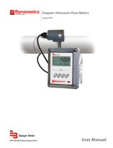
2.013
.732
.732
2.379
.625
.200
.250
Alternate
wall Placement.
Check loop slack.
Door Frame Face
Rim Exit Device
DL-20 Door Loop
2”
4”
Door Loop Base Dimensions
1- Locate the centerline of the door loop on the underside of the Exit Device Housing
4” from sot of frame and 1” from face of door
2- Locate the centerline of the door loop for the face of frame 2” down from the edge of the Exit Device
3- Drill pilot holes (#24 drill) to mount the base and a 5/8” hole for wire conduit.
4- Mount base using #10 SMS.
5- Thread electrical wires through door loop.
6- Install covers with #8 SMS screws
Door Loop exible conduit can be eld cut
THIS DIAGRAM APPLIES TO
all DL Series Door Loops
Mounting Instructions For
“DL20” Door Loops
NOTES: Maximum electrical wires: 7 ea. 18 awg, 10 ea. 22 awg