VES Elite-RS H-Series Installation guide
- Category
- Fire protection
- Type
- Installation guide

Phone: Office +65 6757 7045
Emails: sales@allfireinternational.com

VES, LLC
Elite-RS Panel Installation Manual VF3529-00, Revision E01.03
H-Series
Underwriters Laboratories (UL)
File number (S 8485)
Fire Alarm Equipment
VES, LLC
The VES Elite-RS Panel is suitable as follows:
• Local Signaling Unit
• Releasing for eLAN-RS Panels only. Non-Releasing for Elite-RS Panels.
• Types of signaling services are automatic fire alarm, manual fire alarm, waterflow alarm and sprinkler supervisory.
• Style 4, 6 or 7 for Signaling Line Circuits
• Style Y for Notification Appliance Circuits
• Non-coded Signaling, DACT requires Integrated Dialer
• Remote Station (RS) Protected Premises Unit (PPU) provides releasing, non-releasing and VESNet communication on models
(VFXX24, VFXX44, VFXX04) containing the Modem-DACT Ethernet (VFYY04, VFYY05, VFYY08, VFYY09), integrated Dialer or on models
(VFXX21, VFXX41, VFXX01) containing the Media Gateway
• Central Station (CS) Protected Premises Unit (PPU) provides releasing, non-releasing and VESNet communication on models
(VFXX24, VFXX44, VFXX04) containing the Modem-DACT Ethernet (VFYY04, VFYY05, VFYY08, VFYY09), Integrated Dialer or on models
(VFXX21, VFXX41, VFXX01) containing the Media Gateway
• Models (VFXX22, VFXX42, VFXX02) containing the NIC, must be connected (networked) to the VESNet with models (VFXX21, VFXX41,
VFXX01) containing the Media Gateway to communicate to a Remote Station Protected Premises Unit, Proprietary Protected Premises Unit or
Central Station Protected Premises Unit. The VESNet LCD Display (VF8300) with or without the LED ADD-ON Annunciator (VF8203) may also be
connected to the VESNet (networked) with the above models
• Proprietary (P) Protected Premises Unit (PPU) provides releasing, non-releasing and VESNet communication on models (VFXX24,
VFXX44,VFXX04) containing the Modem-DACT Ethernet, (VFYY04, VFYY05, VFYY08, VFYY09) Integrated Dialer or on models (VFXX21,
VFXX41, VFXX01) containing the Media Gateway
• Remote Station (RS) Protected Premises Unit (PPU) provides releasing, non-releasing and eNet communication on models
(VFXX24, VFXX44, VFXX04) containing the Modem-DACT Ethernet or on models (VFYY04, VFYY05, VFYY08, VFYY09) containing the
integrated Dialer
• Central Station (CS) Protected Premises Unit (PPU) provides releasing, non-releasing and eNet communication on models
(VFXX24, VFXX44, VFXX04) containing the Modem-DACT Ethernet or on models (VFYY04, VFYY05, VFYY08, VFYY09) containing the
Integrated Dialer
• Proprietary (P) Protected Premises Unit (PPU) provides releasing, non-releasing and eNet communication on models
(VFXX24, VFXX44,VFXX04) containing the Modem-DACT Ethernet or on models (VFYY04, VFYY05, VFYY08, VFYY09) containing the
Integrated Dialer
“XX” shown in the model numbering above denotes control panel type where “XX” is “09” for eLAN-RS Panels and “08” for Elite-RS Panels.
“YY” shown in the model numbering above denotes control panel type where “YY” is “04” for H-Series eLAN-RS Panels, “05” for A-Series eLAN-RS
Panels, “08” for H-Series Elite-RS Panels and “09” for A-Series Elite-RS Panels.

VES, LLC
Elite-RS Panel Installation Manual VF3529-00, Revision E01.03
H-Series
FCC
VES, LLC
This equipment complies with Part 68 of the FCC rule and the requirements adopted by the ACTA. On the Inside cover of this equipment is a label that
contains, among other information, a product identifier US:KNTAL00BASA-FACP. If requested, this number must be provided to the telephone company.
The Integrated Dialer is incorporated on the Main Board of the Elite-RS Panel to provide TELCO communication on certain models.
Connect permissive data equipment to TELCO line 1 and line 2 of the Elite-RS Panel using independent RJ31X jacks. Reference Section 3, Installation,
Connecting Communication, page 25 of this manual for details concerning these connections.
Reference the following:
- ATIS Technical Report No. 5 for connector details
- Facility Interface Code 02LS2
- Service Order Code 9.0Y
A plug and jack used to connect this equipment to the premises wiring and telephone network must comply with the applicable FCC Part 68 rules and
requirements adopted by the ACTA. A compliant telephone cord and modular plug must be used. It is designed to be connected to a compatible modular
jack that is also compliant. See installation instructions for details.
This product’s REN is 0,0. The REN is used to determine the number of devices that may be connected to a telephone line. Excessive RENs on a
telephone line may result in the devices not ringing in response to an incoming call. In most but not all areas, the sum of RENs should not exceed five
(5.0). To be certain of the number of devices that may be connected to a line, as determined by the total RENs, contact the local telephone company. The
REN for this product is part of the product identifier that has the format US:AAAEQ##TXXXX. The digits represented by ## are the REN without a
decimal point (e.g., 03 is a REN of 0.3). The REN is separately shown on the door label.
If the terminal equipment Fire Alarm Control Panel causes harm to the telephone network., the telephone company will notify you in advance that
temporary discontinuance of service may be required. But if advance notice is not practical. the telephone company will notify the customer as soon as
possible. Also, you will be advised of your right to file a complaint with the FCC if you believe it is necessary.
The telephone company may make changes in it's facilities. equipment, operations or procedures that could affect the operation of the equipment. If this
happens the telephone company will provide advance notice in order for you to make necessary modifications to maintain uninterrupted service.
If trouble is experienced with this equipment Fire Alarm Control Panel, for repairs or warranty information, please contact VES, LLC 620 Allendale Rd,
King of Prussia, PA. 19406 (800)274-9514. If the equipment is causing harm to the telephone network., the telephone company may request that you
disconnect the equipment until the problem is resolved.
Reference Section 5, Maintenance and Repair of this manual for details describing standby battery and fuse replacement. No other user serviceable
components are contained within this assembly. Contact VES, LLC technical support for diagnostic assistance when necessary. Reference Section 1,
Introduction of this manual for details describing technical support, Return Material Authorization (RMA), Warranty Returns, Advanced Replacements
and the Product Return Address.
Connection to party line service is subject to state tariffs. Contact the state public utility commission, public service commission or corporation
commission for information.
If your home has specially wired alarm equipment connected to the telephone line, ensure the installation of this Fire Alarm Control Panel does not
disable your alarm equipment. If you have questions about what will disable alarm equipment, consult your telephone company or a qualified installer.
Reference the Loop Explorer Configuration Manual, AW-000104, Section 4, Programming, page 10 for details describing the programming of this
assembly.

VES, LLC
Elite-RS Panel Installation Manual VF3529-00, Revision E01.03
H-Series
NFPA
VES, LLC
Install this product in accordance with NFPA 13, NFPA 72 and NEC 70 and all local codes.
Short Circuit Isolator Modules protect SLC loop devices from single-loop-shorts. SLC loops must be wired with Short Circuit Isolator Modules to comply
with NFPA 72, Class A Style 7. SLC loop connections must include closed nippling and conduit nippling to maintain compliance with individual
enclosures under NFPA 72, Class A, Style 7 requirements. Closed nippling encloses individual devices on SLC loops and conduit nippling encloses
wiring between these individual enclosures. For Class A, Style 6 compliance, the Short Circuit Isolator Modules may be located at strategic locations
based on the discretion of the designer or installer.
The NFPA requires that two dedicated and independent TELCO lines feed communication features such as the Integrated Dialer.
Install SLC detectors with spacing as specified in section 90.19 of UL 864, 9th edition where units employing the multiple detector operation shall include
guidelines for installing of a minimum of two detectors in each protected space and to reduce the detector installation spacing to 0.7 times the linear
spacing in accordance with National Fire Alarm Code, NFPA 72. Also reference 55.3.1 and 55.3.2 of UL 864, 9th edition for these detector spacing
requirements.
All field wiring should be installed using fire rated cables according to the NFPA 72. Riser conductors shall be installed in accordance with the
survivability from attack by fire requirements in National Fire Alarm Code, NFPA 72, Sections 6.8.6.3, and 6.9.4. Riser conductors shall employ either a 2
hour rated cable system, or meet requirements approved by the AHJ, or installation of the Supervised Output Module using NFPA Style 7 configuration.”
FM Global Technologies LLC (FM APPROVALS)
VES, LLC

VES, LLC
Elite-RS Panel Installation Manual VF3529-00, Revision E01.03
H-Series
Copyright © 2010 by VES, LLC
All rights reserved.
VES
is a registered trademark of VES, LLC.
All other product or service names are the property of their respective owners.

Contents
i
VES, LLC
Elite-RS Panel Installation Manual VF3529-00, Revision E01.03
H-Series
Section 1
Introduction
Using This Manual . . . . . . . . . . . . . . . . . . . . . . . . . . . . . . . . . . . . . . . . . . . . . . . . . . . . . . . . . . . . 3
Related Documentation . . . . . . . . . . . . . . . . . . . . . . . . . . . . . . . . . . . . . . . . . . . . . . . . . . . . . . . . 3
Document Conventions . . . . . . . . . . . . . . . . . . . . . . . . . . . . . . . . . . . . . . . . . . . . . . . . . . . . . . . . 4
Part Numbers . . . . . . . . . . . . . . . . . . . . . . . . . . . . . . . . . . . . . . . . . . . . . . . . . . . . . . . . . . . . . . 4
Writing styles . . . . . . . . . . . . . . . . . . . . . . . . . . . . . . . . . . . . . . . . . . . . . . . . . . . . . . . . . . . . . . 4
If You Need Help . . . . . . . . . . . . . . . . . . . . . . . . . . . . . . . . . . . . . . . . . . . . . . . . . . . . . . . . . . . . . 4
Contacting VES Tech Support . . . . . . . . . . . . . . . . . . . . . . . . . . . . . . . . . . . . . . . . . . . . . . . . . . 4
RMA Returns Required . . . . . . . . . . . . . . . . . . . . . . . . . . . . . . . . . . . . . . . . . . . . . . . . . . . . . . 4
Warranty Returns . . . . . . . . . . . . . . . . . . . . . . . . . . . . . . . . . . . . . . . . . . . . . . . . . . . . . . . . . . 5
Advanced Replacements. . . . . . . . . . . . . . . . . . . . . . . . . . . . . . . . . . . . . . . . . . . . . . . . . . . . . 5
Product Return Address. . . . . . . . . . . . . . . . . . . . . . . . . . . . . . . . . . . . . . . . . . . . . . . . . . . . . . . 5
Section 2
Overview
Points and Addresses. . . . . . . . . . . . . . . . . . . . . . . . . . . . . . . . . . . . . . . . . . . . . . . . . . . . . . . . . 6
Zone Capability . . . . . . . . . . . . . . . . . . . . . . . . . . . . . . . . . . . . . . . . . . . . . . . . . . . . . . . . . . . . . . 6
Contact ID Address Restrictions . . . . . . . . . . . . . . . . . . . . . . . . . . . . . . . . . . . . . . . . . . . . . . . . 7
Hardware Features . . . . . . . . . . . . . . . . . . . . . . . . . . . . . . . . . . . . . . . . . . . . . . . . . . . . . . . . . . . . 7
NAC Outputs . . . . . . . . . . . . . . . . . . . . . . . . . . . . . . . . . . . . . . . . . . . . . . . . . . . . . . . . . . . . . . . . . 7
Panel Controls and Indicators . . . . . . . . . . . . . . . . . . . . . . . . . . . . . . . . . . . . . . . . . . . . . . . . . . . 8
Left-Panel-Indicators . . . . . . . . . . . . . . . . . . . . . . . . . . . . . . . . . . . . . . . . . . . . . . . . . . . . . . . . 9
Right-Panel Controls . . . . . . . . . . . . . . . . . . . . . . . . . . . . . . . . . . . . . . . . . . . . . . . . . . . . . . . 10
Lower-Control-Pad . . . . . . . . . . . . . . . . . . . . . . . . . . . . . . . . . . . . . . . . . . . . . . . . . . . . . . . . . 11
Settings and Resets . . . . . . . . . . . . . . . . . . . . . . . . . . . . . . . . . . . . . . . . . . . . . . . . . . . . . . . . 12
Terminal Connections . . . . . . . . . . . . . . . . . . . . . . . . . . . . . . . . . . . . . . . . . . . . . . . . . . . . . . . . 12
Internal Power Supply . . . . . . . . . . . . . . . . . . . . . . . . . . . . . . . . . . . . . . . . . . . . . . . . . . . . . . . . 14
Section 3
Installation
General Installation Checklist . . . . . . . . . . . . . . . . . . . . . . . . . . . . . . . . . . . . . . . . . . . . . . . . . . 16
Before You Begin . . . . . . . . . . . . . . . . . . . . . . . . . . . . . . . . . . . . . . . . . . . . . . . . . . . . . . . . . . . 17
Determining System Current Draw . . . . . . . . . . . . . . . . . . . . . . . . . . . . . . . . . . . . . . . . . . . . . .17
Standby-Battery Capacity . . . . . . . . . . . . . . . . . . . . . . . . . . . . . . . . . . . . . . . . . . . . . . . . . . . 17
Operating Constraints . . . . . . . . . . . . . . . . . . . . . . . . . . . . . . . . . . . . . . . . . . . . . . . . . . . . . . . 18

Contents
ii
VES, LLC
Elite-RS Panel Installation Manual VF3529-00, Revision E01.03
H-Series
Mounting the Elite-RS Panel . . . . . . . . . . . . . . . . . . . . . . . . . . . . . . . . . . . . . . . . . . . . . . . . . . . 18
Marking the Location . . . . . . . . . . . . . . . . . . . . . . . . . . . . . . . . . . . . . . . . . . . . . . . . . . . . . . . 18
Anchoring the Cabinet. . . . . . . . . . . . . . . . . . . . . . . . . . . . . . . . . . . . . . . . . . . . . . . . . . . . . . 19
Feeding Cable. . . . . . . . . . . . . . . . . . . . . . . . . . . . . . . . . . . . . . . . . . . . . . . . . . . . . . . . . . . . 19
Replacing Cabinet Components . . . . . . . . . . . . . . . . . . . . . . . . . . . . . . . . . . . . . . . . . . . . . . . 19
Connecting Power and Devices. . . . . . . . . . . . . . . . . . . . . . . . . . . . . . . . . . . . . . . . . . . . . . . . 20
Standby-Batteries . . . . . . . . . . . . . . . . . . . . . . . . . . . . . . . . . . . . . . . . . . . . . . . . . . . . . . . . . 20
Before Wiring and Operating . . . . . . . . . . . . . . . . . . . . . . . . . . . . . . . . . . . . . . . . . . . . . . . . . 22
AC Wiring . . . . . . . . . . . . . . . . . . . . . . . . . . . . . . . . . . . . . . . . . . . . . . . . . . . . . . . . . . . . . . . . 23
Connecting Communication . . . . . . . . . . . . . . . . . . . . . . . . . . . . . . . . . . . . . . . . . . . . . . . . . . . 24
TELCO Communication. . . . . . . . . . . . . . . . . . . . . . . . . . . . . . . . . . . . . . . . . . . . . . . . . . . . . 24
Connecting Class A Loops . . . . . . . . . . . . . . . . . . . . . . . . . . . . . . . . . . . . . . . . . . . . . . . . . . . . 25
NFPA 72, Style 7. . . . . . . . . . . . . . . . . . . . . . . . . . . . . . . . . . . . . . . . . . . . . . . . . . . . . . . . . . 26
NFPA 72, Style 6 . . . . . . . . . . . . . . . . . . . . . . . . . . . . . . . . . . . . . . . . . . . . . . . . . . . . . . . . . . 27
Connecting Class B Loops . . . . . . . . . . . . . . . . . . . . . . . . . . . . . . . . . . . . . . . . . . . . . . . . . . . . 28
Installing SLC Devices . . . . . . . . . . . . . . . . . . . . . . . . . . . . . . . . . . . . . . . . . . . . . . . . . . . . . . . . 28
Detector Spacing . . . . . . . . . . . . . . . . . . . . . . . . . . . . . . . . . . . . . . . . . . . . . . . . . . . . . . . . . . 28
Output Modules Controlling Notification Appliances . . . . . . . . . . . . . . . . . . . . . . . . . . . . . . . 29
Silencing Notification Appliances . . . . . . . . . . . . . . . . . . . . . . . . . . . . . . . . . . . . . . . . . . . . . . 29
NAC Synchronization . . . . . . . . . . . . . . . . . . . . . . . . . . . . . . . . . . . . . . . . . . . . . . . . . . . . . . . 29
Connecting NAC Devices . . . . . . . . . . . . . . . . . . . . . . . . . . . . . . . . . . . . . . . . . . . . . . . . . . . . . 30
Connecting Auxiliary 24 VDC . . . . . . . . . . . . . . . . . . . . . . . . . . . . . . . . . . . . . . . . . . . . . . . . . . 31
Relay Contacts . . . . . . . . . . . . . . . . . . . . . . . . . . . . . . . . . . . . . . . . . . . . . . . . . . . . . . . . . . . . 31
Installing Municipal Boxes . . . . . . . . . . . . . . . . . . . . . . . . . . . . . . . . . . . . . . . . . . . . . . . . . . . . 32
Testing the Installation . . . . . . . . . . . . . . . . . . . . . . . . . . . . . . . . . . . . . . . . . . . . . . . . . . . . . . . 33
Confirming a Successful Installation . . . . . . . . . . . . . . . . . . . . . . . . . . . . . . . . . . . . . . . . . . . . 33
Testing the Panel Lamps . . . . . . . . . . . . . . . . . . . . . . . . . . . . . . . . . . . . . . . . . . . . . . . . . . . . 35
Trouble-Silence Test . . . . . . . . . . . . . . . . . . . . . . . . . . . . . . . . . . . . . . . . . . . . . . . . . . . . . . . 35
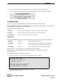
Troubleshooting . . . . . . . . . . . . . . . . . . . . . . . . . . . . . . . . . . . . . . . . . . . . . . . . . . . . . . . . . . . . . 37
Test Zones . . . . . . . . . . . . . . . . . . . . . . . . . . . . . . . . . . . . . . . . . . . . . . . . . . . . . . . . . . . . . . . 37
Event Log . . . . . . . . . . . . . . . . . . . . . . . . . . . . . . . . . . . . . . . . . . . . . . . . . . . . . . . . . . . . . . . . 40
Loop Data Test . . . . . . . . . . . . . . . . . . . . . . . . . . . . . . . . . . . . . . . . . . . . . . . . . . . . . . . . . . . . 44

Contents
iii
VES, LLC
Elite-RS Panel Installation Manual VF3529-00, Revision E01.03
H-Series
Section 4
Front-Panel Menu
Access Level 2. . . . . . . . . . . . . . . . . . . . . . . . . . . . . . . . . . . . . . . . . . . . . . . . . . . . . . . . . . . . . . 49
Disablements . . . . . . . . . . . . . . . . . . . . . . . . . . . . . . . . . . . . . . . . . . . . . . . . . . . . . . . . . . . . . 49
View Devices. . . . . . . . . . . . . . . . . . . . . . . . . . . . . . . . . . . . . . . . . . . . . . . . . . . . . . . . . . . . . 51
Test Zones . . . . . . . . . . . . . . . . . . . . . . . . . . . . . . . . . . . . . . . . . . . . . . . . . . . . . . . . . . . . . . . 51
Set System Time . . . . . . . . . . . . . . . . . . . . . . . . . . . . . . . . . . . . . . . . . . . . . . . . . . . . . . . . . . 52
Sensor Maintenance Early Warning . . . . . . . . . . . . . . . . . . . . . . . . . . . . . . . . . . . . . . . . . . . . 52
Events and Status . . . . . . . . . . . . . . . . . . . . . . . . . . . . . . . . . . . . . . . . . . . . . . . . . . . . . . . . . 52
Access Level 3 . . . . . . . . . . . . . . . . . . . . . . . . . . . . . . . . . . . . . . . . . . . . . . . . . . . . . . . . . . . . . . 53
Front-Panel Controls. . . . . . . . . . . . . . . . . . . . . . . . . . . . . . . . . . . . . . . . . . . . . . . . . . . . . . . . . 55
Alarm Silence . . . . . . . . . . . . . . . . . . . . . . . . . . . . . . . . . . . . . . . . . . . . . . . . . . . . . . . . . . . . . 55
Re-Sound Alarm . . . . . . . . . . . . . . . . . . . . . . . . . . . . . . . . . . . . . . . . . . . . . . . . . . . . . . . . . . 55
Reset . . . . . . . . . . . . . . . . . . . . . . . . . . . . . . . . . . . . . . . . . . . . . . . . . . . . . . . . . . . . . . . . . . . 55
Fire Drill . . . . . . . . . . . . . . . . . . . . . . . . . . . . . . . . . . . . . . . . . . . . . . . . . . . . . . . . . . . . . . . . . 55
Programmable Function . . . . . . . . . . . . . . . . . . . . . . . . . . . . . . . . . . . . . . . . . . . . . . . . . . . . . 55
Section 5
Maintenance and Repair
Maintenance . . . . . . . . . . . . . . . . . . . . . . . . . . . . . . . . . . . . . . . . . . . . . . . . . . . . . . . . . . . . . . . . 56
Inspecting Batteries . . . . . . . . . . . . . . . . . . . . . . . . . . . . . . . . . . . . . . . . . . . . . . . . . . . . . . . . 56
Replacing Standby-Batteries . . . . . . . . . . . . . . . . . . . . . . . . . . . . . . . . . . . . . . . . . . . . . . . . . 56
Replacing Fuses . . . . . . . . . . . . . . . . . . . . . . . . . . . . . . . . . . . . . . . . . . . . . . . . . . . . . . . . . . . . 58
10 Amp Battery Fuse. . . . . . . . . . . . . . . . . . . . . . . . . . . . . . . . . . . . . . . . . . . . . . . . . . . . . . . 58
3 Amp Power-Supply Fuse . . . . . . . . . . . . . . . . . . . . . . . . . . . . . . . . . . . . . . . . . . . . . . . . . . 59
Removing Cabinet Components . . . . . . . . . . . . . . . . . . . . . . . . . . . . . . . . . . . . . . . . . . . . . . . 60
Appendix A
Specifications
Electrical . . . . . . . . . . . . . . . . . . . . . . . . . . . . . . . . . . . . . . . . . . . . . . . . . . . . . . . . . . . . . . . . . . . 64
Standby and Alarm Current . . . . . . . . . . . . . . . . . . . . . . . . . . . . . . . . . . . . . . . . . . . . . . . . . . 64
Earth Fault Indication . . . . . . . . . . . . . . . . . . . . . . . . . . . . . . . . . . . . . . . . . . . . . . . . . . . . . . . 64
SLC Ratings . . . . . . . . . . . . . . . . . . . . . . . . . . . . . . . . . . . . . . . . . . . . . . . . . . . . . . . . . . . . . . 64
SLC Cabling . . . . . . . . . . . . . . . . . . . . . . . . . . . . . . . . . . . . . . . . . . . . . . . . . . . . . . . . . . . . . . 65
Programmable Relay Contacts . . . . . . . . . . . . . . . . . . . . . . . . . . . . . . . . . . . . . . . . . . . . . . . . 65
NAC Outputs . . . . . . . . . . . . . . . . . . . . . . . . . . . . . . . . . . . . . . . . . . . . . . . . . . . . . . . . . . . . . 66
RS485 Serial Bus . . . . . . . . . . . . . . . . . . . . . . . . . . . . . . . . . . . . . . . . . . . . . . . . . . . . . . . . . . 67
eNET Terminals . . . . . . . . . . . . . . . . . . . . . . . . . . . . . . . . . . . . . . . . . . . . . . . . . . . . . . . . . . . 67

Contents
iv
VES, LLC
Elite-RS Panel Installation Manual VF3529-00, Revision E01.03
H-Series
24 V OUT . . . . . . . . . . . . . . . . . . . . . . . . . . . . . . . . . . . . . . . . . . . . . . . . . . . . . . . . . . . . . . . . 67
Auxiliary 24 VDC . . . . . . . . . . . . . . . . . . . . . . . . . . . . . . . . . . . . . . . . . . . . . . . . . . . . . . . . . . 68
AC Line Connection . . . . . . . . . . . . . . . . . . . . . . . . . . . . . . . . . . . . . . . . . . . . . . . . . . . . . . . . 68
Power Supply . . . . . . . . . . . . . . . . . . . . . . . . . . . . . . . . . . . . . . . . . . . . . . . . . . . . . . . . . . . . . 68
Cabling . . . . . . . . . . . . . . . . . . . . . . . . . . . . . . . . . . . . . . . . . . . . . . . . . . . . . . . . . . . . . . . . . . 69
Operating Environment . . . . . . . . . . . . . . . . . . . . . . . . . . . . . . . . . . . . . . . . . . . . . . . . . . . . . . . 70
Physical Specifications . . . . . . . . . . . . . . . . . . . . . . . . . . . . . . . . . . . . . . . . . . . . . . . . . . . . . . . 70
Appendix B
Equipment List
VES Elite-RS Panels . . . . . . . . . . . . . . . . . . . . . . . . . . . . . . . . . . . . . . . . . . . . . . . . . . . . . . . . . . 72
Loop Devices and Accessories . . . . . . . . . . . . . . . . . . . . . . . . . . . . . . . . . . . . . . . . . . . . . . . . . 73
Replacement Parts . . . . . . . . . . . . . . . . . . . . . . . . . . . . . . . . . . . . . . . . . . . . . . . . . . . . . . . . . . . 75
Notification Appliances . . . . . . . . . . . . . . . . . . . . . . . . . . . . . . . . . . . . . . . . . . . . . . . . . . . . . . 76
Synchronization . . . . . . . . . . . . . . . . . . . . . . . . . . . . . . . . . . . . . . . . . . . . . . . . . . . . . . . . . . . 77
Configuring NAC Outputs . . . . . . . . . . . . . . . . . . . . . . . . . . . . . . . . . . . . . . . . . . . . . . . . . . . . 77
Regulated NAC Outputs . . . . . . . . . . . . . . . . . . . . . . . . . . . . . . . . . . . . . . . . . . . . . . . . . . . . 78
Special Application NAC Outputs . . . . . . . . . . . . . . . . . . . . . . . . . . . . . . . . . . . . . . . . . . . . . . 79
Maximum Line Impedance . . . . . . . . . . . . . . . . . . . . . . . . . . . . . . . . . . . . . . . . . . . . . . . . . . . 92
Compatible Devices for Auxiliary 24V . . . . . . . . . . . . . . . . . . . . . . . . . . . . . . . . . . . . . . . . . . 92
Appendix C
Calculations
Current-Loading . . . . . . . . . . . . . . . . . . . . . . . . . . . . . . . . . . . . . . . . . . . . . . . . . . . . . . . . . . . . . 94
Example of Total Load Current . . . . . . . . . . . . . . . . . . . . . . . . . . . . . . . . . . . . . . . . . . . . . . . . 95
Determining the Standby-Battery Rating . . . . . . . . . . . . . . . . . . . . . . . . . . . . . . . . . . . . . . . . . 96
Battery Rating Equation . . . . . . . . . . . . . . . . . . . . . . . . . . . . . . . . . . . . . . . . . . . . . . . . . . . . . 96
Tabulating Data . . . . . . . . . . . . . . . . . . . . . . . . . . . . . . . . . . . . . . . . . . . . . . . . . . . . . . . . . . . 97
NAC Wiring Length . . . . . . . . . . . . . . . . . . . . . . . . . . . . . . . . . . . . . . . . . . . . . . . . . . . . . . . . . . . 98
Sample Lmax Calculation . . . . . . . . . . . . . . . . . . . . . . . . . . . . . . . . . . . . . . . . . . . . . . . . . . . . 98
Contact ID . . . . . . . . . . . . . . . . . . . . . . . . . . . . . . . . . . . . . . . . . . . . . . . . . . . . . . . . . . . . . . . . . 106
Zone ID Reporting . . . . . . . . . . . . . . . . . . . . . . . . . . . . . . . . . . . . . . . . . . . . . . . . . . . . . . . . 106
Point ID Reporting . . . . . . . . . . . . . . . . . . . . . . . . . . . . . . . . . . . . . . . . . . . . . . . . . . . . . . . . 106
Appendix D
Door Label
Appendix E
Operating Instructions

Contents
v
VES, LLC
Elite-RS Panel Installation Manual VF3529-00, Revision E01.03
H-Series
Appendix F
Communications Format
SIA. . . . . . . . . . . . . . . . . . . . . . . . . . . . . . . . . . . . . . . . . . . . . . . . . . . . . . . . . . . . . . . . . . . . . . . 107
Zone ID Reporting . . . . . . . . . . . . . . . . . . . . . . . . . . . . . . . . . . . . . . . . . . . . . . . . . . . . . . . . 107
Point ID Reporting . . . . . . . . . . . . . . . . . . . . . . . . . . . . . . . . . . . . . . . . . . . . . . . . . . . . . . . . 107
Dialing Methodology . . . . . . . . . . . . . . . . . . . . . . . . . . . . . . . . . . . . . . . . . . . . . . . . . . . . . . . . 107
Dialing Facilities . . . . . . . . . . . . . . . . . . . . . . . . . . . . . . . . . . . . . . . . . . . . . . . . . . . . . . . . . . 107
Dialing Sequence . . . . . . . . . . . . . . . . . . . . . . . . . . . . . . . . . . . . . . . . . . . . . . . . . . . . . . . . . 107
Answering Methodology. . . . . . . . . . . . . . . . . . . . . . . . . . . . . . . . . . . . . . . . . . . . . . . . . . . . . 108
24 Hour Test Report . . . . . . . . . . . . . . . . . . . . . . . . . . . . . . . . . . . . . . . . . . . . . . . . . . . . . . . . 108
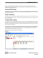
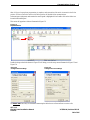
Configure Dialer Settings . . . . . . . . . . . . . . . . . . . . . . . . . . . . . . . . . . . . . . . . . . . . . . . . . . . . 108
Phone Numbers . . . . . . . . . . . . . . . . . . . . . . . . . . . . . . . . . . . . . . . . . . . . . . . . . . . . . . . . . . 110
Dialing . . . . . . . . . . . . . . . . . . . . . . . . . . . . . . . . . . . . . . . . . . . . . . . . . . . . . . . . . . . . . . . . . . 111
Use Lines . . . . . . . . . . . . . . . . . . . . . . . . . . . . . . . . . . . . . . . . . . . . . . . . . . . . . . . . . . . . . . . 111
Number of rings before Answer. . . . . . . . . . . . . . . . . . . . . . . . . . . . . . . . . . . . . . . . . . . . . . 111
Test Code Time . . . . . . . . . . . . . . . . . . . . . . . . . . . . . . . . . . . . . . . . . . . . . . . . . . . . . . . . . . 111
Report By Zone or by Point. . . . . . . . . . . . . . . . . . . . . . . . . . . . . . . . . . . . . . . . . . . . . . . . . 111
Protocol . . . . . . . . . . . . . . . . . . . . . . . . . . . . . . . . . . . . . . . . . . . . . . . . . . . . . . . . . . . . . . . . 111
Account Number . . . . . . . . . . . . . . . . . . . . . . . . . . . . . . . . . . . . . . . . . . . . . . . . . . . . . . . . . . 111
Reporting Criteria . . . . . . . . . . . . . . . . . . . . . . . . . . . . . . . . . . . . . . . . . . . . . . . . . . . . . . . . . 111
Suspending Reporting. . . . . . . . . . . . . . . . . . . . . . . . . . . . . . . . . . . . . . . . . . . . . . . . . . . . . 112
Appendix G
Reporting Formats
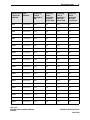
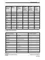
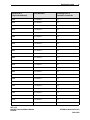
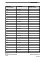
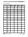
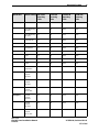
SIA Point Conversion . . . . . . . . . . . . . . . . . . . . . . . . . . . . . . . . . . . . . . . . . . . . . . . . . . . . . . . . 114
Contact ID Conversion . . . . . . . . . . . . . . . . . . . . . . . . . . . . . . . . . . . . . . . . . . . . . . . . . . . . . . 125
Event Code Translation . . . . . . . . . . . . . . . . . . . . . . . . . . . . . . . . . . . . . . . . . . . . . . . . . . . . . . 136
This page intentionally left blank.

Introduction 1
VES, LLC
Elite-RS Panel Installation Manual VF3529-00, Revision E01.03
H-Series 1 of 145
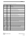
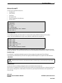
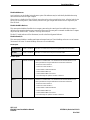
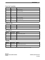
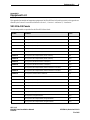
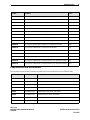
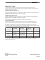
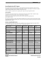
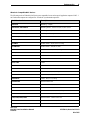
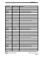
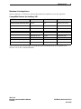
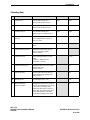
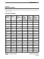
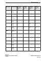
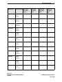
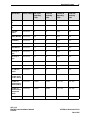
Notice to users, installers, authorities having jurisdiction, and other involved parties.
This product incorporates field-programmable software. In order for the product to comply with the requirements in
the Standard for Control Units and Accessories for Fire Alarm Systems, UL 864 9th Edition, certain programming
features or options must be limited to specific values or not used at all as indicated below.
Reference Appendix B, “Equipment List” for the specific models described in this table.
Program Feature or Option Permitted in UL 864 ?
(Y / N) Possible Settings Settings Permitted
In UL 864
AC Fail Delay Yes 0 - 24 hours 1 - 3 hours
Alarm Verification Yes 5 - 60 seconds 60 second
Disable Buzzer Yes Enable / Disable Enable
Disable Ground Trouble Yes Enable / Disable Enable
Set Buzzer Silence Access Level Yes 1 or 2 2
NAC Output Delay Stage 1 No 0 - 5 minutes 0 minutes
NAC Output Delay Stage 2 No 0 - 5 minutes 0 minutes
Photoelectric Smoke Sensor
Delay Yes 0 -120 seconds 0 seconds
Ionization Smoke Sensor Delay Yes 0 -120 seconds 0 seconds
Duct Detector Yes 0 -120 seconds 0 seconds
Duct Detector with Relay Yes 0 -120 seconds,
0 - 5 seconds 0 seconds
Contact Module Delay
(All models) Yes 0 -120 seconds 0 seconds
Conventional Zone Module Delay Yes 0 -120 seconds 0 seconds
Dual Relay Module Delay Yes 0 - 5 seconds 0 seconds
Supervised Output Module Delay Yes 0 - 5 seconds 0 seconds
Section 1
Introduction

Introduction 1
VES, LLC
Elite-RS Panel Installation Manual VF3529-00, Revision E01.03
H-Series 2 of 145
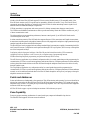
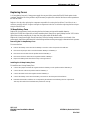
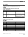
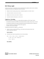
This manual describes 1 and 2 loop models of the VES Elite-RS H-Series Panel. All models of the Elite-RS H-Series
support Hochiki protocol.
One loop models include the No Communication VF0810, the Non-Expandable, No Communication VF0830, the
Media Gateway VF0811, the Non-Expandable, Media Gateway VF0831, the Network Interface Card (NIC) VF0812,
the Non-Expandable, Network Interface Card (NIC) VF0832, the Modem-DACT Ethernet VF0814, the
Non-Expandable, Modem-DACT Ethernet VF0834, the eNet Interface VF0815, the Integrated Dialer VF0816,
the Non-Expandable, Integrated Dialer VF0836 and the eNet Interface & Integrated Dialer VF0817.
Two loop models include the No Communication with Loop Expansion Module VF0820, the Media Gateway with
Loop Expansion Module VF0821, the NIC with Loop Expansion Module VF0822, the Modem-DACT Ethernet
VF0824, the eNet Interface VF0825, the Integrated Dialer VF0826 and the eNet Interface & Integrated Dialer
VF0827.
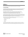
This section describes:
• Using This Manual
• Related Documentation
• Document Conventions
• If You Need Help
• Contacting VES For Repair
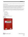
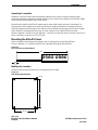
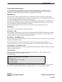
The figure below illustrates the Elite-RS Panel:
Figure 1-1
Elite-RS Panel

Introduction 1
VES, LLC
Elite-RS Panel Installation Manual VF3529-00, Revision E01.03
H-Series 3 of 145
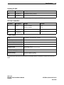
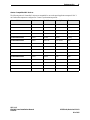
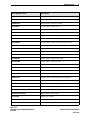
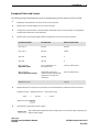
Using This Manual
The following sections provide instructions for installing, testing and troubleshooting the Elite-RS Panel:
Related Documentation
The following documents shall be used to provide additional information for installing the Elite-RS Panel:
• Modem-DACT Ethernet Installation Manual, VF1628-00, Rev. E02.XX
• Media Gateway Installation Manual VF1627-00, Rev. E02.XX
• Network Interface Card (NIC) Installation Manual VF1629-00, Rev. E02.XX
• 16 Channel I/O Interface Installation Manual, VF3512-00, E01.XX
• eView Installation Manual, VF3510-00, E01.XX
• eMatrix Installation Manual, VF3513-00, E01.XX
• eNet Installation Manual, VF3511-00, E01.XX
Section 1 Introduction provides document conventions, the technical help-line, repair and return
information.
Section 2 Overview provides a summary features of the Elite-RS Panel.
Section 3 Installation describes how to setup, install and test the Elite-RS Panel.
Section 4 Front-Panel Menu describes how to operate the Elite-RS Panel from its front-panel.
Section 5 Maintenance and Repair describes how to maintain and repair the Elite-RS Panel.
Appendix A Specifications provides characteristics of the Elite-RS Panel.
Appendix B Equipment List provides model numbers for VES Elite-RS Panels, loop devices, accessories,
replacement parts and compatible Notification Appliances.
Appendix C Calculations provides calculations for determining load capacity, battery rating, and wiring length
of the Elite-RS Panel.
Appendix D Front Door Label is a copy of the Elite-RS Panel front door label.
Appendix E Operating Instructions provides an overview of Elite-RS Panel status and control instructions.
Appendix F Communication Formats describes settings and characteristics of the embedded dialer.
Appendix G Reporting Formats contains tables for SIA point conversion, Contact ID conversion and
Event Code translation.

Introduction 1
VES, LLC
Elite-RS Panel Installation Manual VF3529-00, Revision E01.03
H-Series 4 of 145
Document Conventions
This document contains conventions for part numbers and writing style.
Part Numbers
Part numbers are provided in Section 1, Appendix B and Appendix D of this manual. Refer to Appendix D,
Door Label for a diagram summary of this manual. Refer to Appendix B, Equipment List for a complete list of part
numbers required for completing this installation.
Writing styles
Before you begin using the Elite-RS Panel, familiarize yourself with the stylistic conventions used in this manual:
If You Need Help
If you need technical support contact VES at (800) 274 - 9514 or email [email protected].
VES technical support is available Monday through Friday, 9:00 AM to 6:00 PM, Eastern Standard Time.
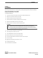
Contacting VES Tech Support
On-site technicians familiar with the product issue should contact VES Tech Support and include the:
• Product part number
• Purchase order or VES order number
• Product serial number
• Current function of the product
• Expected function of the product
• Installation of the product
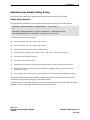
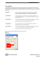
RMA Returns Required
A Return Material Authorization (RMA) must be assigned to all products returning to VES. VES Tech Support will
assign an RMA to a returning product after recording information collected from the on-site technician. VES cannot
not accept product-returns that do not include an accompanying RMA number.
An RMA number is assigned when:
• A product issue is acknowledged by a VES Tech Support representative
• A product was damaged during shipping
• An incorrect product was shipped
• An order was placed using an incorrect part number *
• An order was placed using an incorrect part quantity *
• An order is no longer required *
* Restocking fees may apply.
Italic type Denotes a displayed variable, a variable that you must type, or is used for emphasis.
Courier font Indicates text displayed on a computer screen.

Introduction 1
VES, LLC
Elite-RS Panel Installation Manual VF3529-00, Revision E01.03
H-Series 5 of 145
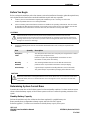
Warranty Returns
VES Tech Support can replace a defective product when the original purchase is within the warranty period defined
in the sales contract. Check your sales-contract for more information or contact your VES sales representative about
the warranty period described in your sales-contract.
Warranty products that have been placed in service will be repaired or replaced by VES.
Warranty products that have not been placed in service will be returned to VES stock and an equivalent credit will be
provided to the contractor.
Advanced Replacements
Suspect-products that fail to operate in the field can be replaced quickly using the advanced replacement process.
The advanced replacement process is available to all contractors who maintain an acceptable line of credit with VES.
Initiate the advanced replacement process by requesting an RMA number from a VES Tech Support representative.
Advanced replacements can be shipped to your location when the suspect-product is covered under warranty and
when a replacement product is in stock. All advanced replacement products are shipped UPS ground.
Expedited Replacements
Advanced replacements can be expedited at the request of the contractor. Shipping costs associated with this
process are the responsibility of the contractor.
Returning Products
Products returning to VES using the advanced replacement process must be received 30 days from the RMA issue-
date. Contractors can be billed for returning products received following this 30 day period.
Product Testing
Products returned to VES are tested to confirm operating failures experienced in the field.
If the suspect-product is found to be functional, contractors must absorb expenses for:
• Shipping of the advanced replacement product
• Return-shipping of the original product
• Cost of the advanced replacement product
Product Return Address
Prominently display the RMA number on all packages sent to VES for return.
Ship all return products to:
Attention: RMA # _____________
VES, LLC
620 Allendale Road, Suite 175
King of Prussia, PA. 19406

Overview 2
VES, LLC
Elite-RS Panel Installation Manual VF3529-00, Revision E01.03
H-Series 6 of 145
Models of the H-Series Elite-RS Panel support SLC devices using Hochiki protocol. The standard model of the
Elite-RS Panel contains one SLC loop and may be expanded to include a second SLC Loop. The Elite-RS Panel
supports the networking flexibility of either the eNet or the VESNet. In either networking scenario signals for all
network nodes are transmitted through a single dialer.
VESNet networking is a proprietary and secure protocol for linking communication between control panels.
The VESNet uses embedded communication-cards to provide networking. Obtain the VESNet connection at jack J3
of these communication-cards.
The eNet provides a secure networking architecture, between control panels. Up to 64 Elite-RS Panels can be
connected together on the eNet.
In either networking scenario; Elite-RS Panels also supports Remote LCD Annunciators and Graphic Annunciators.
Annunciators (repeater panels) and graphical annunciators are fully supported in multiple or single quantities through
standard communication bus included with the panel.
The Elite-RS Panel can be equipped with an industry standard digital communicator capable of transmitting both SIA
and Contact ID formats. Configurations can be performed through VES Loop Explorer, eSP Discovery or through the
use of the front-panel soft-keys.
Configuring with the front-panel soft-keys of the Elite-RS provides limited functionality. VES recommends
configuring with Loop Explorer or esP Discovery for a complete range of programming features.
VESNet networking and panel programming are performed through eSP Discovery.
The eSP Discovery application is a web based configuration utility for control panels that provides programming for
communication, SLC devices, notification appliances and initiation devices. Configure parameters for these attributes
on the web and then download them to the Elite-RS Panel through the telephone connection to the dialer or locally
through Transfer Agent.
The Loop Explorer application is a configuration utility for control panels that provides programming for
communication, SLC devices, notification appliances and initiation devices. Configure parameters for these attributes
remotely or on-site and then download them to the Elite-RS Panel through the serial port of your laptop or through a
telephone connection to the dialer.
Points and Addresses
Points and addresses are fundamental to the operation of Elite-RS monitoring and reporting. Devices are identified as
points when connected to the Elite-RS Panel. Each Elite-RS Panel supports a maximum of 127 points per loop plus
subpoints on any module or 252 points per loop when utilizing subpoints. The 1 and 2 loop Elite-RS Panel supports a
maximum of 800 devices per panel.
All Elite-RS Panels support a point and subpoint maximum of 800 addresses per panel.
Zone Capability
Zones are groups containing combinations of control panel input, output and addressable loop devices.
The Elite-RS Panel supports 500 zones across the network.
Section 2
Overview

Overview 2
VES, LLC
Elite-RS Panel Installation Manual VF3529-00, Revision E01.03
H-Series 7 of 145
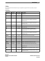
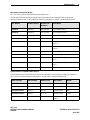
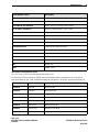
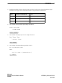
Contact ID Address Restrictions
Address reporting restrictions affect all models of the Elite-RS Panel when using the Contact ID format.
The Contact ID format limits reporting to addresses of 99 and above. The format employs three digits in the protocol.
The first digit is reserved for the loop number and the remaining digits are reserved for addressing.
Allocation of the first digit is described below:
The Contact ID format can be used for devices as long as the device address is 99 or below. Using contact ID protocol
with point reporting will result in truncation of data for points above 99.
FACP reporting can be changed from point reporting to zone reporting when the limit of 99 addresses per loop
cannot be avoided. Zone reporting can be used to resolve address assignments in excess of 99 but doing so reduces
overall reporting granularity.
Models of the Elite-RS Panel can be programmed for the SIA or Contact ID digital communication format. The SIA
and Contact ID format provide status monitoring and reporting to industry-standard receivers at the
monitoring-center.
Both of these digital communication formats provide a range of addressing for device-points and sub-points on the
Elite-RS Panel. The SIA format allows full reporting from all device-points and sub-points. The Contact ID format
provides a limited range of reporting from device-points.
Reference Appendix B, “Equipment List” for all models affected by restrictions of the Contact ID format.
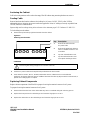
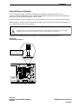
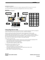
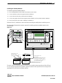
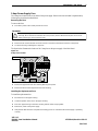
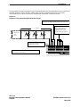
Hardware Features
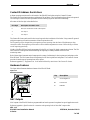
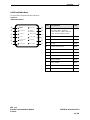
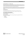
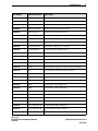
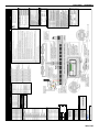
The figure below illustrates hardware features of the Elite-RS Panel:
Figure 2-1
Hardware Features\
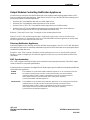
NAC Outputs
NAC outputs of the Elite-RS Panel are programmable and can be operated in regulated or special application mode.
Reference Appendix A, Specifications for constraints and operating levels of these NAC output modes.
First digit Description of numeric value
0 Zero I/O connections on the control panel
1 SLC loop 1
2 SLC loop 2
Key Description
AGrounding Block
BFront-Panel
CBatteries
E E
P2R
P2T
L2R
L2T
P1R
P1T
L1R
L1T
Alarm
Sile nce Panel Sounder
Silence Lamp
Test Re set Fire Dril l Programmable
Function
Enable Access
Re-Sou nd
Alarm
Fire
AC Power On
Pre-A larm
On Test
More Events
General
Disabl ement
General Trouble
Power Trouble
Supervisory
NAC Trou bl e
More
Fire Events Mo re
Events
Enter
Exit
24V OUT AUX 24V
+-
+-
NC C NO
TROUBLE
NC C N O
FIRE
NC C N O
SUPERVISORY
NAC 1 NAC2
+-+-
NET OUT NET IN
+-
+-
COMMS
+-
SLC1 OUT SLC1 IN
+-+-
A
C POWER
L N E
Battery
Connection
+
-
JP1
PC
PC / Dialer
Reset Watchdog
Operated Contrast
Watc hdog
Reset
SLC2 OUT SLC2 IN
+-+-
1
2
3
4?
1 2 3 4 5 6 7 8 9 10 11 12 13 14 15 16 17 18 19 20 21 22 23 24 25 26 27 28 29 30 31 32 33 34 35 36 37
38 39 40 41
Panel Sounder
Silenced
Delay Active
C
A
B

Overview 2
VES, LLC
Elite-RS Panel Installation Manual VF3529-00, Revision E01.03
H-Series 8 of 145
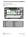
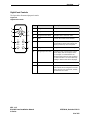
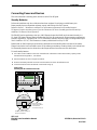
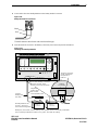
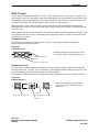
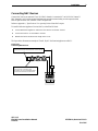
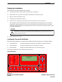
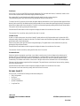
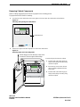
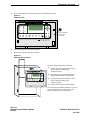
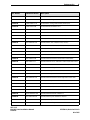
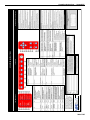
Panel Controls and Indicators
The figure below illustrates controls and indicators of the Elite-RS Panel:
Figure 2-2
Controls and Indicators
Key Description Key Description
A Terminal connections F AC power connections
B Left-panel-indicators G Settings and controls
C Lower-control-pad H Right-panel-controls and indicators
D PC connection I LCD Display
E Battery connection J JP1 connection
E E
P2R
P2T
L2R
L2T
P1R
P1T
L1R
L1T
Alarm
Silence Panel Sounder
Silence Lamp
Test Reset Fire Drill Programmable
Function
Enable Access
Re-Sound
Alarm
Fire
AC Power On
Pre-Alarm
On Test
More Events
General
Disablement
General Trouble
Power Trouble
Supervisory
NAC Trouble
More
Fire Events More
Events
EnterExit
24V OUTAUX 24V
+-
+- NC C NO
TROUBLE
NC C NO
FIRE
NC C NO
SUPERVISORYNAC 1 NAC2
+-+-
NET OUT NET IN
+-+-
COMMS
+-
SLC1 OUT SLC1 IN
+-+-
AC POWER
L N E
Battery
Connection
+ -
JP1
PC PC / Dialer Reset Watchdog
Operated Contrast
Watchdog
Reset
SLC2 OUT SLC2 IN
+-+-
1
2
3
4?
1 2 3 4 5 6 7 8 9 10 11 12 13 14 15 16 17 18 19 20 21 22 23 24 25 26 27 28 29 30 31 32 33 34 35 36 37
38 39 40 41
A
B
C
D
E F
G
H
I
J
Panel Sounder
Silenced
Delay Active

Overview 2
VES, LLC
Elite-RS Panel Installation Manual VF3529-00, Revision E01.03
H-Series 9 of 145
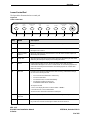
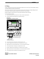
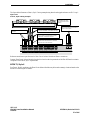
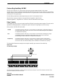
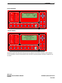
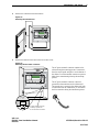
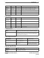
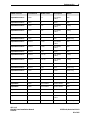
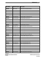
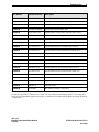
Left-Panel-Indicators
The figure below illustrates left-panel-indicators:
Figure 2-3
Left-Panel-Indicators
Fire
AC Power On
Pre-Alarm
On Test
Panel Sounder
Silenced
Delay Active
More Events
General
Disablement
General Trouble
Power Trouble
Supervisory
NAC Trouble
A
B
C
D
E
F
G
H
I
J
K
L
Key LED Indicator Color
AFire, NAC Output State
- Flashing = NACs Activated
- ON Continuous = NACs silenced
- OFF = Panel and NACs Reset
Red
BAC Power On Green
CPre Alarm Yellow
DOn Test Yellow
EPanel Sounder Silence Yellow
FDelay Active Yellow
GMore Events Yellow
HPoint Bypassed Yellow
IGeneral Trouble Yellow
JPower Trouble Yellow
KSupervisory Yellow
LNAC Trouble Yellow

Overview 2
VES, LLC
Elite-RS Panel Installation Manual VF3529-00, Revision E01.03
H-Series 10 of 145
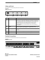
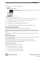
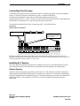
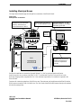
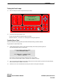
Right-Panel Controls
The figure below illustrates right-panel controls:
Figure 2-4
Right-Panel Controls
More
Fire Events More
Events
EnterExit
1
2
3
4?
A
B
C
D
E
F
G
H
I
Key Name Description
A Keypad number one Navigates menu selections up.
B Keypad number four Navigates menu selections to the left.
C Keypad number three Navigates menu selections down.
D Exit Cancels the current menu selection.
E More Fire Events Displays the number of alarms present
on the Elite-RS Panel and overrides the
display provided by menu navigation.
F Keypad number two Navigates menu selections to the right.
G Keypad question mark Provides a “help screen” for the current
menu display and also displays status.
For example, recommendations are
displayed during alarm or fault conditions.
If a menu function is accessed then help
relating to that function will be displayed.
H Enter Enables the menu selection.
I More Events Displays the number of events present
and overrides menu navigation. Provides
event status for Fire, Pre-Alarm, Trouble,
Disablements and Other.
Page is loading ...
Page is loading ...
Page is loading ...
Page is loading ...
Page is loading ...
Page is loading ...
Page is loading ...
Page is loading ...
Page is loading ...
Page is loading ...
Page is loading ...
Page is loading ...
Page is loading ...
Page is loading ...
Page is loading ...
Page is loading ...
Page is loading ...
Page is loading ...
Page is loading ...
Page is loading ...
Page is loading ...
Page is loading ...
Page is loading ...
Page is loading ...
Page is loading ...
Page is loading ...
Page is loading ...
Page is loading ...
Page is loading ...
Page is loading ...
Page is loading ...
Page is loading ...
Page is loading ...
Page is loading ...
Page is loading ...
Page is loading ...
Page is loading ...
Page is loading ...
Page is loading ...
Page is loading ...
Page is loading ...
Page is loading ...
Page is loading ...
Page is loading ...
Page is loading ...
Page is loading ...
Page is loading ...
Page is loading ...
Page is loading ...
Page is loading ...
Page is loading ...
Page is loading ...
Page is loading ...
Page is loading ...
Page is loading ...
Page is loading ...
Page is loading ...
Page is loading ...
Page is loading ...
Page is loading ...
Page is loading ...
Page is loading ...
Page is loading ...
Page is loading ...
Page is loading ...
Page is loading ...
Page is loading ...
Page is loading ...
Page is loading ...
Page is loading ...
Page is loading ...
Page is loading ...
Page is loading ...
Page is loading ...
Page is loading ...
Page is loading ...
Page is loading ...
Page is loading ...
Page is loading ...
Page is loading ...
Page is loading ...
Page is loading ...
Page is loading ...
Page is loading ...
Page is loading ...
Page is loading ...
Page is loading ...
Page is loading ...
Page is loading ...
Page is loading ...
Page is loading ...
Page is loading ...
Page is loading ...
Page is loading ...
Page is loading ...
Page is loading ...
Page is loading ...
Page is loading ...
Page is loading ...
Page is loading ...
Page is loading ...
Page is loading ...
Page is loading ...
Page is loading ...
Page is loading ...
Page is loading ...
Page is loading ...
Page is loading ...
Page is loading ...
Page is loading ...
Page is loading ...
Page is loading ...
Page is loading ...
Page is loading ...
Page is loading ...
Page is loading ...
Page is loading ...
Page is loading ...
Page is loading ...
Page is loading ...
Page is loading ...
Page is loading ...
Page is loading ...
Page is loading ...
Page is loading ...
Page is loading ...
Page is loading ...
Page is loading ...
Page is loading ...
Page is loading ...
Page is loading ...
Page is loading ...
Page is loading ...
Page is loading ...
Page is loading ...
Page is loading ...
-
 1
1
-
 2
2
-
 3
3
-
 4
4
-
 5
5
-
 6
6
-
 7
7
-
 8
8
-
 9
9
-
 10
10
-
 11
11
-
 12
12
-
 13
13
-
 14
14
-
 15
15
-
 16
16
-
 17
17
-
 18
18
-
 19
19
-
 20
20
-
 21
21
-
 22
22
-
 23
23
-
 24
24
-
 25
25
-
 26
26
-
 27
27
-
 28
28
-
 29
29
-
 30
30
-
 31
31
-
 32
32
-
 33
33
-
 34
34
-
 35
35
-
 36
36
-
 37
37
-
 38
38
-
 39
39
-
 40
40
-
 41
41
-
 42
42
-
 43
43
-
 44
44
-
 45
45
-
 46
46
-
 47
47
-
 48
48
-
 49
49
-
 50
50
-
 51
51
-
 52
52
-
 53
53
-
 54
54
-
 55
55
-
 56
56
-
 57
57
-
 58
58
-
 59
59
-
 60
60
-
 61
61
-
 62
62
-
 63
63
-
 64
64
-
 65
65
-
 66
66
-
 67
67
-
 68
68
-
 69
69
-
 70
70
-
 71
71
-
 72
72
-
 73
73
-
 74
74
-
 75
75
-
 76
76
-
 77
77
-
 78
78
-
 79
79
-
 80
80
-
 81
81
-
 82
82
-
 83
83
-
 84
84
-
 85
85
-
 86
86
-
 87
87
-
 88
88
-
 89
89
-
 90
90
-
 91
91
-
 92
92
-
 93
93
-
 94
94
-
 95
95
-
 96
96
-
 97
97
-
 98
98
-
 99
99
-
 100
100
-
 101
101
-
 102
102
-
 103
103
-
 104
104
-
 105
105
-
 106
106
-
 107
107
-
 108
108
-
 109
109
-
 110
110
-
 111
111
-
 112
112
-
 113
113
-
 114
114
-
 115
115
-
 116
116
-
 117
117
-
 118
118
-
 119
119
-
 120
120
-
 121
121
-
 122
122
-
 123
123
-
 124
124
-
 125
125
-
 126
126
-
 127
127
-
 128
128
-
 129
129
-
 130
130
-
 131
131
-
 132
132
-
 133
133
-
 134
134
-
 135
135
-
 136
136
-
 137
137
-
 138
138
-
 139
139
-
 140
140
-
 141
141
-
 142
142
-
 143
143
-
 144
144
-
 145
145
-
 146
146
-
 147
147
-
 148
148
-
 149
149
-
 150
150
-
 151
151
-
 152
152
-
 153
153
-
 154
154
-
 155
155
-
 156
156


VES Elite-RS H-Series Installation guide
- Category
- Fire protection
- Type
- Installation guide
Ask a question and I''ll find the answer in the document
Finding information in a document is now easier with AI
Related papers

Other documents
-
 SILENT KNIGHT SK-2-E Fire Alarm Control Panel User manual
-
Notifier Series CH Chimes and Chime Strobes Owner's manual
-
Command access “DL20” Door Loops User manual
-
Hochiki 4 Channel NAC Module (5793) Information Guide
-
 Digital Monitoring Products 505-12L/505-12A POWER SUPPLY Product information
-
Potter PAD100-SB Addressable Sounder Base Owner's manual
-
Honeywell HPF24S6 Installation guide
-
ELK ELK-WK1 Operating instructions
-
Potter MOM-4 User manual
-
DMTech Fire alarm panels FP9000L Instructions Manual

