MI00620-1-EN INSTALLATION MANUAL 3/4
INSTALLATION REGULATIONS
ModBUS CONNECTION RULES
1) Install the modules in the DIN rail (120 max)
2) Connect the remote modules using cables of an appropriate length. The following table shows cable length data:
-Bus length: maximum length of the Modbus network according to the Baud Rate. This is the length of the cables that connect the two
farthest modules.
-Derivation length: maximum length of a derivation 2 m.
For maximum performance, it is recommended to use special shielded cables, designed specically for data communication.
The module has been designed for vertical installation on a DIN 46277 rail. For optimal operation and long life, adequate
ventilation must be provided. Avoid positioning ducting or other objects that obstruct the ventilation slots. Avoid mount-
ing modules over heat-generating equipment. Installation in the bottom part of the electrical panel is recommended.
ATTENTION: These are open type devices intended for installation in a nal casing/panel that offers mechanical protec-
tion and protection against the spread of re.
CERTIFICATIONS
POWER SUPPLY 11 ÷ 40Vdc; 50 ÷ 60Hz; Max absorption: 6 W
ENVIRONMENTAL
CONDITIONS
Operating temperature:
from -25°C to +65°C; Humidity: 10% ÷ 90% non condensing.
Storage temperature: from -30°C to +80°C; Degree of protection: IP20
ASSEMBLY 35mm DIN rail IEC EN60715
CONNECTIONS Removable 3.5 mm pitch terminal block, 1.5 mm2 max cable section
PROCESSOR ARM 32 bit
MEMORY 512MB RAM and ≥ 4GB Flash; PUSH-PUSH type slot for micro SD
FEATURES Integrated Web Server and update via Web Server
COMMUNICATION
PORTS
COM1: RS232 / RS485 (on terminals), COM2: RS485 (on terminals or IDC10)
COM4: RS485 (on terminals); maximum Baud rate 115kbps; minimum 200 bps; USB HOST type A
ETH1 and ETH2 Fast Ethernet RJ45 10/100Mbps, Maximum connection distance: 100 m
CAN (on terminals).
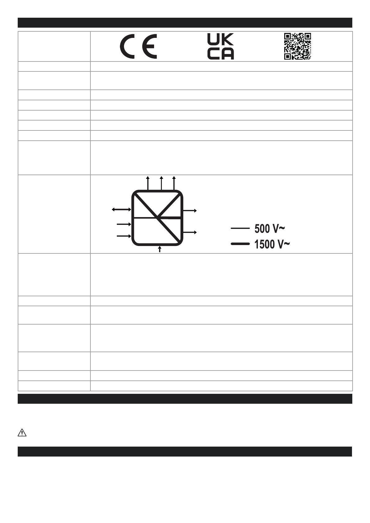
ISOLATION
DIGITAL
INPUTS
OUTPUTS
Number of inputs: 6 max.; Number of outputs: 6 max.;
Absorbed current: 3mA @ 12Vdc, 5mA @ 24Vdc.
Voltage OFF<4V, ON>8V MAX. current (Vout+) 50mA
Voltage (Vext+): 10
÷ 28Vdc. MAX. current: 200 mA per channel
Protect the outputs using a 1.5A fuse as shown in the wiring diagrams
ANALOGUE INPUTS Voltage 0 ÷ 30Vdc, impedance 200kΩ Current 0 ÷ 25mA, impedance ~ 50Ω
AUXILIARY
VOLTAGE
OUTPUT V AUX: 12Vdc; Max. 50 mA
4G MODEM FREQUENCIES
Global coverage Model 4G/LTE
LTE-FDD: B1/B2/B3/B4/B5/B7/B8/B12/B13/B18/ B19/B20/B25/B26/B28
LTE-TDD: B38/B39/B40/ B41; WCDMA: B1/B2/B4/B5/B6/B8/B19/GSM: B2/B3/B5/B
OUTPUT POWER
GSM900: 32.75dBm, DCS1800: 29.07dBm, WCDMA: 23.13dBm, 23.27 dBm, LTE: 23.1dBm,
23.2dBm, 21.7dBm, 23.19dBm, 23.14dBm, 23.7dBm, 23.39dBm.
GNSS
GPS / GLONASS / BeiDou (compass) / Galileo / QZSS
SIM CARD SLOT
Push-push type for mini SIM card 15 X 25 mm
Comm.
Power
Supply
USB
Intput
Output
Analog
Input Comm.
ETH
LAN
ETH
WAN
DI / DO Comm.
USBRS485
RS485
RS232
TECHNICAL SPECIFICATIONS


