MI00582-0-EN INSTALLATION MANUAL 2/6
MODULE LAYOUT
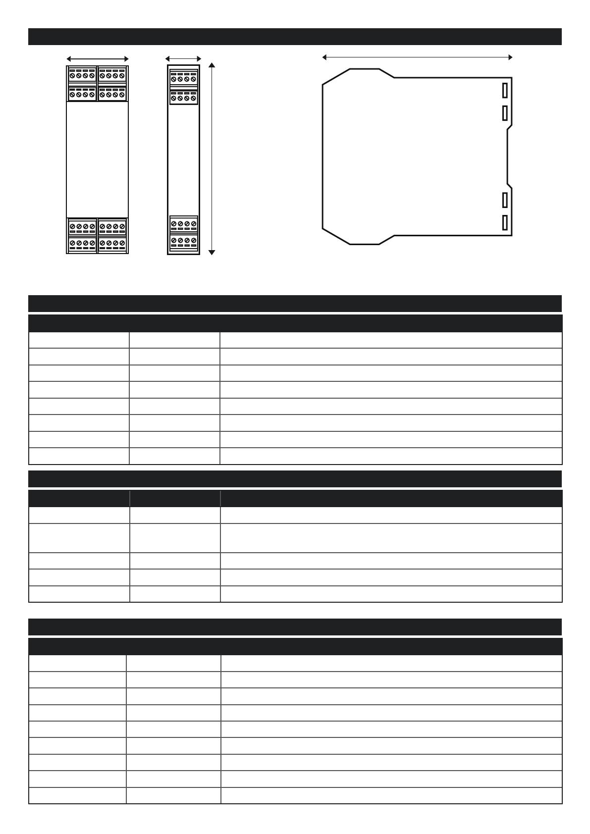
17.5 mm 111 mm
102.5 mm
35 mm
LED SIGNALS ON THE FRONT PANEL (ZE-4DI-2AI-2DO)
LED STATUS MEANING
IP / PWR ON Module powered IP address acquired
IP / PWR Flashing Module powered Waiting for IP address from the DHCP server
Tx/Rx Flashing Data transmission and reception on at least one Modbus port
ETH TRF Flashing Packet transmission on Ethernet port
ETH LNK ON Ethernet port connected
DI1, DI2, DI3, DI4 On / Off Status of digital input 1, 2, 3, 4
DO1, DO2 On / Off Status of output 1, 2
FAIL Flashing Outputs in fail condition
LED SIGNALS ON THE FRONT PANEL (Z-4DI-2AI-2DO)
LED STATUS MEANING
PWR ON Module powered
Tx/Rx Flashing Data transmission and reception on at least one Modbus port:
COM 1 port, COM 2 port
DI1, DI2, DI3, DI4 On / Off Status of digital input 1, 2, 3, 4
DO1, DO2 On / Off Status of output 1, 2
FAIL Flashing Outputs in fail condition
LED SIGNALS ON THE FRONT PANEL (ZE-2AI)
LED STATUS MEANING
IP / PWR ON Module powered and IP address acquired
IP / PWR Flashing Module powered Waiting for IP address from the DHCP server
FAIL ON At least one of the two analogue inputs is out of scale (underscale-overscale)
ETH TRF Flashing Packet transmission on Ethernet port
ETH LNK ON Ethernet port connected
Tx1 Flashing Modbus packet transmission from device to COM 1 port
Rx1 Flashing Modbus packet reception on COM 1 port
Tx2 Flashing Modbus packet transmission from device to COM 2 port
Rx2 Flashing Modbus packet reception on COM 2 port
Single module dimensions LxHxD: 17.5 x 102.5 x 111 mm; Weight: 110 g; Enclosure: PA6, black
Double module dimensions LxHxD: 35 x 102.5 x 111 mm; Weight: 110 g; Enclosure: PA6, black
ZE-4DI-2AI-2DO ZE-2AI
Z-4DI-2AI-2DO


