Page is loading ...

user manual
ARTiGO-A1100
Barebone System with
EPIA-P820 Embedded Board
Revision
1.0
4
10
4
-
11
2
3
2010
-
1
05
6

II
Copyright and Trademarks
Copyright © 2010 VIA Technologies Incorporated. All rights reserved.
No part of this document may be reproduced, transmitted, transcribed, stored in a
retrieval system, or translated into any language, in any form or by any means, electronic,
mechanical, magnetic, optical, chemical, manual or otherwise without the prior written
permission of VIA Technologies, Incorporated.
All trademarks are the property of their respective holders.
PS/2 is a registered trademark of IBM Corporation.
Disclaimer
No license is granted, implied or otherwise, under any patent or patent rights of VIA
Technologies. VIA Technologies makes no warranties, implied or otherwise, in regard to
this document and to the products described in this document. The information provided
in this document is believed to be accurate and reliable as of the publication date of this
document. However, VIA Technologies assumes no responsibility for the use or misuse of
the information in this document and for any patent infringements that may arise from the
use of this document. The information and product specifications within this document are
subject to change at any time, without notice and without obligation to notify any person
of such change.
Regulatory Compliance
FCC-A Radio Frequency Interference Statement
This equipment has been tested and found to comply with the limits for a class B digital
device, pursuant to part 15 of the FCC rules. These limits are designed to provide
reasonable protection against harmful interference when the equipment is operated in a
commercial environment. This equipment generates, uses, and can radiate radio
frequency energy and, if not installed and used in accordance with the instruction manual,
may cause harmful interference to radio communications. Operation of this equipment in a
residential area is likely to cause harmful interference, in which case the user will be
required to correct the interference at his personal expense.
Notice 1
The changes or modifications not expressly approved by the party responsible for
compliance could void the user's authority to operate the equipment.
Notice 2
Shielded interface cables and A.C. power cord, if any, must be used in order to comply
with the emission limits.
Battery Recycling and Disposal
Only use the appropriate battery specified for this product.
Do not re-use, recharge, or reheat an old battery.
Do not attempt to force open the battery.
Do not discard used batteries with regular trash.
Discard used batteries according to local regulations.
Tested To Comply
With FCC Standards
FOR HOME OR OFFICE USE

III
Safety Precautions
Do’s
o Always read the safety instructions carefully.
o Keep this User's Manual for future reference.
o All cautions and warnings on the equipment should be
noted.
o Keep this equipment away from humidity.
o Lay this equipment on a reliable flat surface before setting
it up.
o Make sure the voltage of the power source and adjust
properly 110/220V before connecting the equipment to the
power inlet.
o Place the power cord in such a way that people cannot
step on it.
o Always unplug the power cord before inserting any add-on
card or module.
o If any of the following situations arises, get the equipment
checked by authorized service personnel:
o The power cord or plug is damaged.
o Liquid has penetrated into the equipment.
o The equipment has been exposed to moisture.
o The equipment has not worked well or you cannot
get it work according to User's Manual.
o The equipment has dropped and damaged.
o The equipment has obvious sign of breakage.
Don’ts
o Do not leave this equipment in an environment
unconditioned or in a storage temperature above 60°C
(140°F). The equipment may be damaged.
o Do not leave this equipment in direct sunlight.
o Never pour any liquid into the opening. Liquid can cause
damage or electrical shock.
o Do not place anything over the power cord.
o Do not cover the ventilation holes. The openings on the
enclosure protect the equipment from overheating

IV
Box Contents
1 x ARTiGO-A1100 system
1 x "Drivers and Utility" CD disc
1 x AC-to-DC adapter, DC 12V/5A, 60W
1 x Power cable, 180 cm, USA type

V
Ordering Information
Model Number Description
ATG-1100-1N12A1 VIA Nano™ 1.2GHz Processor based
Embedded System, with 1 x VGA, 1 x
HDMI, HD Audio (Line-in, Line-out and Mic-
in), 1 x GigaLAN, 4 x USB 2.0 1 x USB
device, DC-In 12V
Optional Accessories
Power Cord
99G33-02034C Power cord with PSE mark, 180 cm
for Japan market
99G33-02033C Power cord, 180 cm, Europe type
99G33-02031C Power cord, 180 cm, UK type
SD Card Reader
EMIO-5130-00A1 1 x slot SD card reader
WLAN Module
EMIO-1530-80A1 802.11 b/g Wireless LAN USB Module for
USA
EMIO-1530-90A1 802.11 b/g Wireless LAN USB Module for
Europe

VI
T
ABLE OF
C
ONTENTS
1 Product Overview............................................................................................... 1
Key Features........................................................................................................... 2
Specifications ......................................................................................................... 4
ARTiGO-A1100 Dimensions........................................................................... 7
2 Front, Rear and Side I/O Pin Descriptions and Functionality........ 9
Front I/O Layout ................................................................................................10
Rear I/O Layout ..................................................................................................10
Side I/O Layout...................................................................................................10
I/O Pin Description ...........................................................................................11
Power Button.................................................................................................11
LED Indicators (Power LED and HDD LED)...................................11
USB device port.............................................................................................11
USB 2.0 ports..................................................................................................11
Audio Ports (Line-out, Line-in and Mic-in)........................................12
VGA Port ..........................................................................................................12
HDMI Port ........................................................................................................13
LAN Port ...........................................................................................................13
Power Input (DC-In) Port..........................................................................13
3 Basic installation .................................................................................................15
Installing the memory .....................................................................................16
Opening the Top Cover Chassis................................................................19
Installing the SATA 2.5” Hard Disk ............................................................20
Installing the SD Card Reader .....................................................................24
Installing the WLAN kit ...................................................................................28
Installing VESA Mount Bracket ...................................................................32
4 BIOS Setup............................................................................................................35
Entering the BIOS Setup Menu..................................................................36
Control Keys .........................................................................................................36
Getting Help ........................................................................................................37
Main Menu ...........................................................................................................38
AMIBIOS............................................................................................................38
Processor ..........................................................................................................38
System Memory.............................................................................................38
System Time ....................................................................................................38
System Date ....................................................................................................38
Advanced Settings............................................................................................39
CPU Configuration ......................................................................................39

VII
IDE Configuration ........................................................................................39
ACPI Configuration .....................................................................................39
APM Configuration .....................................................................................39
Spread Spectrum Configuration...........................................................39
USB Configuration.......................................................................................39
CPU Configuration ...........................................................................................40
CMPXCHG8B instruction support........................................................40
Nano CPU Thermal Monitor Adjust....................................................40
IDE Configuration .............................................................................................41
Parallel ATA IDE Controller......................................................................41
Hard Disk Write Protect ............................................................................41
IDE Detect Time Out (Sec).......................................................................41
ATA(PI) 80Pin Cable Detection .............................................................41
IDE Drives..............................................................................................................42
Primary IDE Master ......................................................................................42
Primary IDE Slave (SATA Device)..........................................................42
Type.....................................................................................................................43
LBA/Large Mode..........................................................................................43
Block (Multi-Sector Transfer)....................................................................43
PIO Mode.........................................................................................................43
DMA Mode .....................................................................................................43
S.M.A.R.T............................................................................................................43
32Bit Data Transfer......................................................................................43
ACPI Settings........................................................................................................44
General ACPI Configuration...................................................................44
Advanced ACPI Configuration..............................................................44
Chipset ACPI Configuration ....................................................................44
General ACPI Configuration ........................................................................45
Suspend Mode ..............................................................................................45
Repost Video on S3 Resume ..................................................................45
Advanced ACPI Configuration ...................................................................46
ACPI Version Features ...............................................................................46
ACPI APIC Support.......................................................................................46
AMI OEMB Table..........................................................................................46
Headless Mode..............................................................................................46
Chipset ACPI Configuration .........................................................................47
USB Device Wakeup Function..............................................................47
APM Configuration...........................................................................................48
Power Management / APM ...................................................................48
Power Button Mode...................................................................................48
Suspend Power Saving Type..................................................................48
Restore on AC / Power Loss...................................................................48
Manual Throttle Ratio.................................................................................48
System Thermal .............................................................................................49

VIII
Standby Time Out........................................................................................49
Suspend Time Out.......................................................................................49
Hard Disk Time Out (Minute).................................................................49
Green PC Monitor Power State.............................................................49
Video Power Down Mode......................................................................49
Hard Disk Power Down Mode .............................................................49
Display Activity...............................................................................................49
Monitor IRQ3~15.........................................................................................49
Resume on Ring............................................................................................50
Resume on PME#.........................................................................................50
Resume On PS/2 KBC ................................................................................50
Wake-up Key ..................................................................................................50
Resume on PS/2 Mouse............................................................................50
Resume on RTC Alarm...............................................................................50
Spread Spectrum Configuration................................................................51
Spread Spectrum Configuration...........................................................51
USB Configuration ............................................................................................52
USB 1.1 Ports Configuration ...................................................................52
USB 2.0 Ports Enable ..................................................................................52
USB Device Mode Enable........................................................................52
Legacy USB Support...................................................................................52
USB 2.0 Controller Mode .........................................................................52
BIOS EHCI Hand-Off ...................................................................................52
Advanced PCI/PnP Settings..........................................................................53
Clear NVRAM .................................................................................................53
Plug & Play O/S.............................................................................................53
PCI Latency Timer.........................................................................................53
Allocate IRQ to PCI VGA...........................................................................53
Palette Snooping ..........................................................................................53
PCI IDE BusMaster........................................................................................54
Off Board PCI/ISA IDE Card ....................................................................54
IRQ3~15 ...........................................................................................................54
DMA Channel 0~7 .....................................................................................54
Reserved Memory Size...............................................................................54
Boot Settings........................................................................................................55
Boot Settings Configuration....................................................................55
Boot Device Priority.....................................................................................55
Boot Settings Configuration.........................................................................56
Quick Boot.......................................................................................................56
Display Logo...................................................................................................56
AddOn ROM Display Mode....................................................................56
Bootup Num-Lock .......................................................................................56
PS/2 Mouse Support...................................................................................56
Wait For ‘F1’ If Error....................................................................................56

IX
Hit ‘DEL’ Message Display........................................................................56
Interrupt 19 Capture...................................................................................57
Boot Device Priority ..........................................................................................58
1st Boot Device .............................................................................................58
Security Settings..................................................................................................59
Change Supervisor Password................................................................59
Change User Password ............................................................................59
Boot Sector Virus Protection...................................................................59
Advanced Chipset Settings...........................................................................60
North Bridge VIA VX855 Configuration...........................................60
South Bridge VIA VX855 Configuration...........................................60
North Bridge VIA VX855 Configuration................................................61
Software Reset E2 Issue.............................................................................61
Change DCLK using RDCKM .................................................................61
Dynamic CKE..................................................................................................61
NB Performance Register .........................................................................61
NB Energy Saving Register......................................................................61
OnChip VGA Configuration........................................................................62
VGA Frame Buffer Size..............................................................................62
CPU Direct Access Frame Buffer ..........................................................62
Select Display Device..................................................................................62
Panel Type .......................................................................................................62
Dithering ..........................................................................................................62
Backlight Control ..........................................................................................62
South Bridge VIA VX855 Configuration................................................63
Parallel Channel Enable ............................................................................63
ISA Master Support......................................................................................63
High Definition Audio................................................................................63
Enable Embedded COM..........................................................................63
PCI Debug Master Mode..........................................................................63
SMBus Multi-Master.....................................................................................63
PCI VCC33 Leakage Patch.......................................................................63
PCI Delay Transaction ................................................................................64
WATCH-DOG ................................................................................................64
Exit Options ..........................................................................................................65
Save Changes and Exit..............................................................................65
Discard Changes and Exit........................................................................65
Discard Changes ..........................................................................................65
Load Optimal Defaults...............................................................................65
5 Driver Installation...............................................................................................67
Driver Utilities.......................................................................................................68
Getting Started ..............................................................................................68
Running the Driver Utilities CD .............................................................68
CD Content ..........................................................................................................69

1
1
Product Overview

2
The ARTiGO-A1100 is an ultra compact embedded system. Its
based on the VIA EPIA-P820 Pico-ITX form factor board and
powered by high performance VIA Nano 1.2 GHz processor. The
ARTiGO-A1100 chassis is designed with dual-sided I/O access
plates for easy integration.
The mechanical parts in the ARTiGO-A1100 consist of a system
chassis, removable top cover and front faceplate. The ARTiGO-
A1100 comes with built-in SATA data and power cables for 2.5”
SATA hard disks. The ARTiGO-A1100 is also available with an
optional SD card reader and WLAN (wireless LAN) module.
KEY FEATURES
U
UU
Ultra compact chassis for the
ltra compact chassis for the ltra compact chassis for the
ltra compact chassis for the EPIA
EPIAEPIA
EPIA-
--
-P820
P820P820
P820
The ARTiGO-A1100 houses the VIA EPIA-P820 Pico-ITX form factor
board with a maximum height of 56 mm, width of 99 mm and
length of 146 mm. The ARTiGO-A1100 chassis is rugged
aluminum case, design to ensure maximum reliability.
S
SS
Small and
mall and mall and
mall and s
ss
stylish design
tylish designtylish design
tylish design
The ARTiGO-A1100 housing is composed of three mechanical
parts: the chassis, removable top cover and front faceplate. Its
space saving design enables it to be installed in space critical
environments.
Optimized integration with front and rear I/O access
Optimized integration with front and rear I/O accessOptimized integration with front and rear I/O access
Optimized integration with front and rear I/O access
Front and rear I/O access enables the ARTiGO-A1100 to easily
supports various applications as well as for easy integration and
quick setup.
Quick Data Transmission by USB
Quick Data Transmission by USB Quick Data Transmission by USB
Quick Data Transmission by USB d
dd
device port
evice portevice port
evice port
The ARTiGO-A1100 comes with one USB device port that allows
ARTiGO-A1100 as a USB Client device for user friendly and quick
data transfer to another computer.
Display Acceleration
Display AccelerationDisplay Acceleration
Display Acceleration
The ARTiGO-A1100 supports hardware acceleration of MPEG-2/4,
WMV9 and H.264 for 1080p full HD display
Shock Resistant
Shock ResistantShock Resistant
Shock Resistant
The ARTiGO-A1100 is shock resistant to 20G for maximum
reliability.

3
Networking
Networking Networking
Networking support
supportsupport
support
The ARTiGO-A1100 is equipped with an RJ-45 port that supports
Gigabit Ethernet. The ARTiGO-A1100 also has a WLAN module
option that gives the ARTiGO-A1100 freedom of WiFi access.
Embedded OS
Embedded OS Embedded OS
Embedded OS r
rr
ready
eadyeady
eady
The ARTiGO-A1100 is 100% compatible with several operating
systems including Microsoft Widows XP, Windows XP Embedded,
and Ubuntu Linux. ARTiGO-A1100 is also well suited to the
newest Microsoft operating system which is the Windows 7.

4
SPECIFICATIONS
Processor Core
Logic System
CPU
CPUCPU
CPU
• VIA Nano 1.2 GHz processor
• NanoBGA2 package
• 800 MHz Front Side Bus speed
• 1 MB L2 Cache memory
System Chipset
System ChipsetSystem Chipset
System Chipset
• VIA VX855 Unified Digital Media IGP chipset
BIOS
BIOSBIOS
BIOS
• AMI BIOS
• 4Mbit LPC Flash Memory
System Power Management
System Power ManagementSystem Power Management
System Power Management
• Times Power On
• ACPI Supported
System Memory
Technology
TechnologyTechnology
Technology
• One DDR2 533/667/800 MHz SDRAM SODIMM slot
Maximum Capacity
Maximum CapacityMaximum Capacity
Maximum Capacity
• Supports memory sizes up to 2 GB
Graphic
Controller
ControllerController
Controller
• Integrated VIA Chrome9 HCM DX9 3D/2D Graphics and
Video Processor
• Integrated Unified Video Decoding Accelerator for
MPEG-2/4, H.264 and WMV9
Display M
Display MDisplay M
Display Memory
emoryemory
emory
• Optimized Shared Memory Architecture (UMA), supports
up to 256 MB frame buffer using system memory
CRT Interface
CRT InterfaceCRT Interface
CRT Interface
• Supports one VGA connector
• Pixel resolution support up 1920 x 1200
HDMI Interface
HDMI InterfaceHDMI Interface
HDMI Interface
• Supports one HDMI port
Dual Independent
Dual IndependentDual Independent
Dual Independent Display
Display Display
Display
• Supports CRT + HDMI at the same resolutions, pixel
depths, and refresh rates
Gigabit Ethernet
Controller
ControllerController
Controller
• Onboard VIA VT6122 Gigabit Ethernet controllers
Interface
InterfaceInterface
Interface
• One RJ-45 connector
• Supports Wake On LAN (WOL)
Audio
Controller
ControllerController
Controller
• VIA VT1708S High Definition Audio Codec
Interface
InterfaceInterface
Interface
• Support three 3.5Ø Audio jacks (Line-in, Line-out, and Mic-in)

5
USB 2.0
U
UU
USB
SBSB
SB 2.0
2.0 2.0
2.0 ports
ports ports
ports
• Supports four USB 2.0 ports
• Supports one USB device port
Storage
Interface
Hard Disk Drive
Hard Disk DriveHard Disk Drive
Hard Disk Drive
• One 2.5-inch hard disk drive bay supports 2.5-inch SATA
interface HDD and Flash SSD
SD
SDSD
SD
• Reserve space for optional support of one SD card by
EMIO-5130 (optional) SD card reader
System Indicator
Power Status LED
Power Status LEDPower Status LED
Power Status LED
• One green color LED
HDD Activity LED
HDD Activity LEDHDD Activity LED
HDD Activity LED
• One red color LED
Watchdog Timer
Output
OutputOutput
Output
• System reset
Interval
IntervalInterval
Interval
• Programmable 1~255 sec.
I/O connectors
Front I/O
Front I/OFront I/O
Front I/O
• Two USB 2.0 host ports
• One USB device port
• Three 3.5Ø Audio jacks support
• Line-in, Line-out and Mic.-in
Rear
Rear Rear
Rear I/O
I/OI/O
I/O
• One VGA connector (D-Sub 15-pin female connector)
• Two USB 2.0 host ports
• One HDMI connector
• One RJ-45 connector for Gigabit Ethernet connection
Left I/O
Left I/O Left I/O
Left I/O
• One SD slot for SD card (optional)
Power Supply
Power Consumption
Power ConsumptionPower Consumption
Power Consumption
• Typical 12.84W, Maximum 20.72W
Input Voltage
Input VoltageInput Voltage
Input Voltage
• DC 12V Power Input
• Typical Power Input: 12VDC @ 1.07A
Power Input Connector
Power Input ConnectorPower Input Connector
Power Input Connector
• DC Power Input connector by DC Jack connector
Fuse Rating
Fuse RatingFuse Rating
Fuse Rating
• 7A @ 125V

6
Mechanical
Construction
ConstructionConstruction
Construction
• Aluminum Chassis Housing
Mounting
MountingMounting
Mounting
•Optional Wall/VESA dual function mouting bracket
Dimension (W x H x D)
Dimension (W x H x D)Dimension (W x H x D)
Dimension (W x H x D)
• 146 mm x 52 mm x 99 mm
Weight
WeightWeight
Weight
• 0.6 Kg (1.32 lbs)
Environment
Specifications
Operating
OperatingOperating
Operating
Temperature
TemperatureTemperature
Temperature
• 0°C to 45°C
Storage
StorageStorage
Storage
Temperature
TemperatureTemperature
Temperature
• -10°C to 60°C
Operatin
OperatinOperatin
Operating
gg
g
H
HH
Humidity
umidityumidity
umidity
• 0% ~ 90% @ 45°C, relative humidity, non-condensing
Vibration loading during operation
Vibration loading during operationVibration loading during operation
Vibration loading during operation
• 0.6Grms, IEC 60068-2-64, random, 5~500Hz, 1 Oct./min,
1hr/axis
Shock during operation
Shock during operationShock during operation
Shock during operation
• 20G, IEC 60068-2-27, half size, 11ms duration
EMC appr
EMC apprEMC appr
EMC approved
ovedoved
oved
• CE, FCC Class B
Software
Compatibility
Operating System
Operating SystemOperating System
Operating System
• Microsoft Widows XP, Windows 7
• Windows XP Embedded, Ubuntu Linux

7
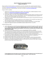
ARTIGO-A1100 DIMENSIONS

8

9
2
Front, Rear and Side
I/O Pin Descriptions
and Functionality

10
FRONT I/O LAYOUT
REAR I/O LAYOUT
SIDE I/O LAYOUT

11
I/O PIN DESCRIPTION
Power Button
The ARTiGO-A1100 comes with a Power On/Off
button, that supports Soft Power-On/Off (Instant
Off or 4-Second Delay) and Suspend.
LED Indicators (Power LED and HDD LED)
There are two LEDs on the front face
plate that indicate the system status: The
Power LED indicates the power status
and flashes in green. The HDD LED
indicates the hard disk status and flashes
in red.
USB device port
The ARTiGO-A1100 provides a USB device port in the front panel for
quick data transfer to another computer.
Pin Signal
1 +5VUSBD
2 USBDP-
3 USBDP+
4 USBID
5 GND
USB 2.0 ports
The ARTiGO-A1100 provides four USB 2.0 ports (two in the front
panel, and two in the rear panel) for Plug & Play and hot
swapping access to external devices. The USB interface complies
with USB UHCI, Rev. 2.0.
Pin Signal
1 VCC
2 USB_P0-
3 USB_P0+
4 GND
/