CAME v6000 Installation guide
- Category
- Garage Door Opener
- Type
- Installation guide

INSTALLATION MANUAL
V6000
OPERATOR
FOR GARAGE DOORS
En
g
lis
h
EN
119EV88EN

Page
2
2 - Manual code:
119EV88EN
119EV88 EN ver.
5
5 09/2013 © CAME cancelli automatici S.p.A. - The data and information provided in this manual are subject to change at any time without prior notice by CAME Cancelli Automatici S.p.A.
Foreword
• This product should only be used for the purpose for which it was explicitly de-
signed. Any other use is considered dangerous. CAME Cancelli Automatici S.p.A.
is not liable for any damage resulting from improper, wrongful or unreasonable
use • Keep these warnings with the installation and use manuals issued with the
automation system.
Before installing
(preliminary check: in case of a negative outcome, do not proceed until you have
complied with the safety requirements)
• Check that the part you intend to automate is in good mechanical condition, bal-
anced and aligned, and that it opens and closes properly. Make sure that proper
mechanical stops are already in place • If the operator will be installed at a height
of less than 2.5 m from the ground or other access level, check if any protection
devices and/or warings are necesary • Read all instructions carefully before per-
forming any operation; incorrect installation may be hazardous and cause damage
to persons and objects. •Any leaves fi tted with pedestrian entrances onto which
an operator will be installed must have a blocking mechanism when the leaf is in
motion • Make sure that the opening of the automated leaf is not an entrapment
hazard as regards any surrounding fi xed parts • Do not mount the operator upside
down or onto any elements that may fold under its weight. If needed, add suitable
reinforcements at the points where it is secured • Do not install onto leaves not on
level ground • Check that any lawn watering devices will not wet the operator from
the bottom up. • Check that the temperature of the place of installation is compliant
to the range defi ned in this manual.
Installation
• Carefully section o the entire site to prevent unauthorised access, especially by
minors and children • Be careful when handling operators that weigh more than 20
kg. In the case, make sure to have all tools for safe handling • All opening controls
(buttons, key switches, magnetic readers, etc..) must be installed at least 1.85 m
from the perimeter of the manoeuvring area, or out of reach from external access
via the operator. Furthermore, direct controls (buttons, touch commands, etc.) must
be installed at a height of at least 1.5 m and must not be accessible to the public •
All ‘hold-to-run’ commands must be placed where the moving gate leaves, transit
areas and driveways are completely visible • If missing, apply a permanent label
that shows the position of the release mechanism • Before delivering to the user,
check that the system is EN 12453 (impact test) standard compliant. Make sure that
the operator has been properly adjusted and that the safety and protection devices
as well as the manual release are working properly • Where necessary and in plain
sight, apply the Warning Signs (e.g. gate plate)
Special instructions and advice for users
• Keep the gate’s area of operation clean and clear of any obstacles. Check that
there is no vegetation in the area of operation of the photocells and that there are
no obstacles in the operator's area of operation • Do not allow children to play with
the fi xed control devices, or to remain within the gate’s area of operation. Keep any
remote control devices (i.e. transmitters) or any control devices away from children
as well, to prevent the operator from being activated accidentally •The operator is
not designed to be used by persons (including children) whose physical, sensorial
or mental capacities are limited, or who are lacking in experience or knowledge,
unless said persons can be supervised or given instructions regarding using the
operator by a person responsible for their safety • Frequently check the system, to
see whether any anomalies or signs of wear and tear appear on the moving parts,
on the component parts, on the securing points, on the cables and any accessible
connections. Keep any joints (i.e. hinges) lubricated and clean, and do the same
where friction may occur (i.e. slide rails) • Perform functional tests on photocells
and sensitive edges every six months. To check that the photocells work, pass an
object in front of them during closing. If the operator reverses the direction of move-
ment or comes to a halt, the photocells work correctly. This is the only maintenance
operation that must be carried out while the operator is live. Ensure that the glass
on the photocells is kept clean (use a cloth slightly moistened with water; do not
use solvents or any other chemicals as these could damage the devices) • If the
system requires repairs or modifi cations, release the operator and do not use it until
safety conditions have been restored • Cut o the power supply before releasing the
operator for manual openings and before any other operation, to prevent dangerous
situations. Read the instructions • If the power cable is damaged, it must be re-
placed by the manufacturer or the technical assistance service or by a person with a
similar qualifi cation so as to prevent any risks • It is STRICTLY FORBIDDEN for users
to perform OPERATIONS THEY ARE NOT EXPLICITLY REQUIRED AND ASKED to do in
the manuals. For repairs, adjustments and extraordinary maintenance, CONTACT
THE SPECIALIST TECHNICAL SERVICE CENTRE • On the periodic maintenance log,
note down the checks you have done.
Special instructions and advice for all
• Avoid working near the hinges or moving mechanical parts • Stay clear of the
gate’s area of operation when in motion • Do not resist the direction of movement
of the gate; this may present a safety hazard • At all times be extremely careful
about dangerous points that must be indicated by proper pictograms and/or black
and yellow stripes • When using a selector or command in ‘hold-to-run’ mode, keep
checking that there are no people in the area of operation of the moving parts. Do
this until you release the command • The gate may move at any time without warn-
ing • Always cut the power when cleaning or performing maintenance.
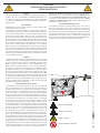
CAUTION!
important personal safety instructions:
READ CAREFULLY!
Danger of hand crushing
Danger of foot crushing
Danger - live parts
No transit during the manoeuvre

2
1
3
5
7
8
6
4
9 10 11 12 13 14
15
Page
3
3 - Manual code:
119EV88EN
119EV88 EN ver.
5
5 09/2013 © CAME cancelli automatici S.p.A. - The data and information provided in this manual are subject to change at any time without prior notice by CAME Cancelli Automatici S.p.A.
KEY
This symbol indicates parts to read carefully.
This symbol indicates parts about safety.
This symbol tells you what to say to the end users.
REGULATORY REFERENCES
Came Cancelli Automatici is a company with an ISO 9001-certified company quality management system and an ISO 14001-certified environmental management system.
The product in question complies with the regulations referred to in the declaration of conformity.
DESCRIPTION
This product complies with the current safety regulations in force.
The operator comprises a gearmotor, an electronic circuit board with transformer, a sliding guide system with chain or belt drive, a motion transmission arm and an ABS cover
with a display for programming keyboard and LED courtesy lamp.
Intended use
The V6000 operator has been designed to automate overhead and sectional doors for use in homes and apartment blocks.
Any installation and operation that differs from what is set out in this manual is prohibited.
Limits of use
Type V6000
Max height of canopy overhead door (m) 2.4
Max height of spring-balanced overhead door (m) 3.25
Max height for sectional doors (m) 3.20
Technical data
Type V6000
Protection rating (IP) 40
Power supply (V - 50/60 Hz) 230 AC
Motor
power supply (V)
24 DC
Absorption in Standby (W): 7
Max power of accessories (W) 35
Power rating (W) 100
Opening speed (m/min) 6
Traction force (N) 600
Operating temperature (°C) -20 - +55
Insulation class
Weight (kg) 4.9
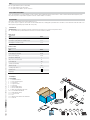
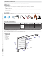
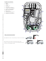
Packing list
1. 1 x Operator
2. 1 x Installation manual
3. 2 x pierced mounting plates
4. 1 x Curved lever
5. 2 x support brackets
6. 3 x U-brackets
7. 1 x Rail mounting bracket
8. 1 x Door mounting bracket
9. 8 x M16 Self-tapping hex head screws
10. 1 x Screw with hex nut M6x80
11. 1 x Shaft adapter (Ø8x25)
12. 1 x Cotter Pin 3x20
13. 1 x Pin
14. 4 x M6x80 Screws with hex nut and washer
15. 1 x Slide rail

210
115
365
10
9
6
7
8
1
4
2
3
5
Page
4
4 - Manual code:
119EV88EN
119EV88 EN ver.
5
5 09/2013 © CAME cancelli automatici S.p.A. - The data and information provided in this manual are subject to change at any time without prior notice by CAME Cancelli Automatici S.p.A.
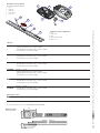
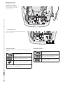
Operator
1. Cover
2. Gearmotor
3. Transformer
4. Control board
5. Power cord
Packing list of pre-assembled rail
6. Rail
7. Chain or belt
8. Block
9. In-line transmission arm
10. Release cord
Description of the components
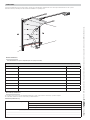
Dimensions (mm)
Slide rail
001V06001
Chain rail L = 3,02 m.
- Canopy overhead doors up to 2.40 m in height;
- Spring-balanced overhead doors up to 2.25 m in height;
- Sectional doors* up to 2.20 m in height.
001V06002 Chain rail L = 3,52 m.
- Spring-balanced overhead doors up to 2.75 m in height;
- Sectional doors* up to 2.70 m in height.
001V06003 Chain rail L = 4,02 m.
- Spring-balanced overhead doors up to 3.25 m in height;
- Sectional doors* up to 3.20 m in height.
001V06005 Belt rail L = 3,02 m.
- Canopy overhead doors up to 2.40 m in height;
- Spring-balanced overhead doors up to 2.25 m in height;
- Sectional doors* up to 2.20 m in height.
001
001V06006 Belt rail L = 3,52 m.
- Spring-balanced overhead doors up to 2.75 m in height;
- Sectional doors* up to 2.70 m in height.
001V06007
Belt rail L = 4,02 m.
- Spring-balanced overhead doors up to 3.25 m in height;
- Sectional doors* up to 3.20 m in height.
Optional Accessories
001
001V201
Transmission arm for canopy overhead doors
001V121
Cord release device to be applied to the handle
For sectional doors, see the section EXAMPLES OF APPLICATION
3020 min ÷ 4020 max

RX
TX
6
1
5
7
6
2
3
4
8
Page
5
5 - Manual code:
119EV88EN
119EV88 EN ver.
5
5 09/2013 © CAME cancelli automatici S.p.A. - The data and information provided in this manual are subject to change at any time without prior notice by CAME Cancelli Automatici S.p.A.
GENERAL INSTALLATION INSTRUCTIONS
Installation must be carried out by qualified and experienced personnel in compliance with applicable regulations.
Preliminary checks
Before starting installation:
• Provide a suitable single-pole disconnection device, with a maximum of 3 mm between the contacts, to disconnect the power supply;
• Prepare suitable piping and ducts for routing the electrical cables, ensuring protection against mechanical damage;
•
Make sure that any connections within the container (made to ensure the continuity of the protection circuit) are fitted with additional insulation compared to the
other internal conductor parts;
• Check that the door is well-balanced. If halted at any intermediate point, it must maintain the position;
• If there is a pedestrian opening in the door, a safety switch must be added, connected to the STOP input, in order to prevent the operator from being operated when the
pedestrian door is open.
Tools and materials
Make sure you have all the tools and materials you will need for the installation at hand to work in total safety and compliance with current standards and regulations. The
figure shows some examples of installer’s tools.
Types of cables and minimum thicknesses
Connection Cable type
Cable length
1 < 10 m
Cable length
10 < 20 m
Cable length
20 < 30 m
Power supply
FROR CEI
20-22
IEC EN
50267-2-1
4G x 1.5 mm
2
4G x 2.5 mm
2
4G x 4 mm
2
Photocell transmitters 2 x 0.5 mm
2
2 x 0.5 mm
2
2 x 0.5 mm
2
Photocell receivers 4 x 0.5 mm
2
4 x 0.5 mm
2
4 x 0.5 mm
2
Control devices 2 x 0.5 mm
2
2 x 0.5 mm
2
2 x 0.5 mm
2
Antenna
connection RG58 max. 10 m
If the cables differ in length from what is shown in the table, the cable cross-section is determined according to the actual current draw of the devices connected and
according to the provisions of the IEC EN 60204-1 standard.
For connections that require several, sequential loads, the sizes given on the table must be re-evaluated based on actual power draw and distances. When connecting products
that are not specified in this manual, please refer to the documentation provided with said products.
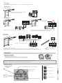
Example of a system
1. Operator with receiver
2. Slide rail
3. Release device
4. Transmission arm
5. Key selector
6. Photocells
7. Pushbutton panel
8. Sensitive edge

(
(
(
H - 100 mm
H
10 ÷ 20 mm
V201
?
20 ÷ 30 mm
max 330 mm
M6x80
M6
Page
6
6 - Manual code:
119EV88EN
119EV88 EN ver.
5
5 09/2013 © CAME cancelli automatici S.p.A. - The data and information provided in this manual are subject to change at any time without prior notice by CAME Cancelli Automatici S.p.A.
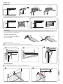
Examples of use
* sectional door
with single rail
* sectional door
with double rail
CANOPY OVERHEAD DOORS, with partially retracting movement.
SPRING-BALANCED OVERHEAD DOOR,, with fully retracting movement
SECTIONAL DOOR
Securing the slide rail
Secure the slide rail to the centre of the door compartment using suitable screws.
Lift up the guide and place it horizontally to measure the distance from the ceiling and choose the type of fastening.
INSTALLATION
The following illustrations are only example as the space for securing the gearmotor and accessories varies in relation to dimensions. The installation technician is
responsible for choosing the most suitable solution.
Position the slide rail as follows:
for sectional doors above the post-spring bracket.
for overhead doors between 10 and 20 mm from the highest point of the leaf sliding curve.
for canopy overhead doors with partially retracting movement, use the V201 arm (see the accompanying technical documentation).
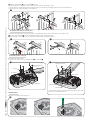
Assembling the transmission rail.
Secure the bracket to the transmission rail using the
screw and nut supplied .

Page
7
7 - Manual code:
119EV88EN
119EV88 EN ver.
5
5 09/2013 © CAME cancelli automatici S.p.A. - The data and information provided in this manual are subject to change at any time without prior notice by CAME Cancelli Automatici S.p.A.
Install the support brackets and the U-bracket on the rail.
Adapt the pierced plates, bending them, in order to compensate for the distance of the rail from the ceiling.
Secure the plates to the support brackets and the U-bracket using the screws and nuts supplied. Drill the ceiling at the point of the plate fi xing holes.
Secure the plates to the ceiling using suitable screws and anchors.
Secure the door mounting bracket to the upper door crosspiece, perpendicularly to the rail. Use the screws supplied or other suitable screws.
Secure the transmission arm to the door mounting bracket using the insert and split pin supplied.
If assembling the curved lever , secure it to the transmission arm using the screws and nuts supplied.
Securing the transmission arm to the door
Securing the operator to the rail
Fit the adapter onto the motor shaft.
The operator can be fi xed to the rail: in a standard position or orthogonally .
If mounting the operator in an orthogonal position, move the micro before instal-
lation (see the section: Moving the micro).
Rail
Shaft with adapter
Self-tapping screw
6x15
U-bracket
Microswitch
Self-tapping screw 6x15
U-bracket
Rail
Shaft with adapter
Microswitch
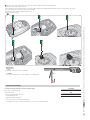
Moving the micro
Disconnect the microswitch cables and remove it.

Page
8
8 - Manual code:
119EV88EN
119EV88 EN ver.
5
5 09/2013 © CAME cancelli automatici S.p.A. - The data and information provided in this manual are subject to change at any time without prior notice by CAME Cancelli Automatici S.p.A.
Remove the cover of the operator and the cable clamp. Slide out the electrical cable and route into the through-hole.
Refi t the cable clamp so that the hole is blocked.
Use the screwdriver to pierce the preformed hole to pass the microswitch electrical cables through and fi t the cables into the micro. Secure the micro to the operator.
Connect the connectors in the respective positions on the microswitch.
Reconnect the cables as in their original confi guration (N.O). - C).
Secure the cover to the operator.
Operator latch
Latch
To release the operator, pull the cord downwards.
Locking
To lock the operator back into place, use the transmitter or a command button.
ELECTRICAL CONNECTIONS
Before intervening on the device, disconnect the line voltage.
Power supply (V - 50/60 Hz) 230 AC
Control board features:
• Motion control and obstacle detection
• Reopening during closing
• Adjustable automatic closing time
• Open-stop-close-stop from transmitter and/or button
• Courtesy light (stays on for a set time of 3 minutes and 30 seconds after an opening command.
FUSE TABLE
Line fuses (A) 5
LED
Courtesy Lights (W) ≤ 1

AF
4
2
8
91011
3
1
13
14
16
7
15
6
5
12
Page
9
9 - Manual code:
119EV88EN
119EV88 EN ver.
5
5 09/2013 © CAME cancelli automatici S.p.A. - The data and information provided in this manual are subject to change at any time without prior notice by CAME Cancelli Automatici S.p.A.
Description of the components
1. Line fuse
2. Gearmotor
3. Transformer
4. Cable inlet
5. AF board connector
6. Cable-antenna
7. Photocell connection terminal block
8. STOP button connection terminal block
9. Limit switch connection terminal block
10. Encoder connection terminal block
11. Display connection terminal block
12. Motor connections
13. Transformer connection
14. Courtesy light connection terminal block
15. Antenna connection terminal block
16. Flashing light connection terminal block
While CLOSING: it reverses the direction of movement until complete opening.
After three consecutive reversals, the door remains open, disabling automatic closing: in
order to close it, use the transmitter or a button.
While OPENING: the door stops. To resume movement, press a button or use the transmitter.
Motion control and obstacle detection

RX
TX
Page
10
10 - Manual code:
119EV88EN
119EV88 EN ver.
5
5 09/2013 © CAME cancelli automatici S.p.A. - The data and information provided in this manual are subject to change at any time without prior notice by CAME Cancelli Automatici S.p.A.
Power supply
The operator is supplied with an electric cable (L = 1.2 m) with Shuko socket already connected.
Warning devices
Flashing light (contact capacity: 24 V - 25 W max).
It fl ashes during opening and closing.
Control devices
Stop button (N.C. contact) Stops the door with the exclusion of automatic closing. To
resume movement, press the control button or other control device.
If a device is connected,
remove the jumper
OPEN-STOP-CLOSE-STOP function from the control device (N.O. contact)
Reopening contact (N.C.) while closing.
Input for safety devices such as photocells, sensitive edges and other devices compliant with the EN 12978 standard.
While the operator is closing, the opening of the contact causes the reversal of the direction of movement until completely open.
If a device is connected, remove the jumper
If a device is connected, remove
the jumper
Preparing for programming
Manually attach the door to the guide.
Power the operator. A sound means that the board is ready for programming.
Remove the transparent cover to gain access to the keys for programming.
Description of the keys
Storage is always the last phase of programming (function 5), otherwise the settings are not saved.
In the event of setting errors, disconnect and reconnect the power supply and reprogram.
Adjustment and menu advance button
Adjustment and menu
advance button
Memorisation key
transmitters
Key to access to the menu and
save changes
Display for programming and monitoring of operator functioning
L = normal operation
F = obstacle detection
H = encoder error
A = photocell activated
Safety devices
Key to symbols
PROGRAMMING

Page
11
11 - Manual code:
119EV88EN
119EV88 EN ver.
5
5 09/2013 © CAME cancelli automatici S.p.A. - The data and information provided in this manual are subject to change at any time without prior notice by CAME Cancelli Automatici S.p.A.
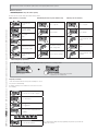
Mandatory functions
Determining the end-run points when opening
Follow the end-run point setting order indicated in this manual.
Some functions must be set so that the operator is able to work properly while others are optional
While operator is not moving
Press P for about 5
seconds.
The operator emits a single
sound and 1 appears.
Press P again,
1 fl ash.
Press +
Allow the door to reach the
desired
opening position.
Press P to save the
operation.
Determining the end run points while closing
Press +, 2 appears.
Press P, 2 fl ashes.
Press -.
Allow the door to reach the
desired closing position.
Press P to save the operation.
Checking run self-learning
Press +, 3 appears.
Press P, 3 fl ashes.
The door reaches the closing
end-run.
Press P.
The door reaches the closing
limit switch.
Memorising the programming
IT IS MANDATORY to complete programming with this function to prevent loss of settings saved!
Press + to select 5.
Press P. The display segments turn in clockwise.
Programming is successfully stored.
Adjusting sensitivity.
The door must be balanced correctly. If the sensitivity is too low, it
may cause door malfunctioning.
By default, sensitivity is set to medium level. To increase or decrease
the sensitivity:
Press P for about 5 seconds, 1 appears.
Press + and select 4.
Press P, appears.
Press + or - to select an appropriate level
of sensitivity.
Minimum Maximum Sensitivity Level
Press P to save the operation.
Memorisation is always the last programming step (function 5), otherwise the
settings are not saved.

Page
12
12 - Manual code:
119EV88EN
119EV88 EN ver.
5
5 09/2013 © CAME cancelli automatici S.p.A. - The data and information provided in this manual are subject to change at any time without prior notice by CAME Cancelli Automatici S.p.A.
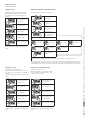
Setting the alarm
By default, the function is deactivated; when the
alarm is active the operator will emit a beep if the
door remains open for more than 10 minutes. To
activate it:
Press P for about 5 sec-
onds, 1 appears.
Press + and select 6
Press P, 0 appears.
Press + and select 1. The
alarm is now active.
Press P to save the setting.
The last phase of programming is always
storage (function 5), otherwise the settings are not
saved.
Adjusting the automatic closing intervention time;
By default, the function is disabled. To activate it:
Press P for about 5 sec-
onds, 1 appears.
Press +
and select 7.
Press P, 0 appears.
Press + and select 1.
Automatic closing is
activated and the standby
time is 30 seconds.
To change standby time before closing, press + or -.
60 seconds 90 seconds 120 seconds 150 seconds
180 seconds 210 seconds 240 seconds
Press P to save the
operation.
The last phase of programming is always storage (function 5), otherwise the settings are not saved.
The operator emits a sound for 20 seconds before the door starts to close automatically. At the same time, the
courtesy light fl ashes. When the door starts to close, the operator emits a sound and the courtesy light remains on
steadily. With the door closed, the operator does not emit any sound and the courtesy light stays on for 3 minutes.
Optional functions
Manoeuvre counter
By default, the function is disabled.
When this function is activated, after 2,000 cycles,
the operator beeps in indication of maintenance
required.
To turn off the sound, disconnect and reconnec line
voltage.
To activate:
Press P for about 5 sec-
onds, 1 appears.
Press + and select 8.
Press P, 0 appears.
Press +, 1 appears: the
function is active.
Press P to save the
operation.
The last phase of programming is always
storage (function 5), otherwise the settings are not
saved.
Automatic Closing Warning Function
By default, the function is active.
With function enabled, the operator emits a sound
for 20 seconds before starting automatic closing.
To disable, proceed as follows:
Press P for about 5 sec-
onds, 1 appears.
Press + and select 9
Press P, 1 appears.
Press -, 0 appears: the
function is disabled.
Press P to save the setting.
The last phase of programming is always
storage (function 5), otherwise the settings are not
saved.

AF
AF
Page
13
13 - Manual code:
119EV88EN
119EV88 EN ver.
5
5 09/2013 © CAME cancelli automatici S.p.A. - The data and information provided in this manual are subject to change at any time without prior notice by CAME Cancelli Automatici S.p.A.
Activating the radio control
Additional outdoor antenna
Radio frequency card
For proper operation, before inserting the AF plug-in card,
INTERRUPT LINE VOLTAGE.
Disconnect the indoor antenna and connect
the outdoor antenna to the appropriate
terminals on the board.
Saving the transmitters
You can store up to a maximum of 16* di erent codes/users With the operator at a
standstill:
Press and hold down S until
0 appears on the left side of the display. The 0 segments
on the right side of the display rotate clockwise.
Press the key to save twice in a row to memorise it.
* When attempting to memorise the 17th code (transmitter), the courtesy light
fl ashes slowly 5 times to show that the memory is full.
Deleting the transmitters
Press and hold down S until
0 appears on the left side of the display. The 0 segments
on the right side of the display rotate clockwise.
When the 0 on the left disappears, release the S key: the
transmitters have been deleted.

RX
TX
Page
14
14 - Manual code:
119EV88EN
119EV88 EN ver.
5
5 09/2013 © CAME cancelli automatici S.p.A. - The data and information provided in this manual are subject to change at any time without prior notice by CAME Cancelli Automatici S.p.A.
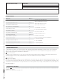
Periodic maintenance
Periodic maintenance log to be completed by the user (every six months)
Extraordinary maintenance log
Extraordinary maintenance
The table below is used to note any extraordinary maintenance, repairs or improvements carried out by
specialist companies.
Extraordinary maintenance must be carried out by specialist technicians.
Installation technician stamp Operator name
Date of intervention
Technician signature
Customer signature
Intervention carried out __________________________________________________________________________________
__________________________________________________________________________________________________
__________________________________________________________________________________________________
__
MAINTENANCE
Before any maintenance, disconnect line voltage to prevent any possible dangerous situations that can be caused by accidental movement of the operator.
Lubricate the rotation points with grease whenever abnormal vibrations or squeaking occurs.
Date Notes Signature

Page
15
15 - Manual code:
119EV88EN
119EV88 EN ver.
5
5 09/2013 © CAME cancelli automatici S.p.A. - The data and information provided in this manual are subject to change at any time without prior notice by CAME Cancelli Automatici S.p.A.
Malfunctions What to do
The operator does not open or close 1-3-25
1 - Check the power supply and line fuses
3 - The NO command contact (7-2) is open
4 - The NC safety contact (2-C1) is open
5 - The NC safety contacts are open
9 - Check that a time is set on menu 7
10 - Check the correct direction of travel
14 - Re-memorise the radio code
16 - Adjust the sensitivity on menu 4
17 - Eliminate mechanical friction
18 - Enter (or copy) the same code for all the transmitters
19 -
Check photocell operation
23 - Check door balancing
24 - Check belt/chain tension
25 - Encoder malfunctioning: disconnect and reconnect power to the board
The operator opens but does not close 4-10-23
The operator closes but does not open 23
The operator does not close automatically 9-10
The transmitter does not work 14
The operator is too powerful 16
The operator is not powerful enough 16-17-23-24
The operator reverses direction
16-17-23-24
Only one transmitter is operational 18
The photocells do not respond 4-19
The voltage present indicator LED is off 1-3
The operator reverses direction at the end run 10-17-23
The operator starts slowly 17-23-24
TROUBLESHOOTING
DISMANTLING AND DISPOSAL
CAME CANCELLI AUTOMATICI S.p.A. implements an EN ISO 14001-certified and compliant Environmental Management System at its plants, to ensure environmental
protection.
Please continue our efforts to protect the environment, something that CAME considers to be one of the foundations in developing its business and market
strategies, simply by observing brief recommendations as regards disposal:
DISPOSAL OF PACKAGING
Packaging components (cardboard, plastic, etc.) can be disposed of together with normal household waste without any difficulty, by simply separating the different types of
waste and recycling them.
Before proceeding, it is always advisable to check specific regulations in force in the place of installation.
DISPOSE OF PROPERLY!
DISPOSAL OF THE PRODUCT
Our products are made with different materials. Most of them (aluminium, plastic, iron, electrical cables) can be disposed of together with normal household waste. They can
be recycled if collected, sorted and sent to authorised centres. Other components (control boards, transmitter batteries, etc.), on the other hand, may contain pollutants. They
should therefore be removed and handed over to companies authorised to recover and recycle them.
Before proceeding, it is always advisable to check specific regulations in
force in the place of disposal.
DISPOSE OF PROPERLY!
DECLARATION OF CONFORMITY
Declaration - Came Cancelli Automatici S.p.A. declares that this device complies with the essential requirements and other relevant provisions established in Directives
2006/95/EC and 1999/5/EC.
Reference code for requesting a true copy: DDC L V001
Installation technician stamp Operator name
Date of intervention
Technician signature
Customer signature
Intervention carried out __________________________________________________________________________________
__________________________________________________________________________________________________
__________________________________________________________________________________________________
__

IT • Per ogni ulteriore informazione su azienda, prodotti e assistenza nella vostra lingua:
EN • For any further information on company, products and assistance in your language:
FR • Pour toute autre information sur la société, les produits et l’assistance dans votre langue :
DE • Weitere Infos über Unternehmen, Produkte und Kundendienst bei:
ES • Por cualquier información sobre la empresa, los productos y asistencia en su idioma:
NL • Voor meer informatie over het bedrijf, de producten en hulp in uw eigen taal:
PT • Para toda e qualquer informação acerca da empresa, de produtos e assistência técnica, em sua língua:
PL •
Wszystkie inne informacje dotyczące fi rmy, produktów oraz usług i pomocy technicznej w Waszym języku znajdują się na stronie:
RU •
Для получения дополнительной информации о компании, продукции и сервисной поддержке на вашем языке:
HU • A vállalatra, termékeire és a műszaki szervizre vonatkozó minden további információért az Ön nyelvén:
HR • Za sve dodatne informacije o poduzeću, proizvodima i tehničkoj podršci:
UK • Для отримання будь-якої іншої інформації про компанію, продукцію та технічну підтримку:
CAME Cancelli Automatici S.p.a.
CAME Cancelli Automatici S.p.a.
Via Martiri Della Libertà, 15
31030
Dosson Di Casier
Dosson Di Casier (Tv)
(+39) 0422 4940
(+39) 0422 4941
Assistenza Tecnica/Numero Verde 800 295830
Assistenza Tecnica/Numero Verde 800 295830
www. came.com
www. came.com
English
English - Manual code:
119EV88EN
119EV88 EN ver.
5
5 09/2013 © CAME cancelli automatici S.p.A.
The data and information provided in this manual are subject to change at any time without prior notice by CAME Cancelli Automatici S.p.A.
-
 1
1
-
 2
2
-
 3
3
-
 4
4
-
 5
5
-
 6
6
-
 7
7
-
 8
8
-
 9
9
-
 10
10
-
 11
11
-
 12
12
-
 13
13
-
 14
14
-
 15
15
-
 16
16


CAME v6000 Installation guide
- Category
- Garage Door Opener
- Type
- Installation guide
Ask a question and I''ll find the answer in the document
Finding information in a document is now easier with AI
Related papers
-
CAME BX-246 Installation guide
-
CAME FROG-A Installation guide
-
CAME KRONO KR310 Installation guide
-
-
-
-
-
-
-
Other documents
-
Nice Spin11KCE Owner's manual
-
 CubiCubi Computer Desk 40" Study Writing Table for Home Office, Modern Simple Style PC Desk, Black Metal Frame, Black User manual
-
3com 900-0387-01 User manual
-
Merlin G715D Instructions For Installation And Use Manual
-
ZTE V6000 Style Q User manual
-
Merlin G950 Instructions For Installation & Use
-
Somfy Axorn User manual
-
TEAC WAP-V6000 Owner's manual
-
 Mhouse GDS Owner's manual
-
V-ZUG 64009 Installation guide

