Page is loading ...


Table of Contents
i
Contents
Task-Oriented Reference...............................1
Measurement Flow.........................................3
Introduction..................................................... 4
Verifying Package Contents...........................4
Safety Information ..........................................6
Operating Precautions....................................8
Chapter 1 Overview 11
1.1 Product Overview and Features ........ 11
Block Diagram ..........................................14
1.2 Names and Functions of the Parts ..... 15
1.3 Screen Organization ..........................17
Chapter 2 Measurement
Preparations 21
2.1 Connecting the Power Cord............... 22
2.2 Connecting Measurement Probes and
Test Fixtures ...................................... 23
Making Your Own Measurement Probes ..24
2.3 Turning the Power On and Off ........... 25
Chapter 3 Measurement Set-
tings (Basic Measurements) 27
3.1 Pre-Operation Inspection ...................27
3.2 Measuring Object Types ....................28
3.3 Setting the Measurement Speed .......29
3.4 Setting Measurement Start Conditions
(Trigger Source) .................................31
3.5 Selecting the Measurement Range .... 32
3.6 Zero Adjustment ................................. 34
3.7 Judging Measurement Values
(Comparator Function) .......................36
Enabling and Disabling the
Comparator Function ................................37
Decide According to Reference Value and
Tolerance (REF% Mode) ..........................37
Decide According to Upper/Lower Thresholds
(ABS Mode) ............................................. 39
3.8 Confirming Faulty Measurements ......40
Chapter 4 Customizing Mea-
surement Settings 43
4.1 Making Range-Specific Measurement
Settings ..............................................43
4.2 Setting Pre-Measurement Delay ........44
4.3 Compensating Measured Values
(Scaling Function) .............................46
4.4 Setting the Measurement Integration
Time Option ........................................48
4.5 Checking for Poor or Improper Contact
(Contact Check Function) ...................50
4.6 Improving Probe Contact
(Contact Improver Function) ...............52
4.7 Detecting Measurement Voltage Faults
(Voltage Level Monitor Function) .......55
4.8 Applying Current Only When Measuring
(Current Mode Setting) .......................56
4.9 Test for Short-Circuited Probe
(Probe Short-Circuit Detection Function)
............................................................57
4.10 Comparing the Measurement Settings of
Two Instruments
(Settings Monitor Function) ................59
4.11 Retrying Measurement After a Fault
(Retry Function) .................................62
4.12 Limiting Measurement Voltage
(Applied Voltage Limiter Function) .....64
4.13 Maintaining Measurement Precision
(Self-Calibration Function) ..................65
4.14 Compensating for Thermal EMF Offset
(Offset Voltage Compensation - OVC) 65
Chapter 5 System Settings 67
5.1 Disabling and Enabling Key Operations
............................................................67
Disabling Key Operations
(Key-Lock Function) ................................. 67
1
2
3
4
RM3542D962-01
5

Table of Contents
ii
Re-Enabling Key Operations
(Key-Lock Cancel) ................................... 68
5.2 Setting the Comparator Judgment and
Key Beepers ......................................69
Enabling or Disabling the Key Beeper ..... 69
Setting the Comparator Judgment Beeper 70
5.3 Power Line Frequency Manual Setting
............................................................71
5.4 Setting the Clock ................................72
5.5 Adjusting Screen Contrast ..................73
5.6 Adjusting the Backlight .......................74
5.7 Initializing (Reset) ...............................75
Default Settings ........................................ 76
Chapter 6 Storing and
Exporting Data 79
6.1 Storing Data at Specified Timing
(Data Memory Function) .....................80
6.2 Store as soon as Measurement is Stable
(Auto-Memory Function) .....................81
6.3 Performing Statistical Calculations on
Measurement Values .........................84
Using Statistical Calculations ................... 85
Confirming, Printing, and Erasing Statistical
Calculation Results .................................. 86
6.4 Auto-Exporting Measurement Values
(at End of Measurement)
(Data Output Function) .......................87
Chapter 7 Printing 89
7.1 Connecting the Printer ........................89
Connecting the Printer to the Instrument . 90
7.2 Setting the Instrument ........................91
7.3 Printing ...............................................93
Printing Measurement Values and
Comparator Judgments ........................... 93
Printing Statistical Calculation Results .... 93
Chapter 8 External Control 95
8.1 Ext. I/O Connectors and Signals ........95
Connector Type and Signal Pinouts ........ 96
Signal Descriptions .................................. 97
8.2 Timing Chart .......................................99
8.3 Internal Circuitry ............................... 102
Electrical Specifications ......................... 103
Connection Examples ............................ 104
8.4 Ext. I/O Settings ............................... 105
Setting the End-of-Measurement Signal
Output (EOM
Signal Setting) .................. 105
Setting the Trigger Signal (TRIG) Logic . 106
8.5 Q&A Regarding External Control ..... 107
8.6 Supplied Connector Assembly ......... 108
Chapter 9 Communications
(RS-232C/ GP-IB Interface) 109
9.1 Overview and Features of Interfaces 109
9.2 Specifications ................................... 110
9.3 Connecting ....................................... 111
Using the RS-232C Interface ................. 111
Using the GP-IB Interface
(RM3542-51 only) ................................. 112
9.4 Configuring the Communications Protocol
.......................................................... 113
Configuring RS-232C Interface
Communications Protocol ...................... 113
Configuring the GP-IB Interface
Communication Protocol (RM3542-51 only)
............................................................... 114
Set the Measurement Value Transmission
format (common for RS-232C and GP-IB)
................................................................ 115
9.5 Communication Methods ................. 116
To Cancel the Remote Status
(Enter the Local Status) ......................... 116
Message Format .................................... 117
Output Queue and Input Buffer .............. 120
Status Byte Register .............................. 121
Event Registers ...................................... 123
Initialization Items ................................... 126
Command Execution Time ..................... 127
Errors During Communications .............. 127
9.6 Message List .................................... 128
Shared Commands ................................ 128
Device-Specific Commands ................... 130
9.7 Message Reference ......................... 134
Message Reference Interpretation ......... 134
Shared Commands ................................ 135
Device-Specific Commands ................... 139
9.8 Data exporting methods ................... 163
9.9 Sample Programs ............................ 165
Using Visual Basic 5.0 or 6.0 ................. 165

Table of Contents
iii
Create with Visual Basic 2005 ................175
Sample Programs (Visual Basic 2005) ...177
9.10 Device Compliance Documents....... 179
Chapter 10 Specifications 181
Chapter 11 Maintenance
and Service 195
11.1 Troubleshooting ............................... 195
Inspection and Repair .............................195
11.2 Cleaning ...........................................196
11.3 Error Displays and Solutions ............ 197
11.4 Disposing of the Instrument ............. 199
Removing the Lithium Battery .................199
Appendix A 1
Appendix 1 Four-Terminal (Voltage-Drop)
Method......................................A 1
Appendix 2 Effect of Thermal emf ...............A 2
Appendix 3 Unstable Measurement Values.A 3
Appendix 4 Rack Mounting..........................A 8
Appendix 5 Dimensional diagram ..............A 10
Appendix 6 Calibration...............................A 11
Appendix 7 Adjustment..............................A 13
Appendix 8 Table of Comparison Commands
ADEX AX-162D / for this instrument
................................................A 14
Appendix 9 Zero Adjustment .....................A 16
Index Index 1
6
7
8
9
10
11
12
5
Index
Appendix

Table of Contents
iv

Task-Oriented Reference
1
Task-Oriented Reference
To minimize measurement error
Setting the Measurement Speed (p. 29)
Setting the measurement speed integration time option (p. 48)
Zero Adjustment (p. 34)
To judge measurement results
Judging Measurement Values (Comparator Function) (p. 36)
Comparing the Measurement Settings of Two Instruments (Settings
Monitor Function) (p. 59)
To correct faulty measurements
Confirming Faulty Measurements (p. 40)
Improving Probe Contact (Contact Improver Function) (p. 52)
To enhance the reliability of
inspection
Checking for Poor or Improper Contact (Contact Check Function) (p.
50)
Detecting Measurement Voltage Faults (Voltage Level Monitor Func-
tion) (p. 55)
Test for Short-Circuited Probe (Probe Short-Circuit Detection Function)
(p. 57)
Comparing the Measurement Settings of Two Instruments (Settings
Monitor Function) (p. 59)
To inspect the 03015 mm or 0201
mm (Imperial 008004) size com-
ponents
Limiting Measurement Voltage (Applied Voltage Limiter Function)
(p. 64)
To automatically store measure-
ment values
Store as soon as Measurement is Stable (Auto-Memory Function)
(p. 81)
To print measurement results
Printing (p. 89)
To measure by connecting with
PLC (Control equipment)
(PLC: Programmable Logic Controller)
External Control (p. 95)
Communications (RS-232C/ GP-IB Interface) (p. 109)
To connect to a computer
Communications (RS-232C/ GP-IB Interface) (p. 109)

Task-Oriented Reference
2
To enable auto-exporting
measurement values to the
computer
(Available only with RS-232C interface)
Auto-Exporting Measurement Values (at End of Measurement) (Data
Output Function) (p. 87)
To check operation
Setting Measurement Start Conditions (Trigger Source) (p. 31)
Internal trigger [INT]
Calibration (p. A11)

Measurement Flow
3
Be sure to read the "Operating Precautions" (p. 8) before use.
Measurement Flow
Installing, Connecting and Turning On
Communicating with
the computer (p. 109)
Printing (p. 89)
External control
(p. 95)
EXT.I/O
RS-232C
GP- IB
Comparing Two Instruments (p. 59)
SET MONITOR
Connecting the Power Cord (p. 22)
Turning Power On (p. 25)
Connecting (p. 21)
Installing (p. 8)
Connecting Measurement Probes (p. 23)
Settings of RM3542A
Setting measuring conditions
(as needed)
Confirm the screen configuration
(p. 17)
Confirm the initial setup (p. 76)
• Basic Settings(p. 27)
• Configure settings for your
specific conditions (p. 43)
•
System-related settings (p. 67)
When changing settings
Change basic settings
such as measurement
speed
Change detailed settings
(measurement condi-
tions and system-related
settings)
Setting judgment criteria
(p. 36)
Calculation, Printing, Communication, and External Control Settings
Transmitting data (p. 87) Printing (p. 89)
Computer communications
(p. 109)
External Control (p. 95)
Enable statistical
calculation (p. 84)
Instrument interface settings must
be configured before printing, using
communications or external control.
When Finished
Turning Power Off (p. 25)

Introduction
4
Thank you for purchasing the Hioki Model RM3542A (RM3542-50/RM3542-51) Resistance
Meter.
To obtain maximum performance from the instrument, please read this manual first, and keep
it handy for future reference.
Model RM3542-51 includes the GP-IB interface.
Registered trademarks
• Windows and Visual Basic are either registered trademarks of Microsoft Corporation in the
United States and other countries.
• Teflon is a registered trademark of E. I. du Pont de Nemours and Company.
Inspection
Content confirmation
Introduction
Verifying Package Contents
When you receive the instrument, inspect it carefully to ensure that no damage occurred during ship-
ping. In particular, check the accessories, panel switches, and connectors. If damage is evident, or if it
fails to operate according to the specifications, contact your authorized Hioki distributor or reseller.
Confirm that these contents are provided.
This instrument 1
Accessories
Instruction Manual (This document) ........... 1
Operation Guide ......................................... 1
Power Cord (p. 22)
EXT.I/O Male Connector (p. 108)

Verifying Package Contents
5
Options
Contact your authorized Hioki distributor or reseller for details.
Precautions during shipping
During shipment of the instrument, handle it carefully so that it is not damaged due to a vibra-
tion or shock.
Measurement Probes and Fixtures
(connect to measurement jacks)
Model 9140-10 4-terminal Probe
Model 9262 Test Fixture
Model 9263 SMD Test Fixture
Model IM9100 SMD Test Fixture
Alligator-clip-type measurement probes.
These general-purpose dual-electrode clips fit
a wide range of conductor thicknesses.
Measurable terminal diameter:
0.3 mm to 5 mm
This fixture is for measuring
lead components.
Measurable sample dimension:
Lead diameter:
φ0.3 mm to φ2 mm
Lead pitch: 5 mm or more
(less than 20 mΩ residual resistance after
zero adjustment)
This fixture is for measuring
chip components.
Measurable sample dimension:
Sample width: 1 mm to 10 mm
(less than 20 mΩ residual resistance after
zero adjustment)
This fixture is for measuring ultra-small
SMD components.
Measurable sample dimension:
JIS(EIA): Approx. L mm x W mm
0402 (01005): 0.4 mm x 0.2 mm
0603 (0201): 0.6 mm x 0.3 mm
1005 (0402): 1.0 mm x 0.5 mm
(less than 100 mΩ residual resistance after zero
adjustment)
Interface Cables
Model 9637 RS-232C Cable
(9-pin to 9-pin/crossover cable/1.8
m)
Model 9638 RS-232C Cable
(9-pin to 25-pin/crossover cable/1.8
m)
Model 9151-02 GP-IB Connector
Cable (2 m)

Safety Information
6
This instrument is designed to conform to IEC 61010 Safety Standards, and has been thor-
oughly tested for safety prior to shipment. However, using the instrument in a way not
described in this manual may negate the provided safety features.
Before using the instrument, be certain to carefully read the following safety notes:
In this document, the risk seriousness and the hazard levels are classified as follows.
Safety Information
If persons unfamiliar with electricity measuring instrument are to use the instrument, another
person familiar with such instruments must supervise operations.
Mishandling during use could damage to the instrument. Be certain that you understand the
instructions and precautions in the manual before use.
Marks on This Instrument
Indicates cautions and hazards. When the symbol is printed on the instrument, refer to a correspond-
ing topic in the Instruction Manual.
Indicates AC (Alternating Current).
Alarm Symbols
Indicates an imminently hazardous situation that will result in death or serious injury to the operator.
Indicates a potentially hazardous situation that may result in death or serious injury to the operator.
Indicates a potentially hazardous situation that may result in minor or moderate injury to the operator
or damage to the instrument or malfunction.
Indicates advisory items related to performance or correct operation of the instrument.
Symbols for Various Standards
This symbol indicates that the product conforms to regulations set out by the EC Directive.
This symbol indicates laws and regulations regarding the disposal of electrical and electronic appli-
ances in the Member States of EU (WEEE directive).

Safety Information
7
Accuracy
We define measurement tolerances in terms of f.s. (full scale), rdg. (reading) and dgt. (digit) values, with the
following meanings:
Measurement categories
To ensure safe operation of measuring instruments, IEC 61010 establishes safety standards for various elec-
trical environments, categorized as CAT II to CAT IV, and called measurement categories.
Other Symbols
Indicates the prohibited action.
(p. )
Indicates the location of reference information.
*
Indicates that descriptive information is provided below.
[ ]
Square brackets indicate instrument display labels (such as setting item names).
SET
(Bold characters)
Bold characters within the text indicate operating key labels.
Unless otherwise specified, Windows represents Windows 95, 98, Me, Windows NT4.0, Windows 2000, Windows XP, or
Windows Vista.
Click: Press and quickly release the left button of the mouse.
Double click: Quickly click the left button of the mouse twice.
f.s. (maximum display value)
The maximum displayable value. This is usually the name of the currently selected range.
rdg. (reading or displayed value)
The value currently being measured and indicated on the measuring instrument.
dgt. (resolution)
The smallest displayable unit on a digital measuring instrument, i.e. a "1" as the least-significant digit.
• Using a measuring instrument in an environment designated with a higher-num-
bered category than that for which the instrument is rated could result in a severe
accident, and must be carefully avoided.
• Never use a measuring instrument that lacks category labeling in a CAT II to CAT IV
measurement environment. Doing so could result in a serious accident.
CAT II:
When directly measuring the electrical outlet receptacles of the primary electrical circuits
in equipment connected to an AC electrical outlet by a power cord (portable tools, house-
hold appliances, etc.)
CAT III:
When measuring the primary electrical circuits of heavy equipment (fixed installations) con-
nected directly to the distribution panel, and feeders from the distribution panel to outlets
CAT IV:
When measuring the circuit from the service drop to the service entrance, and to the
power meter and primary overcurrent protection device (distribution panel)

Operating Precautions
8
Follow these precautions to ensure safe operation and to obtain the full benefits of the various
functions.
Before using the instrument for the first time, verify that it operates normally to ensure that no
damage occurred during storage or shipping. If you find any damage, contact your authorized
Hioki distributor or reseller.
Installing
• To prevent overheating, be sure to leave the specified clearances around the instrument.
• Install the instrument with the bottom facing down.
Operating Precautions
Preliminary Checks
Instrument Installation
Installing the instrument in inappropriate locations may cause a malfunction of instru-
ment or may give rise to an accident. Avoid the following locations:
• Exposed to direct sunlight or high temperature
• Exposed to corrosive or combustible gases
• Exposed to a strong electromagnetic field or electrostatic charge
• Near induction heating systems (such as high-frequency induction heating systems
and IH cooking equipment)
• Susceptible to vibration
• Exposed to water, oil, chemicals, or solvents
• Exposed to high humidity or condensation
• Exposed to high quantities of dust particles
Do not place the instrument on an unstable table or an inclined place. Dropping or knocking
down the instrument can cause injury or damage to the instrument.
The instrument can be used with the stand (p. 16) in the upright position.
It can also be rack-mounted (p. A8).
50 mm or more
10 mm or more
Rear Panel
50 mm or more
Unplugging the power cord kills power to the instrument. Be sure to provide enough
unobstructed space to unplug the power cord immediately in an emergency.

Operating Precautions
9
This instrument may cause interference if used in residential areas. Such use must be
avoided unless the user takes special measures to reduce electromagnetic emissions to pre-
vent interference to the reception of radio and television broadcasts.
Handling the Instrument
To avoid damage to the instrument, protect it from physical shock when transporting and
handling. Be especially careful to avoid physical shock from dropping.
Handling the Fixture
Before using a test fixture, read the instructions provided with it.
Before Turning Power On
• Before turning the instrument on, make sure the supply voltage matches the voltage
indicated on its power connector. Connection to an improper supply voltage may
damage the instrument and present an electrical hazard.
• To avoid electrical accidents and to maintain the safety specifications of this instru-
ment, connect the power cord provided only to an outlet.
Avoid using an uninterruptible power supply (UPS) or DC/AC inverter with rectangular wave
or pseudo-sine-wave output to power the instrument. Doing so may damage the instrument.
Before Connecting EXT. I/O Connector
To avoid electric shock or damage to the equipment, always observe the following
precautions when connecting to the EXT. I/O connectors:
• Always turn off the power to the instrument and to any devices to be connected
before making connections.
• During operation, a wire becoming dislocated and contacting another conductive
object can be serious hazard. Use screws to secure the EXT. I/O connectors.
To avoid damage to the instrument, always observe the following precautions when
connecting to the EXT. I/O connector.
• Do not apply voltage or current to the EXT. I/O terminals that exceeds their ratings
(p. 103).
• Ensure that devices and systems to be connected to the EXT. I/O terminals are
properly isolated.
• When driving relays, be sure to install diodes to absorb counter-electromotive
force.
• The IISO_5 V pin of the EXT. I/O connector is a 5 V power output. Do not apply exter-
nal power to this pin. Be careful not to short-circuit ISO_5 V to ISO_COM.
• The IISO_12 V pin of the EXT. I/O connector is a 12 V power output. Do not apply
external power to this pin. Be careful not to short-circuit ISO_12 V to ISO_COM.
See "Connector Type and Signal Pinouts" (p. 96).

Operating Precautions
10
Before Connecting to the RS-232C Connector or SET MONITOR Connector
• Use a common ground for both the instrument and connected device.
Using different ground circuits will result in a potential difference between the instrument's
ground and the connected device.
If the communications cable is connected while such a potential difference exists, it may
result in equipment malfunction or failure.
• Before connecting or disconnecting any the communications cable, always turn off the
instrument and the connected device. Failure to do so could result in equipment malfunc-
tion or damage.
• After connecting the communications cable, tighten the screws on the connector securely.
Failure to secure the connector could result in equipment malfunction or damage.
Before Measuring
To avoid electrical hazards and damage to the instrument, do not apply voltage
exceeding the rated maximum to the EXT. I/O connectors.
• Do not apply any voltage to the measurement jacks. Doing so may damage the unit.
• Never attempt to measure at a point where voltage is present. In particular, do not mea-
sure a transformer or motor immediately after a temperature increase test or withstand-
voltage test, as the instrument could be damaged by induced voltage or residual charge.
• Battery internal resistance cannot be measured with this instrument. It will sustain damage.
To measure the battery internal resistance, we recommend the Hioki 3554, 3555, BT3562,
BT3563 and 3561 Battery HiTesters.
• To obtain the guaranteed measurement accuracy, allow at least 30 minutes warm-up.
• The instrument internally retains all settings (but not measurement values), such as mea-
surement range and comparator settings. However, measurement settings made through
the RS-232C or GP-IB interface are not memorized.
• In the 100
Ω or higher ranges (LOW POWER: OFF setting), a measurement error may
occur due to the influence of thermo electromotive force.
• The DC resistance of a power transformer cannot be measured. When measuring objects
with a large L, such as choke coils and other inductors, measurement values may be
unstable. In such cases, contact your authorized Hioki distributor or reseller.
• Carefully insulate all H
CUR
, H
POT
, L
POT
and L
CUR
wiring. Proper 4-terminal measurements
cannot be performed and an error will occur if the core and shield wires touch.

1.1 Product Overview and Features
11
1
Overview Chapter 1
1.1 Product Overview and Features
This instrument employs the 4-terminal method to quickly and accurately measure the DC resistance of
components, such as resistors and ferrite beads.
It includes advanced contact-check, comparator, and data output functions. The intuitive user interface
and high noise immunity are ideal for use with taping machines and separators.
Resistance Measurement
The factory defaults (initial settings)
are optimized for chip-component re-
sistance measurements. It can also
measure devices that are otherwise
difficult to measure with a high cur-
rent, such as ferrite bead and small
multilayer inductors (low-power re-
sistance measurement) (p. 28).
It is also suitable for measuring impe-
rial 008004 sized components with
small rated voltage (Applied Voltage
Limit Function) (p. 64)
Interface Communications
Connect the instrument to a con-
troller via the RS-232C or GP-IB
interface to control this instru-
ment or acquire the measure-
ment data
(p. 109)
Send the measurement value
and calculation results to the
printer.
Use a commercially available print-
er with a serial interface to print the
measurement values and calcula-
tion results. (p. 89)
Save and Output the Mea-
surement Values
Measurement values can be stored
in the internal memory (p. 79).
Statistical calculations can be per-
formed on the stored data, which
can be transferred to a computer in
batch form (however, stored data
cannot be confirmed internally).
Judge the Measurement Values
Measurement values are compared
with a pre-specified reference value
or range, and the result is outputted
externally and indicated by the
COMP indicators (comparator func-
tion) (p. 36)
Connect a PLC or I/O Board
By connecting to the EXT. I/O con-
nector, it is possible to control the
instrument from a PLC. In addition
to the comparator results, various
measurement anomaly signals
can be outputted. (p. 95)
Upper limit
Lower limit
When using two instruments, a differ-
ence in settings disables measure-
ment and causes a warning
notification (Setting Monitor Function)
(p. 59).
Optional Hioki probes and fixtures are
available to con-
nect to the mea-
surement jacks
(BNC jacks
(p. 5)).
Alternatively,
commercially
available cables,
such as the 1.5D-
2 V coax, can be
used (p. 24)

1.1 Product Overview and Features
12
Ultra Fast and Accurate Measurements
Increase Productivity
The factory default settings are optimized for chip-com-
ponent resistance measurements. Enhanced contact-
to-measurement and contact check-to-determination,
within 1 ms.
When using the low-power resistance measurement
and the 100 mΩ to 10 Ω ranges, the offset-voltage com-
pensation (OVC) function minimizes the effects of ther-
mal emf (p. 65).
Because measurement results are judged as pass/fail
with a 10 ppm resolution, it is ideal for high-speed Class
B resistor testing.
High-Speed Data Output and Ample Memory
The Data Output function transfers measured data at
5 ms/sample, even via RS-232C.
Up to 30,000 measurements can be stored, and all
data can be exported at the end of measuring each
reel.
This function is ideal for system setup, debugging and
process management.
Multiple Interfaces
EXT. I/O is a noise proofed structure isolated from the
measurement and control circuits (p. 95).
All data can be acquired in real time using the built-in
38.4-kbps high-speed RS-232C interface.
Connect the commercially available printer with a se-
rial interface to print the measurement values and sta-
tistical calculation results (p. 89)
The GP-IB interface can also be used for Model
RM3542-51 (specified when shipping (p. 109)).
Low-Power Function (p. 28)
For ranges from 1000 mΩ to 1000 Ω, the low-power
resistance measurement is provided to minimize the
measurement current. Safely measure devices that
are otherwise difficult to measure with high current,
such as ferrite-bead and multilayer inductors.
Clearly Visible Display and Intuitive Opera-
tion
The high-contrast LCD provides clear visibility, help-
ing to avoid setting mistakes. The optimum range is
selected automatically when comparator thresholds
are entered.
The Auto Memory Function Is Convenient
for Sampling Tests(p. 81)
The auto memory function is convenient for sampling
tests after screen-printing.
When the measurement values become stable, the
measurement value is automatically acquired and sta-
tistical calculations are performed at the same time.
The beeper gives a notification when the specified
number of values are stored.
Selecting [PRINT] (screen display) prints the mea-
surement values and statistical calculation results(p.
93).
Fixtures for Component Measurements (p. 5)
The BNC-type measurement jacks exhibit good noise
immunity.
Ready availability and easy assembly ensure a
smooth system setup.
Various test fixtures are available for Hioki LCR HiT-
esters.
Features

1.1 Product Overview and Features
13
1
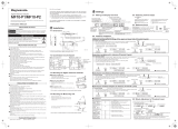
Reliable Contact Checks (p. 50)
Contact checking (that was previously performed be-
fore and after measuring) is now performed during
measurement, so probe bounce and contact resistance
fluctuations can be detected. Contact checking time
can be shortened, improving tact times.
Features
Measurement Circuit Strongly Immune to
Contact Resistance Fluctuations
The effects of contact resistance fluctuations are re-
duced even when scattering occurs near the end of
probe life. Such effects are minimized by the fast re-
sponse of the measurement circuit.
Contact Improvement Function
(Contact Improver) (p. 52)
The Contact Improver function improves bad contacts
between probes and test samples. Contacts errors are
reduced by penetrating oxidation and impurities be-
tween probes and samples.
Reducing contact errors can increase productivity and
quality. The intensity of the contact improver function
can be adjusted according to probe type.
Reject Faulty Data - Voltage Level Monitor
Function (p. 55)
When the contact resistance of the H
CUR
and L
CUR
leads fluctuates, the measurement current changes
momentarily. Such momentary changes are not detect-
able by typical contact checking.
The Voltage Level Monitor Function indicates a contact
error if the detection voltage changes significantly. It
can enhance the reliability of the measurement value.
Minimize Human Error and Risk
- Settings Monitor Function (p. 59)
If the settings are found to be different after comparing
the setting conditions of two instruments, an alarm is
sounded to prohibit the TRIG input. Helps to prevent
human errors by avoiding setting mistakes.
Reliable Four-Terminal Measurement -
Probe Short-Circuit Detection Function (p.
57)
If a conductive foreign object is present between the
POT and CUR probe tips, the reliable four-terminal
measurements cannot be maintained. When not
measuring, resistance between the POT and CUR
probe tips is measured and short-circuit probe anom-
alies are detected.
Strong Electrical Noise Immunity
The specified measurement accuracy is achieved
even with a ±1.5 kV mixed pulse noise. The floating
measurement section design is highly impervious to
electrical noise, minimizing the effect on measure-
ment values even when turning large-induction mo-
tors on and off.
The free-range power supply input (90 to 264 V) is
essentially unaffected by voltage fluctuations, so sta-
ble measurements are possible even under poor
power conditions.
DUT
Foreign Object
POT
CUR
DUT electrode
Previously
RM3542A
Contact Condition
Contact
Check
Measuring
Probe Bounce
Contact
Condition
Detection
Voltage
Error
Good Contact
Poor Contact
An error occurs
because the detection
voltage changes significantly.
Good Contact
ERROR
Measurement
Contact Check
Contact Condition
Contact Improvement
Function (Contact
Improver)
Contact Improvement
Measuring
Contact Check
ONON

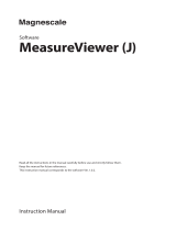
1.1 Product Overview and Features
14
• A constant current (determined by the measurement range) is applied between the H
CUR
and L
CUR
terminals while
voltage is measured between the H
POT
and L
POT
terminals. The resistance value is obtained by dividing the measured
voltage (B) by the constant current flow (A). (
A, B)
• The effects of a large offset voltage, such as from thermal emf, are reduced by reversing the current and measuring
twice in positive and negative directions (A). (A)
• The constant current source (A) and voltmeter (B) circuit designs are largely unaffected by contact resistance. (A, B)
• Faulty measurement values caused by unstable or chattering contact conditions can be eliminated by monitoring (C)
the detection voltage (B) waveform (voltage level monitor function). (B, C)
• The voltmeter is provided with sufficient time for integration (the default setting is 0.3 ms) to achieve stable measure-
ments. (The integration time can be reduced to 0.1 ms to support higher speeds.) (B)
• Before measuring, the Contact Improver circuit (D) optimizes the contact when the probes touch the DUT. (D)
• Also, performing contact checking (E) before measuring can detect short circuits between the CUR and POT terminals
caused by a clogged probe tip (probe short-circuit detection function). (
E)
• When measurement starts, the contact check circuit (E) and constant current monitor (F) are activated to monitor for
faulty conditions while measuring. (
E, F)
• The dual CPU (C and G) design provides ultra-high-speed measurements and a fast system response. (C, G)
• Protection from electrical noise is provided by the isolation between the Measurement and Control blocks (H). (H)
• The 90 V to 264 V wide range switching power supply (I) can provide stable measurements even in poor power quality
environments. (I)
Block Diagram
AB
C
D
E
F
G
H
I
E
D
/