AAI NJ300S LCR Impedance Tester User manual
- Type
- User manual
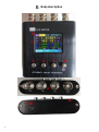
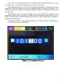
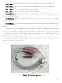
AAI NJ300S LCR Impedance Tester is a portable device designed to measure the performance parameters of basic components like resistors, capacitors, and inductors. With a wide frequency range of 50Hz to 300kHz, it offers precise measurements and can be used for various applications, including component testing, circuit analysis, and quality control.
AAI NJ300S LCR Impedance Tester is a portable device designed to measure the performance parameters of basic components like resistors, capacitors, and inductors. With a wide frequency range of 50Hz to 300kHz, it offers precise measurements and can be used for various applications, including component testing, circuit analysis, and quality control.


-
 1
1
-
 2
2
-
 3
3
-
 4
4
-
 5
5
-
 6
6
-
 7
7
-
 8
8
-
 9
9
-
 10
10
-
 11
11
-
 12
12
-
 13
13
-
 14
14
-
 15
15
-
 16
16
-
 17
17
-
 18
18
-
 19
19
-
 20
20
-
 21
21
-
 22
22


AAI NJ300S LCR Impedance Tester User manual
- Type
- User manual
AAI NJ300S LCR Impedance Tester is a portable device designed to measure the performance parameters of basic components like resistors, capacitors, and inductors. With a wide frequency range of 50Hz to 300kHz, it offers precise measurements and can be used for various applications, including component testing, circuit analysis, and quality control.
Ask a question and I''ll find the answer in the document
Finding information in a document is now easier with AI
Other documents
-
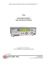 IET Labs 1910 User And Service Manual
-
 Hantek 1832C User manual
-
 Itm 885 Operating instructions
-
Aktakom AMM-3320 User manual
-
 China Electronics Technology Instruments AV3672 Series User manual
-
Megger MOM2 User manual
-
Gossen MetraWatt METRAHIT IM XTRA Operating instructions
-
Tegam 3550 User manual
-
 Microtest 6378 User manual
-
 Microtest 6630E User manual


