
gvrSX™ Conversion Instructions
&
System Manual
040-0050-01 Rev A
! Read this manual before installing the Game.
! Keep this manual with the machine at all times.
www.globalvr.com
service.globalvr.com
408.597.3400
© 2004 GLOBAL VR, INC. All Rights Reserved
Operation Blockade, Infogrames and the Infogrames logo are trademarks of Infogrames Entertainment. S.A. Beach Head 2000, Beach Head
2002, and Beach Head 2003: Desert War are trademarks of Digital Fusion Inc and are used under license by Infogrames.
All other trademarks are the property of their respective owners.

Preface
GVR SX Conversion System Manual
Page 2 of 48 040-0050-01 Rev. A 10/29/2004
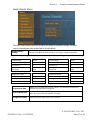
Table of Contents
Preface .......................................................3
Safety ...........................................................3
Warnings ...................................................3
Environmental Conditions........................3
FCC Notices (United States).....................4
Section 1 – Game Description .....................5
Section 2 – Cabinet Conversion...................6
Upgrade Steps..............................................6
Clean and Prepare the Cabinet.....................6
Remove old Tournament Header
and Card Reader.....................................7
Conversion Kit Contents and
Replacement Parts List ..........................8
Replace the Monitor (Optional).................10
Remove the Old Monitor........................10
Adapt the Cabinet for the Larger
Monitor ................................................10
Install the New Monitor..........................12
Install the Cabinet Exhaust Fan .................13
Set Up the Hardware..................................15
Set Up AC Power Distribution................15
Remove the Game PCB and Install
New Hardware.....................................16
Connect the Jamma Conversion
Board and UVC....................................17
Install the Happ UGCI Board .................18
Set Up the Computer...............................19
Connect the Computer ............................20
Secure the Computer...............................21
Upgrade the Control Panel.........................22
Prepare the Control Panel .......................22
Apply Control Panel Graphics................22
Install Buttons and Connect Wiring........23
Apply the Cabinet Graphics and
Marquee Artwork.................................24
Apply the Serial Number Sticker............25
Section 3 – Power ON and Test the
Cabinet .....................................................26
Run the Joystick Calibration Utility ..........26
Adjust the Universal Video
Converter (UVC) .................................27
Section 4 – Using the Game Operator
Menu .....................................................28
Setting Game Options and Resets..............28
Machine Menu...........................................29
Game Mode Menu .....................................30
Game Resets Menu....................................31
Coin Audits ................................................32
Game Purchase Audit.................................32
Game Selection..........................................33
Player Control Test.....................................33
Monitor Calibration Test............................34
Section 5 – Starting a Game.......................35
Playing a Beach Head Game......................36
USB Game Dongles...................................37
Section 6 – System Software CDs.............38
Operating System Restore CD...................38
Game Software CDs ..................................38
Section 7 – Troubleshooting ......................39
Section 8 – Diagrams and Schematics.......43
Computer Rear Panel Diagram..................45
Warranty Service........................................46
Warranty Information..............................46
Technical Support ......................................48
Table of Figures
Figure 1. Drilling Cabinet Air Holes.............13
Figure 2. Typical Jamma Conversion
Board and UVC Connections...............17
Figure 3. Happ UGCI Board
Connections..........................................18
Figure 4. Finished Control Panel...................22
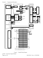
Figure 5. Simplified Wiring Diagram...........43
Figure 6. Detailed Wiring Diagram...............44
Figure 7. Computer Rear Panel
Diagram................................................45

Preface
© 2004 GLOBAL VR
®
, INC.
040-0050-01 Rev. A 10/29/2004 Page 3 of 48
Preface
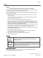
Safety
Please read this page before preparing your arcade cabinet for game play.
The following safety instructions apply to all game operators and service personnel. Specific
warnings and cautions will be included throughout this manual.
Use the following safety guidelines to help protect the system from potential damage and to
ensure your personal safety:
• Make sure that the switch on the back of the computer is set to match the AC power in
use at your location:
115 volts / 60Hz in most of North and South America and some Far Eastern countries
such as Japan, South Korea and Taiwan
230 volts / 50Hz in most of Europe, the Middle East and the Far East
• To help prevent electric shock, plug the system into a properly grounded power source.
The cables are equipped with 3-prong plugs to help ensure proper grounding. Do not use
adapter plugs or remove the grounding prong from a cable. If you must use an extension
cable, use a 3-wire cable with properly grounded plugs.
• To help protect your system from sudden increases and decreases in electrical power, use
a surge suppressor, line conditioner, or Uninterruptible Power Supply (UPS).
• Be sure nothing rests on the system's cables and that the cables are not located where they
can be stepped on or tripped over.
• Do not spill food or liquid on the cabinet.
• Do not push any objects into the openings of the system—doing so can cause fire or
electric shock by shorting out interior components.
• Keep your system far away from radiators and other heat sources.
• Do not block cooling vents.
Warnings
To avoid electrical shock, unplug the cabinet before performing the
installation procedures.
GLOBAL VR
®
assumes no liability for any damages or injuries incurred while
setting up or servicing the cabinet. Only qualified service personnel should
perform installation or service procedures!
Environmental Conditions
Cabinet is intended for indoor use only. Be sure to keep the cabinet dry and maintain
operating temperatures of 10°-40°C (50°-104°F).

Preface
gvrSX™ Conversion System Manual
Page 4 of 48 040-0050-01 Rev. A 10/29/2004
FCC Notices (United States)
Electromagnetic Interference (EMI) is any signal or emission radiated in free space or
conducted along power or signal leads, that endangers the functioning of radio navigation or
other safety service, or that seriously degrades, obstructs, or repeatedly interrupts a licensed
radio communications service. Radio communications services include, but are not limited
to, AM/FM commercial broadcast, television, cellular services, radar, air-traffic control,
pager, and Personal Communication Services (PCS). These licensed services, along with
unintentional radiators such as digital devices (including computer systems) contribute to the
electromagnetic environment.
Electromagnetic Compatibility (EMC) is the ability of items of electronic equipment to
function properly together in the electronic environment. While this computer system has
been designed and determined to be compliant with regulatory agency limits for EMI, there
is no guarantee that interference will not occur in a particular installation. If this equipment
does cause interference with radio communications services, which can be determined by
turning the equipment off and on, you are encouraged to try to correct the interference by one
or more of the following measures:
• Re-orient the receiving antenna.
• Relocate the cabinet relative to the receiver.
• Plug the game into a different outlet so that the computer and the receiver are on different
branch circuits.
If necessary, consult a Regulatory EMC representative of GLOBAL VR
®
or an experienced
radio/television technician for additional suggestions. You may find the FCC Interference
Handbook, to be helpful. It is available from the U.S. Government Print Office, Washington,
DC 20402.
This device has been tested and complies with the limits for a Class A digital device pursuant
to Part 15 of the FCC Rules. These limits are designed to provide reasonable protection
against harmful interference when the equipment is operated in a commercial environment.
This equipment generates, uses, and can radiate radio frequency energy. If not installed and
used in accordance with the instruction manual, it may cause harmful interference with radio
communications. Operation of this equipment in a residential area is likely to cause harmful
interference, in which case you will be required to correct the interference at your own
expense.
Operation is subject to the following conditions:
• This device may not cause harmful interference.
• This device must accept any interference received, including interference that may cause
undesired operation.

Section 1 – Game Description
© 2004 GLOBAL VR
®
, INC.
040-0050-01 Rev. A 10/29/2004 Page 5 of 48
Section 1 – Game Description
The GLOBAL VR
®
gvrSX™ Conversion Kit lets operators convert old Jamma cabinets for
the same game play as the GLOBAL VR
®
Vortek cabinet. The Conversion Kit uses the
existing cabinet, coin inputs, speakers, and Jamma harness.
The gvrSX™ design showcases the following features:
• Superior graphics.
• Easily upgradeable with exciting new game software.
• Four real motion axes: yaw (turn) left/right rotation, and pitch (tilt) up/down.
The conversion kit utilizes a state-of-the-art PC-based interactive visual computing system.
The GLOBAL VR
®
Multi-Game software shell allows multiple games to be installed and
played on one cabinet at any time. This PC-based configuration provides the advantage of
follow-on periodic new game releases for the cabinet, and the ability to accommodate
virtually any new, future 3D PC game that would be enhanced by the addition of motion
control for the Arcade Industry.
gvrSX™ provides the following benefits to operators:
• Consistent earnings from proven game operators for all generations.
• Multi-Game Shell. Upgrade and install new games for the gvrSX™ platform at any time.
Players can choose from multiple games on one cabinet.
• Multiple games are available for each cabinet, including the top earners: Beach Head
2000, Beach Head 2002, and Beach Head 2003: Desert War, with regular new releases.
• Superior reliability.

Section 2 – Cabinet Conversion
gvrSX™ Conversion System Manual
Page 6 of 48 040-0050-01 Rev. A 10/29/2004
Section 2 – Cabinet Conversion
Converting your cabinet consists of the primary steps listed below. Exact steps may vary
depending on your cabinet.
Upgrade Steps
• Clean and Prepare your Cabinet: Remove all graphics and labels, tournament header,
and card reader, and clean the cabinet (page 6).
• Install the New Monitor: Do this if you purchased the monitor upgrade kit with the 27-
inch monitor (page 10). Otherwise, you will install the Universal Video Converter
(UVC) card to adapt the existing monitor to work with the new hardware.
• Install the Fan and Drill Ventilation Holes: Improve cabinet cooling to accommodate
the new computer (page 13).
• Set Up the Hardware: Install the new computer, UGCI Board, Jamma Conversion
Board, and UVC (if used) and make all connections (page 17).
• Upgrade the Control Panel: Upgrade your control panel with the new controls and
artwork (page 22).
• Apply the Cabinet Graphics: Install the new cabinet graphics and labels (page 27).
Clean and Prepare the Cabinet
GLOBAL VR
®
requires that all converted cabinets meet the guidelines for finished cabinet
artwork described in this instruction manual.
You must remove all previous artwork, serial numbers, and labels from the cabinet before
installing the gvrSX™ artwork. Make sure the new cabinet artwork is setup as instructed in
this manual. Clean the cabinet well so that the new graphics will adhere properly.

Section 2 – Cabinet Conversion
© 2004 GLOBAL VR
®
, INC.
040-0050-01 Rev. A 10/29/2004 Page 7 of 48
Remove old Tournament Header and Card Reader
If your cabinet has an existing tournament header or card reader, these components can be
removed. They are not used by the gvrSX™ system.
The card reader is usually located near the coin door. The header is usually located at the top
of the cabinet. Perform the following steps to remove the card reader and tournament header:
1. Unplug the data cables from the card reader and remove them from the cabinet.
2. Un-bolt the card reader and use the same carriage bolts to install a card reader blank plate
(not provided).
3. Unplug the cables from the tournament header and remove them from the cabinet.
4. Un-bolt the tournament header and remove it from the cabinet.

Section 2 – Cabinet Conversion
gvrSX™ Conversion System Manual
Page 8 of 48 040-0050-01 Rev. A 10/29/2004
Conversion Kit Contents and Replacement Parts List
Table 1. Conversion Kit Components
Electronic Components
Description Qty Part Number
System Computer (Not Shown) 1
DFI-CS35-TL-
GVRSX
UGCI board, HAPP Flying 1 95-0800-20
Joystick, Pup, Analog with Atari Grips 1 95-0923-GVR
White Pushbutton W/ Micro Switch 4 47-9150-02
JAMMA Conversion Board 1 990-0007-01
Universal Video Converter (UVC) Card 1 96-0583-00
DONGLE, USB, KQRTG 1 USB-KQRTG
PS2-Keyboard (Not Shown) 1 PS2-KEYBOARD
7-Outlet Power Strip with Surge
Protector (Not Shown)
1 49-0963-40
Cables & Miscellaneous Hardware
Description Qty Part Number
Cable, UVC to JAMMA 1 115-0018-01
Cable, UGCI Coin & Op to JVC Coin &
Op (Not Shown)
1 115-0062-01
Cable, VGA, 6 foot, M/M 1 V-0606
Cable, USB 2 USB-AB06MM
Cable, PC Y-Power 1
PGAK-FLT-3500-08
Cable, Coin Harness Assy (Not Shown) 1 95-0002-014
Cable, 3.5mm Audio, 6Ft 1 96-0539-00
Standoff, 3" tall .156 hole Screw-Down
(For UVC and Jamma Board)
8 LCBS-L-5-01
PCB Mounting Feet Set of 4
(for UGCI Board)
1 49-1019-00
Button Plug (Black) 1 52-6212-00
DFI Computer Mount (Not Shown) 2 V2-0183-00
#10 x 1/2" Course-Thread Wood Screw 4 10N50PPAZZ
1/4-20 x 3/4" Phillips Pan Screw 2 25C37PPMZZ
6-32 X 1/2 Pan-Head Wood Screw 8 4600-0032
1/4-20 Nylon Lock Hex Nut 2 4600-0033
18AWG Butt Connector 3 PGAK-2A0701
#8 Hole 18 AWG Ground Ring 1 PGAK-5A890
18AWG .250 Spade 2 PGAK-KTN50

Section 2 – Cabinet Conversion
© 2004 GLOBAL VR
®
, INC.
040-0050-01 Rev. A 10/29/2004 Page 9 of 48
CDs, Labels, and Manuals
Description Qty Part Number
Conversion Instructions & System Manual (This
Document)
1 040-0050-01
Document, Software Restore 1 040-0060-01
Software, Game, Beach Head 2003: Desert War
1 050-0040-01 1
Software, Game, Beach Head 2000 1 050-0016-01 1
Software, Game, Beach Head 2002 1 050-0017-01 1
Software, V3 and gvrSX™ Recovery Disk XP
Home, Multi Game Upgrade
1 050-0019-01 1
Software, Joystick Calibration Utility CD 1 050-0022-01
Serial Number Label 1 L-0039
Microsoft Windows XP, Home 1 WINXP-HOME
Artwork
Description Qty Part Number
Side Decal 2 SX-AW-09
Marquee Artwork 1 SX-AW-08
Control Panel Background Artwork 1 SX-AW-07
FIRE Decal 2 SX-AW-01
CANNON Decal 2 SX-AW-02
MISSILES Decal 2 SX-AW-03
GVR Console Logo 1 SX-AW--4
Joystick Decal 1 SX-AW-06
Console Logo 1 SX-AW-05
Table 2. Optional Monitor Upgrade Kit Components (Part #: PGA-UPGRADE-MTR)
Description Qty Part Number
DOC, Instructions for relocating mounting holes 1 040-0045-01
1/4 X 1.0 Carriage Bolt, Stl/Znc 4 4600-0013
1/4" Flat Washer SAE Stl/Znc 4 4600-0014
Nut, 1/4-20 Kepnut Stl/Znc 4 4600-0015
Monitor Bezel 28" 1 49-0106-01
Monitor, Wells-Gardner 27" SVGA 1 WGM2792-UOTS19C-MOD
Template, Monitor Bracket Mounting Holes 1 L-0059

Section 2 – Cabinet Conversion
gvrSX™ Conversion System Manual
Page 10 of 48 040-0050-01 Rev. A 10/29/2004
Replace the Monitor (Optional)
Note: Do Not use the Universal Video Controller (UVC) board with the Wells Gardner
®
monitor.
If you have the Monitor Upgrade Kit, perform the steps in this section to remove the old
monitor and install the 27-inch Wells-Gardner
®
monitor.
Remove the Old Monitor
1. Open the service shelf, and remove the glass display shield and monitor bezel.
2. Disconnect ALL wiring from the back of the monitor. Make sure that no wires still
connected to the monitor are tied to the cabinet.
3. Remove the four (4) monitor retaining nuts and washers and save them for reinstallation.
4. Remove the monitor from the cabinet. It is advisable to have at least two people to
support the weight of the monitor.
5. Proceed to the next section and install the new monitor.
Adapt the Cabinet for the Larger Monitor
If your cabinet already had a 27-inch monitor, you should be able to proceed to the next
section and install the monitor.
If your cabinet had a 25-inch monitor, refer to the figure that follows, and perform the
following steps to adapt the cabinet hardware for the larger, 27-inch Wells-Gardner
®
monitor:
1. Note the positioning of the lower monitor bracket to aid in reinstallation. Remove the
nuts and bolts that secure the lower monitor bracket to the cabinet. Remove the bracket
and save it for reinstallation. Perform the following steps to drill new bolt holes for the
bracket to relocate it for the larger monitor.
2. Refer to the figure below and mark straight lines, as shown, through the center of the two
sets of bolt holes and about 2" below. Drill two ¼" diameter bolt holes 1-7/16" below the
original holes, and along the same centerline. Use the template from the kit (part #:
L-0059) to aid in placing the holes.
3. The overall distance between the bolt heads on the side of the cabinet must be 20-3/4"
center-to-center in the long direction, and 1-9/16" center-to-center in the short direction.

Section 2 – Cabinet Conversion
© 2004 GLOBAL VR
®
, INC.
040-0050-01 Rev. A 10/29/2004 Page 11 of 48
4. Repeat the previous two steps to drill bolt holes in the other side of the cabinet.
5. Align the lower monitor bracket with the new bolt holes and bolt it in place using the nuts
and bolts removed previously.
6. Install the four (4) supplied carriage bolts into the original bolt holes to give them a
finished appearance.

Section 2 – Cabinet Conversion
gvrSX™ Conversion System Manual
Page 12 of 48 040-0050-01 Rev. A 10/29/2004
Install the New Monitor
1. Refer to the picture below and make sure that the monitor frame of the new 27-inch
Wells-Gardner
®
Monitor has the holes required to mount it to the cabinet brackets. Both
the top and bottom sections of the frame must have two pairs of holes (some monitor
frames have only one pair of holes in each section). The inside pair of holes must be
centered on the bracket, and measure 19-1/4" center-to-center.
2. If the monitor frame does not have the required holes, drill them in both the top and
bottom frame sections as follows: Drill two (2) 3/8" diameter holes, centered, 19-1/4"
apart. Each of these new holes should be approximately 11/16" inboard from the existing
holes, and on the same horizontal centerline.
Caution: Avoid getting drill chips in the electronic components.
CAUTION: The monitor is very heavy. Monitor installation requires at least two
people. It is best to have a third person handling the monitor frame from inside the
cabinet back door. It is easy to catch fingers between the monitor frame and cabinet.
3. To install the monitor, first install the lower edge of the monitor onto the lower bracket
studs, and then rotate the monitor downwards to catch on the upper bracket studs. This
will require at least two people. It may be best to have a third person handling the
monitor frame from inside the back door. Watch your fingers; this monitor is very heavy.

Section 2 – Cabinet Conversion
© 2004 GLOBAL VR
®
, INC.
040-0050-01 Rev. A 10/29/2004 Page 13 of 48
4. Use the old hardware to re-attach the monitor to the cabinet bracket (four places).
5. Install the new monitor bezel.
6. Clean and replace the glass display shield.
7. Replace the small retainer tab that secures the display shield in place.
8. Mount the monitor remote control board in a convenient location in the service tray.
9. Connect the monitor ground wire to a ground lug on the cabinet.
10. If the old monitor was powered with an AC isolation transformer, remove the transformer
from the cabinet. The new monitor will connect directly to the AC power strip, to be
installed in the next section.
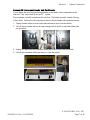
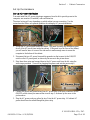
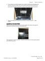
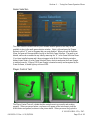
Install the Cabinet Exhaust Fan
An exhaust fan is required to keep the temperature inside the cabinet cool enough for the
computer to operate properly.
If you experience blank screens or rebooting issues, this could be due to excessively high
temperatures inside the cabinet. Drilling more air holes in the lower rear of the cabinet, as
described in step 1 below, should improve airflow and reduce cabinet temperatures.
Perform the following steps to install the exhaust fan and drill air holes:
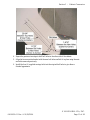
1. Using a 1/2" drill bit, drill six to eight air holes in the lower rear of the cabinet, as shown
in Figure 1. Be careful not to damage any wires or components while drilling.
6-8 1/2" Air Holes
Place low in cabinet. Position so as to
avoid drilling into wires or components.
Figure 1. Drilling Cabinet Air Holes
2. Using a screwdriver, remove the metal or plastic grill covers that cover the ventilation
slots on the back of your cabinet. Push in on each corner of the metal grill and they will
pop out and fall to the bottom of the cabinet.

Section 2 – Cabinet Conversion
gvrSX™ Conversion System Manual
Page 14 of 48 040-0050-01 Rev. A 10/29/2004
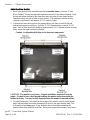
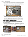
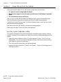
3. Install the exhaust fan behind the ventilation slot, just above the rear cabinet door, as
shown by the arrow in the picture below.
4. Place the exhaust fan on the outside of the ventilation slots and use the mounting holes in
the fan as a template to drill the mounting holes. Use an 11/64" drill bit to drill the four
mounting holes for the exhaust fan.
5. Place the fan on the inside of the cabinet so that it will blow air out of the cabinet. Use
the 8-32 x 2 inch screws with nuts to secure the fan to the cabinet, as shown in the picture
above.
6. Plug the fan into the AC power strip inside the cabinet, and verify that the fan blows air
out of the cabinet.

Section 2 – Cabinet Conversion
© 2004 GLOBAL VR
®
, INC.
040-0050-01 Rev. A 10/29/2004 Page 15 of 48
Set Up the Hardware
Set Up AC Power Distribution
You must install the AC power strip/surge suppressor from the kit to provide power to the
computer, new monitor (if installed), and ventilation fan.
The actual wiring will vary depending on which cabinet you are converting. Use the
instructions that follow as a general guideline for setting up AC power distribution.
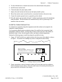
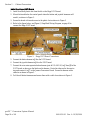
1. Locate the AC power panel inside the cabinet. The panel is usually the distributing point
for all of the AC power lines inside the cabinet. If the panel is on the floor of the cabinet,
you will need to move it to one of the side walls to make enough room to secure the
computer to the bottom of the cabinet.
2. Disconnect the two AC power lines and the ground wire that connect to the ON/OFF
switch on the AC power panel, as shown by the arrows in the picture above.
3. Strip these three wires and connect them to the AC power cord from the kit, using the
wire crimps provided. (You will be plugging this power cord into the power strip.)
4. Connect the power and ground wires from AC power strip to the three connectors on the
ON/OFF switch where you removed the wires in step 2, as shown by the arrow in the
picture above.
5. Plug the AC power cord you spliced in step 3 into the AC power strip. All cabinet AC
power should now be routed through the power strip.

Section 2 – Cabinet Conversion
gvrSX™ Conversion System Manual
Page 16 of 48 040-0050-01 Rev. A 10/29/2004
6. Some older cabinets with CGA monitors have an AC isolation transformer that is used to
power the monitor. These are often bulky, heavy transformers that take up most of the
space on the bottom of the cabinet, and they cannot be removed unless you replace the
monitor. If you connect a monitor that requires an AC isolation transformer directly into
an AC power source, you will damage the PCB chassis on the monitor.
7. If your cabinet has an AC isolation transformer for the monitor, find the AC power lines
that power the AC isolation transformer and splice them to an AC power cord (not
provided in the kit), so you can connect this to the AC power strip. You may need to
reposition the AC isolation transformer to make room to install the computer on the floor
of the cabinet. (Note: The new Wells-Gardner
®
monitors do not use an AC isolation
transformer. If you are installing this monitor, you can safely remove the transformer.)
Remove the Game PCB and Install New Hardware
Caution: Power must be off when connecting boards. To prevent damage from
electrostatic discharge (ESD), handle PCBs by the edges only and use a grounding wrist
strap or similar precaution.
1. The Conversion Kit hardware uses the existing Jamma harness wiring for speakers, video
(for an existing monitor), and coin inputs. Remove the Game PCB and any other
hardware from the old game, but keep the existing DC power supply and Jamma harness
wiring in place.
2. Install four small plastic feet from the kit on the Jamma conversion board, and on the
UVC if you are installing one.

Section 2 – Cabinet Conversion
© 2004 GLOBAL VR
®
, INC.
040-0050-01 Rev. A 10/29/2004 Page 17 of 48
3. Set jumper J8 on the Jamma conversion board to pins 1 and 2 for stereo, or pins 1 and 3
for mono audio, depending on how your cabinet audio is set up.
4. Place the boards next to each other in the service tray where you removed the old boards.
Make sure that the Jamma connector on the Jamma wire harness can reach the Jamma
Conversion Board before securing the boards to the cabinet.
5. Secure the boards with wood screws in the plastic feet.
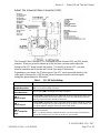
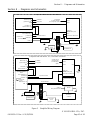
Connect the Jamma Conversion Board and UVC
Figure 2. Typical Jamma Conversion Board and UVC Connections
Refer to the figure above, and Figure 5, Simplified Wiring Diagram, on page 43, and perform
the following steps to connect the Jamma harness wiring and other cables to the Jamma
Conversion Board:
1. Connect the Jamma connector from the Jamma harness to the Jamma edge on the Jamma
Conversion Board.
2. Connect the Video Input, J4 on the Jamma Conversion Board to the video output port on
the Video Converter board, if used, or to the VGA port on the computer video card.
3. Connect the existing PC power supply in the cabinet to the Jamma Conversion Board
PWR IN port using the PC Y-power cable from the kit.
Note: The PC Y-power cable uses a standard PC power supply connection found on
most DC power supplies used in arcade cabinets. If your existing power supply does not
have this type of connector, you will need to splice the Y-Power cable into the power
supply on the cabinet. Here are the specifications for the PC Y-power cable:
• Red Wire +5 VDC
• Yellow Wire +12 VDC
• Black Wire Ground

Section 2 – Cabinet Conversion
gvrSX™ Conversion System Manual
Page 18 of 48 040-0050-01 Rev. A 10/29/2004
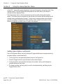
Install the Happ UGCI Board
1. Install four small plastic feet from the kit on the Happ UGCI board.
2. Mount the board below the control panel where the button and joystick harnesses will
reach it, as shown in Figure 3.
3. Secure the board with wood screws in the plastic feet as shown in Figure 3.
4. Refer to the figure below, and Figure 5, Simplified Wiring Diagram, on page 43 to
connect the Happ UGCI board.
Figure 3. Happ UGCI Board Connections
5. Connect the button harness to J4 on the UGCI board.
6. Connect the joystick harness to J6 on the UGCI board.
7. Connect the coin meter operator button harness (part #: 115-0062-01) to J3 and J5 of the
UGCI board, as shown on the labels on the harness. Route the other end to the service
tray and connect it to J7 on the Jamma Conversion Board. Secure the harness with a
cable tie as shown in Figure 3.
8. Coil the old button harnesses and secure them with a cable tie as shown in Figure 3.

Section 2 – Cabinet Conversion
© 2004 GLOBAL VR
®
, INC.
040-0050-01 Rev. A 10/29/2004 Page 19 of 48
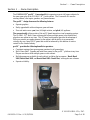
Set Up the Computer
The computer comes pre-loaded with the game software. There is no need to reload the
software with the CDs in the kit. The Software recovery CDs are included in case you have a
software problem in the future or wish to change the specific game titles available.
CAUTION: The computer can be damaged very easily. Use caution when installing
the computer. Avoid touching internal components. These components are susceptible
to Electrostatic Discharge (ESD) damage.
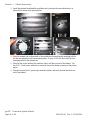
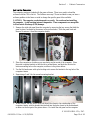
1. Remove the right side panel from the computer by removing the two screws that hold the
panel in place, as shown by the arrows in the picture below. Slide the panel back and
then out to remove it from the computer chassis.
2. Place the computer on its side so you can clearly see the inside of the computer. Place
the metal computer bracket so that the tab is pointed down, and hook the tab into the
bottom mounting hole on the computer, as shown in the picture below.
3. Use the flat-head screw with nylon locking nut to secure the bracket to the top hole of the
computer chassis.
4. Repeat steps 2 and 3 for the second mounting bracket.
5. When finished, the two screws with nuts should be closest to the outside edge of the
computer chassis, with the bracket tabs hooked into the holes closest to the motherboard,
as shown in the last part of the picture above. Re-install the side panel on the computer.

Section 2 – Cabinet Conversion
gvrSX™ Conversion System Manual
Page 20 of 48 040-0050-01 Rev. A 10/29/2004
Connect the Computer
Refer to Figure 7, Computer Rear Panel Diagram, on page 45, and Figure 5, Simplified
Wiring Diagram, on page 44 to make the connections to the computer.
1. Connect the USB hub to one of the computer USB ports and install the game dongles in
the USB hub. Refer to the section titled USB Game Dongles on page 37 for more
information on the dongles and USB hub.
2. Connect the audio cable from the green audio port of the computer to J2 of the Jamma
Conversion Board.
3. Connect the video cable from the computer VGA port to J1 of the UVC (if used) or the
monitor.
4. Connect the USB cable from the computer USB port to the UGCI board.
Important: The USB connector from the UGCI board must be connected directly to the
USB port on the computer, not to the USB hub.
5. Secure the wires to the cabinet so they do not get pinched or torn if the cabinet has a
sliding control panel.
6. Connect the power cord from the computer to the AC power strip.
Page is loading ...
Page is loading ...
Page is loading ...
Page is loading ...
Page is loading ...
Page is loading ...
Page is loading ...
Page is loading ...
Page is loading ...
Page is loading ...
Page is loading ...
Page is loading ...
Page is loading ...
Page is loading ...
Page is loading ...
Page is loading ...
Page is loading ...
Page is loading ...
Page is loading ...
Page is loading ...
Page is loading ...
Page is loading ...
Page is loading ...
Page is loading ...
Page is loading ...
Page is loading ...
Page is loading ...
Page is loading ...
-
 1
1
-
 2
2
-
 3
3
-
 4
4
-
 5
5
-
 6
6
-
 7
7
-
 8
8
-
 9
9
-
 10
10
-
 11
11
-
 12
12
-
 13
13
-
 14
14
-
 15
15
-
 16
16
-
 17
17
-
 18
18
-
 19
19
-
 20
20
-
 21
21
-
 22
22
-
 23
23
-
 24
24
-
 25
25
-
 26
26
-
 27
27
-
 28
28
-
 29
29
-
 30
30
-
 31
31
-
 32
32
-
 33
33
-
 34
34
-
 35
35
-
 36
36
-
 37
37
-
 38
38
-
 39
39
-
 40
40
-
 41
41
-
 42
42
-
 43
43
-
 44
44
-
 45
45
-
 46
46
-
 47
47
-
 48
48


Global VR 040-0050-01 User manual
- Type
- User manual
- This manual is also suitable for
Ask a question and I''ll find the answer in the document
Finding information in a document is now easier with AI
Related papers
Other documents
-
Genius G08XU Owner's manual
-
Climadiff DUOVINO/1 Datasheet
-
 ASA Electronics JE1029BVM User manual
-
 Modecom MC-S300 PFC User manual
-
Honeywell RC-UV-1 User manual
-
Avintage DV315AGN4-2 Datasheet
-
 Creative Arcades 3500 Machine Simple User Manual
-
 Sargent EC480 Installation guide
-
Climadiff CV52IXDZ Datasheet
-
Gardner 5570-1-30 Operating instructions


