
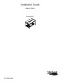
Installation Guide
Island Sink
K-6138, K-6417
1114139-2-A

Thank You For Choosing Kohler Company
Thank you for choosing Kohler Company. Your Kohler Company product reflects the true passion for design,
craftsmanship, artistry, and innovation Kohler Company stands for. We are confident its dependability and
beauty will surpass your highest expectations, satisfying you for years to come.
All the information in this guide is based upon the latest product information available at the time of
publication. At Kohler Company, we strive to fulfill our mission of improving the level of gracious living for
each person who is touched by our products and services. We reserve the right to make changes in product
characteristics, packaging, or availability at any time without notice.
Please take a few minutes to review this guide. If you encounter any installation or performance problems,
please call 1-800-4KOHLER (1-800-456-4537) from within the USA and Canada, or 001-877-680-1310 from
within Mexico.
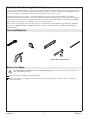
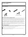
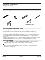
Tools and Materials
Before You Begin
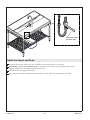
CAUTION: Risk of personal injury or product damage. Large cast iron sinks are very heavy. Get
help when lifting the sink.
Observe all local plumbing and building codes.
Kohler Co. reserves the right to make revisions in the design of products without notice, as specified
in the Price Book.
Socket Wrench With Sockets
1114139-2-A 2 Kohler Co.

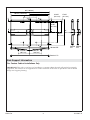
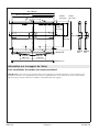
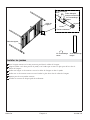
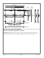
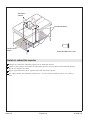
Sink Support Information
For Custom Cabinet Installations Only
IMPORTANT! This sink is very heavy, if installing to a custom cabinet the sink will need to be properly
supported. The locations of all support bosses on the underside of the sink are provided to aid in cabinet
design and support planning.
24-3/8"
(61.9 cm)
B
DA
DA
B
20" (50.8 cm)
15-3/8"
(39.1 cm)
17-3/8"
(44.1 cm)
30-3/4"
(78.1 cm)
18-5/16"
(46.5 cm)
18-5/16"
(46.5 cm)
39"
(99.1 cm)
31-1/2" (80 cm)
63" (160 cm)
58-3/4" (149.2 cm)
Section B-B
Section C-C
Section
A-A
Section
D-D
C
C
Kohler Co. 3 1114139-2-A

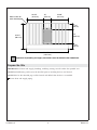
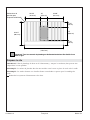
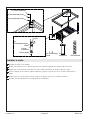
Prepare the Site
IMPORTANT! All drain and supply plumbing, including venting, must fit within the specified area.
NOTE: Finished flooring surface must be installed prior to installing the base and shroud.
NOTE: Holes for the threaded pegs will be located and drilled after the base is assembled.
Locate drain and supply piping.
10"
(25.4 cm)
24-3/8"
(61.9 cm)
24-3/8"
(61.9 cm)
7-7/8"
(20 cm)
7-7/8"
(20 cm)
19"
(48.3 cm)
58-3/4"
(149.2 cm)
34-3/4"
(88.3 cm)
Important! All plumbing and supply connections must be limited to the shaded area.
Holes in floor for
each threaded peg
1114139-2-A 4 Kohler Co.

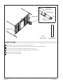
Install the Legs
With the shelf on its side, insert a leg into the shelf collar.
Align the hole at the foot end of the leg with the bottom-most hole in the shelf collar.
Thread a long setscrew through the shelf collar and into the leg.
Thread a short setscrew through the uppermost hole in the shelf collar.
Repeat for remaining three legs.
Install a pad to each leveling foot.
Long Setscrew
Short Setscrew
Long Setscrew
Short
Setscrew
Leveling Foot
Shelf Collar
(cross-section)
Pad
Support Collar
Support Collar
Leg
Kohler Co. 5 1114139-2-A

Install the Frame
Install the frame to the legs.
Loosely thread a hex cap screw into the upper hole of each of the frame collars.
Thread a short setscrew into the two lower holes of each of the frame collars.
Tighten the long setscrew (lower leg) until it is snug against the inside wall of the leg.
Tighten all short setscrews until they are snug against the legs.
Install a threaded peg to each leveling foot.
Hex Cap Screw
Short
Setscrew
Short
Setscrew
Hex Cap Screw
Short
Setscrew
Long Setscrew
Short
Setscrew
Leveling Foot
Threaded Peg
Leg
Threaded Peg
1114139-2-A 6 Kohler Co.

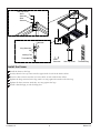
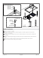
Install and Level the Sink
Move the sink base to its installation location. Mark the location of each foot peg onto the floor.
Using a ¼” drill bit, drill holes at the installation location of each leg.
Move the sink base to its installation location. Verify all the foot pegs seat fully into the holes in the
floor.
CAUTION: Risk of personal injury or product damage. Large cast iron sinks are very heavy. Get
help when lifting the sink.
Align the corner bosses of the sink with each of the legs.
Carefully lower the sink onto the stand.
Tighten the hex cap screws, tightening opposite corners evenly until all are hand tight.
Using the leveling feet, level the sink. Turn the feet clockwise to raise the sink, or counterclockwise
to lower.
Raise
Lower
Kohler Co. 7 1114139-2-A

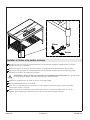
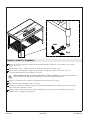
Install the Supports
CAUTION: Risk of product damage. Use care when repositioning the support collars, to avoid
scratching the shelf.
Thread a support rod assembly into each support collar.
Using the coupling nut, adjust the length of the support rod until each clevis reaches a tab on the
underside of the sink.
Secure each clevis to the sink with a bolt, 2 washers, and a nut.
Center each support collar on the shelf and secure with a setscrew.
Using the coupling nuts, tighten each support rod.
1/2" -13 Nut
1/2" x 13 Bolt
View from Underneath
1/2" Washer
Support Rod
Clevis
Support
Collar
Coupling Nut
Tab
1114139-2-A 8 Kohler Co.

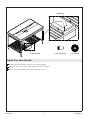
Install the Lower Shroud
Position the lower shroud, tabs up, in the shelf opening.
Align the slots in the sides of the shroud with the shelf posts.
Secure the lower shroud with washers and cap screws.
Cap Screw
Lower Shroud
10-24 Cap Screw
Flat Washer
Flat Washer
Kohler Co. 9 1114139-2-A

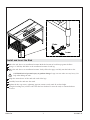
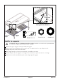
Install the Faucet and Drain
Install the faucet and drain to the sink according to the manufacturer’s instructions.
If installing a faucet with a pullout spray: To minimize noise when using the pullout spray, wrap
the hose weight with the supplied adhesive foam tape.
Make all drain and supply connections.
Run water into the sink and check all connections for leaks. Make any adjustments as needed.
Wrap hose weight
with foam tape.
1114139-2-A 10 Kohler Co.

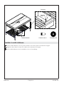
Install the Upper Shroud
Position one half of the upper shroud onto the lower shroud.
Align the two holes in the side of the upper shroud with the tabs of the lower shroud; secure with
the cap screws.
Repeat for the second half of the upper shroud.
Secure both halves of the upper shroud to each other with two cap screws in both the front and
back.
1/4-20 Cap Screw
Cap Screws
Cap Screws
Upper Shroud
Kohler Co. 11 1114139-2-A
Page is loading ...
Page is loading ...
Page is loading ...
Page is loading ...
Page is loading ...
Page is loading ...
Page is loading ...
Page is loading ...
Page is loading ...
Page is loading ...
Page is loading ...
Page is loading ...
Page is loading ...
Page is loading ...
Page is loading ...
Page is loading ...
Page is loading ...
Page is loading ...
Page is loading ...
Page is loading ...
Page is loading ...
-
 1
1
-
 2
2
-
 3
3
-
 4
4
-
 5
5
-
 6
6
-
 7
7
-
 8
8
-
 9
9
-
 10
10
-
 11
11
-
 12
12
-
 13
13
-
 14
14
-
 15
15
-
 16
16
-
 17
17
-
 18
18
-
 19
19
-
 20
20
-
 21
21
-
 22
22
-
 23
23
-
 24
24
-
 25
25
-
 26
26
-
 27
27
-
 28
28
-
 29
29
-
 30
30
-
 31
31
-
 32
32


Kohler K-T16178-4-BV Installation guide
- Type
- Installation guide
- This manual is also suitable for
Ask a question and I''ll find the answer in the document
Finding information in a document is now easier with AI
in other languages
Related papers
-
Kohler K-3374-3-NA Installation guide
-
-
Kohler K-6486-G9 Installation guide
-
Kohler K-5826-K4 User manual
-
Kohler K-6489-FT Installation guide
-
-
-
Kohler K-6488-58 Installation guide
-
-

