Page is loading ...

T3403EN
rev.0204
Stadio Plus
Instructions manual
Audio and Video
door entry system
digital installation
with coded panel
Golmar se reserva el derecho a cualquier modificación sin previo aviso.
Golmar se réserve le droit de toute modification sans préavis.
Golmar reserves the right to make any modifications without prior notice.
golmar@golmar.es
www.golmar.es

1INTRODUCTION
Introduction..........................................1
Index ...................................................1
System characteristics ............................2
Starting recommendations......................2
System operation...................................3
Door panel installation.............................
Embedding box positioning............4 to 5
Door panel fixing and wiring...........5 to 6
Door panel settings .......................7 to 8
EL560 optional module .......................8
Memory banks....................................8
Computer connection..........................8
Final adjustments ................................9
Door panel programming.........................
Programming menues ................10 a 19
Repertory text writing..........................20
Fast repertory search .........................20
Power supply installation.......................21
Lock release installation .......................21
Platea Plus monitor ..................................
Description ......................................22
Function push buttons........................23
EL561 module..................................24
End of line resistor .............................24
Front film replacement.......................24
Monitor connector description............25
Monitor installation ...........................26
Programming...................................27
T-940 Plus telephone ...............................
Description ......................................28
Function push buttons........................28
Telephone installation........................29
Programming...................................30
Installation diagrams ...............................
Connection of an a.c. lock release.......31
Link of several power supplies .............31
Video installation with coaxial.....32 to 33
Video installation w/o coaxial .....34 to 35
Audio installation......................36 to 37
General entrance installation .....38 to 41
Optional connections..............................
External lock release activation ...........42
Auxiliary devices activation.................42
Intercom function..............................43
TV connection ..................................43
2nd camera activation.......................44
Door bell push button connection........44
Troubleshooting hints...........................45
INDEX
First of all we would like to thank and congratulate you for the purchase of this product
manufactured by Golmar.
The commitment to reach the satisfaction of our customers is stated through the ISO-9001
certification and for the manufacturing of products like this one.
Its advanced technology and exacting quality control will do that customers and users enjoy with
the legion of features this system offers. To obtain the maximum profit of these features and a properly
wired installation, we kindly recommend you to expend a few minutes of your time to read this manual.

SYSTEM OPERATION
SYSTEM CHARACTERISTICS
UPDATED FEATURES FROM 5.00 VERSION
STARTING RECOMMENDATIONS
OManagement of up to 255 internal buildings of 1,000 apartments each.
ONew programming menu structure.
ODirect Call Code that allows to use a different call code from the one recorded on the monitor or
telephone (page 12).
O'Repertory:insert' function, that allows to keep sorted the repertory content (page 18).
OTransmission of the repertory content to other panels or porter's exchanges through the
installation wires (page 19).
OThird access control code with time restriction (page 16).
OText edition using the keypad as a mobile phone (page 20).
OPrevious software versions are fully compatible, except when the Direct Call Code is
activated or the number of internal buildings is bigger than 99.
One building systems.
OTo make a call, the visitor should key-in the three digits code corresponding to the apartment he
wishes to contact: the door panel display will show the sequence keyed-in. Once the code has
been introduced, press bell key to confirm the call: acoustic tones will be heard confirming the call
is in progress and the door panel display will show the message calling. At this moment the
call will be received at the monitor (telephone) in the dwelling. If an incorrect code has been
keyed-in, press CANCEL key and try again.
In systems with several access doors, the other(s) door panel(s) will be automatically disconnected:
if a visitor tries to call from other door panel an acoustic tone will be heard confirming the system
is busy and the door panel display will show the message busy.
The call tone will be reproduced on the monitor during 3 seconds: after this time the picture will
appear on the master monitor without the visitor being aware of this. To see the picture in a slave
monitor press the push button, dissapearing the picture on the other monitor. If the call is not
answered in 45 seconds, the system will be freed.
OTo establish communication pick up the monitor (telephone) handset. The communication will last for
one and a half minutes or until the handset is replaced. During the communication the door panel
display will show the message communication. Once the communication has finished the
system will be freed.
OTo open the door, press the door release push button during call or communication progresses: with
one press, the door release operates during the programmed time. During the lock release
activation an acoustic tone will be heard on the door panel confirming the lock release is
activated, and the door panel display will show the message door opened.
OThe monitor and telephone push buttons description is shown on pages 23 and 28 respectively.
Systems with general entrance door panel(s) and several internal buildings.
OTo make a call from a general entrance door panel, the visitor should key-in the five digits code
corresponding to the apartment building he wishes to contact: the door panel display will show the
sequence keyed-in. Proceed as described on the previous paragraph to establish the call progress.
The corresponding internal door panel and the other general entrance door panels (if exist): if a
visitor tries to call an acoustic tone will be heard confirming the system is busy, and the door panel
display will show the message busy. The rest of door panels are free to establish communication.
OTo make a call from an internal door panel proceed as described on the previous paragraph. The
rest of internal door panels are free to establish communication. A call from the general
entrance door panel can be made to any of the internal buildings, except to the one is in
communication.
Use of the repertory names.
OIf the visitor don't know the code of the apartment he wishes to contact, he could find it on the
repertory name by searching through the arrow keys. Once the code has been found, the call can
be made by pressing the bell key. Refer to page 20 for details about fast repertory searching.
Lock release activation using the access control.
OTo open the door using the access control facility, press KEY symbol and one of the valid access
codes. During the lock release activation an acoustic tone will be heard on the door panel
confirming the lock release is activated, and the door panel display will show the message
door opened. If an incorrect code has been keyed-in, press CANCEL key and try
again. The introduction of three wrong consecutive codes freezes the access control during 60
seconds.
23
O
O
O
O
O
Do not use excessive force when tightening the power supply connector screws.
Install the equipment without the power connected. Disconnect from power before any system
modification. Check that the input voltage is lower than 230Va.c.
Before to connect the system, check the connections between door panel, monitors and
telephones, and the transformer connection. Do always follow the enclosed information.
Each time the power supply is restarted, or after a modification, the system will remain blocked
during 30 seconds.
Always use RG-59 or RG-11 coaxial cables. Never use coaxial antenna cable. In installations
no longers than 100m., Golmar RAP-5130 cable can be used.
OMicroprocessed systems with bus installation (no call wires):
wAudio system with 4 common wires installation.
wVideo system with 3 common wires plus coaxial cable.
wVideo system with 4 common wires plus twisted pair cable.
OUnlimited number of door panels being not necessary the use of switching units.
Acoustic busy channel and call acknowledgement signals.
d.c. lock releases activation.
Timed door open activation.
In Platea Plus monitors or T-940 Plus telephones:
Privacy on audio and video communications.
'Video-Spy' function remaining the communication channel free.
Intercommunication function with other monitor or telephone of the same apartment.
Input for door bell apartment push button.
Different call reception tones depending where the call is comming from: main or slave door
panels, door bell push button, intercom, ...
Activation of two auxiliary devices: secondary telecamera, courtesy light, ...
Up to three monitors or telephones in the same apartment without additional power supplies.
O
O
O
O
w
w
w
w
w
w
w

45
DOOR PANEL INSTALLATION
mbedding box positioning.
E
1650
1850
1450
The upper part of the door panel should be placed at 1,65m. height roughly. The hole dimensions
will depend on the number of door panel modules.
The door panel has been designed to be placed under most of the environmental conditions.
However it's recommended to take additional cautions like rainproof covers. To obtain
a good quality picture on video door entry systems, avoid direct incidence from light sources.
reparing the cables entry.
P
Break the bottom flange to pass the cables through. In case of door panels
with more than one embedding box, break the side flanges and
attach the embedding boxes using UC junctions.
1
CE610
125
140
56
Modules
Model
W
H
D
2
CE620
125
257
56
3
CE630
125 mm.
374 mm.
56 mm.
DOOR PANEL INSTALLATION
lace the embedding box.
P
Pass the wiring through the hole made in the bottom part
of the embedding box. Level and flush the embedding
box. Once the embedding box is placed, remove the
protective labels from the attaching door panel holes.
ssembly the door panel modules.
A
Insert the header DOWN marked in the lower module and fix it by screwing the module
shafts.
Place the module spacer between lower and next modules, assuring that the spacer
adjustment notches are inside the panel. Fix the module by screwing the shafts.
Repeat this procedure in case of door panels with one more module (the maximum
number of modules placed vertically is three).
Insert the header UP marked in the last module and fix it by screwing the supplied screws.

67
DOOR PANEL INSTALLATION DOOR PANEL INSTALLATION
Enabled. Disabled.
Coaxial. Twisted pair.
Maximum. Minimum.
Reset. Standby.
ssembly the sound module.
A
Insert the sound module in the grille module.
For a proper assembly, align the light
push button and the microphone rubber
of the sound module with its corresponding
holes in the grille module.
Link the sound module with the keypad module
by using the supplied flat cable.
Select a direction to open the door panel; this selection should ease
the door panel wiring.
The opening direction will be settled through the hinges position,
that must be passed through the header clips as shown.
For example, if the hinges are placed on both clips of the lower
header, the door panel will open downwards; if they are placed
on the right clips of both headers, the door panel will open to left.
To hold the door panel on the embedding box,
insert the hinges in the embedding box lockers
as shown.
old the door panel on the embedding box.
HJumper JP1 loads the installation with a communications
resistor. For a proper system operation, activate this resistor
only in the closest door panel to the backbone installation
or in the general entrance door panel (if exists).
Factory default: enabled.
Jumper JP2 selects the type of cable to be used for the video
signal: coaxial cable (RG-59 or RG-11) or twisted pair.
Twisted pair video transmission requires the use of an
EL560 module plugged in the CN4 connector.
Factory default: coaxial cable.
Jumper JP3 selects the volume of the door panel acknowledgement
signals (call in progress, system busy and door opened).
If after starting the system it's considered that the volume is too
high, modify the jumper position.
Factory default: maximum.
Jumper JP4 allows to reset the installer PIN code to the factory
default (see page 10).
Use this function only in case to forget this code.
With the system switched on, change the jumper position
to reset the code and return it to the standby position.
escription of the configuration jumpers.
D
The JP1, JP2, JP3 and JP4 configuration jumpers
are placed on the left side of the terminal connector.

The door panel has two memory banks
to plug 256Kb memory modules in.
Each module allows to record the custom
text for a maximum of 1000 users.
The system is delivered with one memory module
placed in the bank number 0 (BK0), where
the system configuration will be recorded.
IMPORTANT: in case of door panels with two memory modules,
don't change their bank position once they have been recorded.
BK0 bank module must always have a memory module plugged in.
IMPORTANT:
IMPORTANT:
nformative module lamps wiring.
I
BK0 BK1
9
8
DOOR PANEL INSTALLATION DOOR PANEL INSTALLATION
ptional. EL560 module for video installations
Owith twisted pair cable.
Plug the EL560 module in the CN6 connector.
The CN4 connector is accessible by unbolting
the four screws of the pcb protection cover.
NOTE: on this type of installations the EL561 module
must be plugged in all the monitors.
Refer to the specific installation diagram.
emory banks.
M
omputer connection.
C
It's possible to program the door panel using a
computer through its RS-232C port.
An interface (not included) should be connected
to CN8 door panel connector. MEMEDIT software
(included with the interface) will allow to program
the door panel and to save a copy of each system.
In case of memory damage it will be possible
to restore the system configuration from the computer.
inal adjustments.
F
If after starting the system it's considered that the audio
volume isn't correct, proceed with the necessary
adjustments as shown.
The telecamera has a pan and tilt mechanism built in
to adjust the telecamera position.
In case of low light conditions, an external illumination
can be activated by connecting a R-3 relay
between terminals '+H' and 'L2' of the sound module.
lose the door panel.
C
Fix the door panel by using the supplied
screws.
Finish the door panel assembly by pressing
the closing heads.
Once the informative labels are placed, wire the
lamps from different modules and connect them
to terminals L1 and L2 of the sound module.

10 DOOR PANEL PROGRAMMING
11
DOOR PANEL PROGRAMMING
rogramming menu.
P
golmar 16:30
Access control options can be changed on
this menu. Press OK to enter into this menu.
access control
This menu allows to fill the repertory and
to change its options.
Press OK to enter into this menu.
repertory
Continue
pin code pin:____ 15or
31 1 1
11
On this menu the system configuration options
can be changed.
Press OK to enter into this menu.
configuration
*
O.K. ANCEL
C
onfiguration menu.
C
Continue
Coming from previous page
configuration
:000
panel address
modify value
:000
O.K.
:015
panel address
*
yes
general panel
*
yes
master panel
*
english
yes
panel w. camera
*
To enter into configuration menu, follow
the steps described on the previous page
and press OK when the display shows the
message CONFIGURAtION.
O.K.
O.K.
5
10
It will be necessary to enter into the programming menu to configure the system properties.
For a proper system operation, the menus marked with an asterisk must be configurated.
Two different programming menues are available: installer, that allows to modifiy any of the
system properties and user, that only allows changes that do not affect the system operation.
Programming options with black text and white background are availables in both menues;
options with white text and black background are only availables on installer menu.
The first time you enter into the programming menu, the display messages will appear in spanish.
Press OK when the display shows the message configuracion: the display will show now
castellano. Press OK to change to english or till the desired language appears.
If the option Direct Call Code (page 12) is disabled, it will not be necessary to fill the repertory
name for a proper system operation.
Use the arrow keys to move through the programming menu. Option changes will be validate
by pressing OK key, even if CANCEL key is pressed later.
Use CANCEL key to exit from the configuration menu. The door panel will automatically exit
from the configuration menu after 90 seconds with no operation.
To enter into the main programming menu,
press key symbol and enter
the installer PIN code (factory default: 1315)
or the user PIN code (factory default: 1111).
Allows to choose the language of the displayed
messages and the programming menues.
To choose a different language press OK
until the desired language will be displayed.
Each system must have one master panel only;
the rest of panels must be slave.
In systems with general entrance panel
configure as master one panel of each
internal building.
Press OK to change this value.
If this panel is a general entrance door panel
select YES.
Press OK to change this value.
Sets the building code. In buildings with
more than one panel, set them with the
same code; in systems with general entrance
panel, set 0 code for the general entrance
panel and a different code for each internal
panel (valid codes are from 1 to 255).
To change this value press OK: the display
will show the message modify value.
Key in the new building code and confirm
by pressing OK.
If CANCEL is pressed the former value
will be restored.
If this panel is a video door panel select YES.
Press OK to change this value in case of
audio door panel only.

12 DOOR PANEL PROGRAMMING
13
DOOR PANEL PROGRAMMING
display mESsAgE
golmar
display mESsAgE
golmar
O.K.
:1315
installer pin
modify value
:1315
O.K.
:9876
installer pin
O.K.
6
789
:1111
user pin
modify value
:1111
O.K.
O.K.
2
345
:5432
user pin
onfiguration menu.
C
onfiguration menu.
C
yes
call to exchange
*
yes
yes
autoswitch-on
direct call code
*
*Allows the activation of a second call code for
each apartment, that can be different to the
programmed call code. This code must be
assigned on the repertory menu (page 17).
Press OK to disable or enable this feature.
16:24
16:24
O.K.
17:30
set time
modify value
set time
yes
display clock
O.K.
0
371
Coming from previous pageComing from previous page
Continue Continue
If the option YES is selected, the calls made
on the door panel will be transferred to the
porter's exchange (if exists) in a first attempt.
To enable this function, the porter's exchange
must enable its capture panel function.
Press OK to change this value.
Allows to establish video and/or audio
communication without a previous call.
In buildings with several panels, this function
can be activated in one of them only;
in systems with general entrance panel,
this function can be activated in the
internal building door panels only.
Press OK to change this value.
The system has an internal clock that allows
to show the time on the door panel display
when the system is on stand-by position.
This feature can be disabled on the following
step and on the user menu.
An internal battery keep the system on time
even if the power supply is disconnected
during a long period of time.
To set the time press OK: the display will show
the message modify value. Key in
the hour value from 0 to 23 and minutes
value from 0 to 59 and confirm by pressing
OK. If CANCEL is pressed the former value
will be restored.
Allows to show or to hide the display clock
when the system is on stand-by position.
Press OK to change this value.
The door panel display shows this message
when the system is on stand-by position.
Use this text to show i.e. the building name
or address.
To change this message press OK and proceed
as described on page 20.
Once the modification has been done the
display will show the message
settings recorded, and will return
to the initial screen.
Allows to change the installer PIN code to enter
into the installer programming menu
(page 10).
Do not let know this code to untrained
people; any change on the programming
menu could produce a system failure.
To change the PIN code press OK: the display
will show the message modify value.
Key in the new code and confirm by pressing
OK. If CANCEL is pressed the former value
will be restored.
Always use a four digits code.
Allows to change the user PIN code to enter
into the user programming menu (page 10).
Any change on this menu will not affect
the system operation.
To change the PIN code press OK: the display
will show the message modify value.
Key in the new code and confirm by pressing
OK. If CANCEL is pressed the former value
will be restored.
Always use a four digits code.

14 DOOR PANEL PROGRAMMING
15
DOOR PANEL PROGRAMMING
1st access code
:2222
O.K.
yes
access control
*
ccess control menu.
A
O.K.
access control
:2222
modify value
:4013
1st access code
O.K.
3
104
2nd access code
3rd access code
:3333
:4444
:03
door open time
modify value
:03
O.K.
:10
door open time
O.K.
1 0
Displays the door panel software version.
version 5.00
Coming from previous pageComing from previous page
Continue Continue
Allows to set the lock release activation time.
Modify this value when the panel is placed
far from the door. The value is shown in
seconds and the factory default value is
3 seconds.
To change this value press OK: the display
will show the message modify value.
Key in the new activation time and confirm
by pressing OK.
If CANCEL is pressed the former value
will be restored.
The lock release will not be activated if a null
value is introduced. To avoid lock release
overheating do not introduce a high value.
onfiguration menu.
C
End of the configuration menu. Use "UP" arrow key to move to the previous options.
Press CANCEL to exit from the configuration menu and return to the main menu.
If CANCEL is pressed twice the panel will exit from the programming menu.
To enter into access control menu, follow
the steps described on page 10
and press OK when the display shows the
message access cONtrOl.
Allows to enable or disable the access control
feature (lock release activation by entering
a PIN code).
Press OK to change this value.
The system has three different codes to activate
the lock release.
To change the first code press OK: the display
will show the message modify value.
Key in the new code and confirm by pressing
OK.
If CANCEL is pressed the former value
will be restored.
Always use a four digits code.
To change the second code proceed as
described on the previous menu.
To change the third code proceed as
described on the previous menu.
This code allows the lock release activation
during a programmable time period,
as described on the next menu.

16 DOOR PANEL PROGRAMMING
17
DOOR PANEL PROGRAMMING
repertory:new
enter address
O.K.
:000
O.K.
2
01
9
04300
enter direct cod
:000000
O.K.
_
enter name
setting recorded
repertory O.K.
epertory menu.
R
NOTE: to make a call it will not be necessary to enter the zero placed on the left side
of the call code. For instance, if the call code is 000100, it will be enough to
enter 100 to make the call.
ccess control menu.
A
3rd code on 07:15
3rd code off 14:55
07:15
modify value
10:13
3rd code on
O.K.
3
10
1
Proceed as described on "1st code" to modify
the fourth code. When this code is used
to activate the lock release, the system sends
an alert message to the porter's exchange
(if exists).
panic code :5555
O.K.
Defines the starting time from which
it's possible to activate the lock release
by entering the third code.
To set this time press OK: the display will show
the message modify value. Key in
the hour value from 0 to 23 and minutes
value from 0 to 59 and confirm by pressing
OK. If CANCEL is pressed the former value
will be restored.
For a proper operation of this function,
the system clock must be correctly adjusted,
as described on page 12.
Coming from previous pageComing from previous page
Continue Continue
Defines the closing time from which
it's possible to activate the lock release
by entering the third code.
To set this time proceed as described on the
previous menu.
In case that starting and closing times have
equal values, the third code will be enabled
all the time.
End of the access control menu. Use "UP" arrow key to move to the previous options.
Press CANCEL to exit from the access control menu and return to the main menu.
If CANCEL is pressed twice the panel will exit from the programming menu.
To enter into repertory menu, follow
the steps described on page 10
and press OK when the display shows the
message repertory.
Allows to enter a new entry in the last repertory
position. To choose a specific position,
use the repertory:insert menu.
Press OK to proceed: the display will show
the message enter address; key in the
monitor code and confirm by pressing OK.
If the panel has been configurated as general
entrance door panel, a six digits code must
be entered: the three first digits will match the
internal building code and the three last
digits will match the monitor code.
If the panel has not been configurated as
general entrance door panel, a three digits
code will be required, that will match the
monitor code.
IMPORTANT: if "Direct Call Code" function
has been enabled (page 12), the display
will show the message enter direct cod;
enter the six digits code that will be used
to call to this apartment.
Press OK to validate it.
To assign a text to this entry press OK and
proceed as described on page 20.
Once the new entry has been recorded
the display will show the message
settings recorded, and will return
to the initial screen. Repeat this procedure
to add as much entries as it is needed.

18 DOOR PANEL PROGRAMMING
19
DOOR PANEL PROGRAMMING
IMPORTANT: the repertory content can be only transmitted between two equipments:
NEVER place more than one system in both transmission or reception modes.
It's possible that, during transmission, other of the installed equipments random
operates (call receptions, lock release activations, ...): that's normal.
It is possible to transfer the repertory content
to other panel or porter's exchange in the
same installation. Before to start with the
transmission, the receiving equipment
must be ready for reception (see next menu).
Press OK to start the transmission. The display
will show the message sending... and
the transmitted position number.
Once the transmission has been finished,
both equipments will exit from their
programming menues.
repertory:tx
sending... 095
O.K.
Allows to receive the repertory content from
other panel or porter's exchange in the
same installation.
Press OK to start with the reception and place
the transmitter in transmission mode
(see previous menu). The display will show
the message receiving... and
the received position number.
Once the reception has been finished,
the receiving equipment will delete the rest
of its repertory and the message deleting...
will be shown on the display.
Finally, both equipments will exit from their
programming menues.
repertory:rx
receiving... 095
deleting...
O.K.
repertory:insert
repertory:modify
O.K.
O.K.
jose perez
:000012 :000041
inserting...
jose perez
:000012 :000041
Coming from previous page
O.K.
O.K.
repertory:delete
deleting...
O.K.
jose perez
:000012 :000041
O.K.
Coming from previous page
Continue
Allows to insert a new entry in a specific repertory
position. This function allows to keep the
repertory sorted.
Press OK: the display will show the first repertory
position: in case of no existing entries the
display will show the message repertory
empty. Use the arrow keys to find the
desired position and press OK: the new entry
will be inserted before theselected position.
Proceed as described on repertory:new
menu.
Once the inserted entry has been recorded the
display will show the message inserting...
while sorts the repertoy and will return to
the initial screen. Repeat this procedure
to insert as much entries as it is needed.
Allows to modify the details of an exisiting entry.
Press OK: the display will show the first repertory
position: in case of no existing entries the
display will show the message repertory
empty. Use the arrow keys to find the entry
to be modified and press OK.
Proceed as described on repertory:new.
Once the new entry has been modified
the display will show the message
settings recorded, and will return
to the initial screen. Repeat this procedure
to modify as much entries as it is needed.
Allows to delete an exisiting entry.
Press OK: the display will show the first repertory
position: in case of no existing entries the
display will show the message repertory
empty. Use the arrow keys to find the entry
to be deleted and press OK.
The display will show the message deleting...
Once the entry has been deleted, the display
will show the next entry. Repeat this procedure
to delete as much entries as it is needed.
epertory menu.
R
epertory menu.
R
End of the repertory. Use "UP" arrow key to move to the previous options.
Press CANCEL to exit from the repertory menu and return to the main menu.
If CANCEL is pressed twice the panel will exit from the programming menu.

20 21
DOOR PANEL PROGRAMMING
For fast searching press one of the arrow keys followed by the number of entries to be
skipped. For a faster search use arrow keys followed by number 0 (10 in 10 entries)
or key symbol (100 in 100 entries).
The search is realized of 5 in 5 entries. From that moment, each time
an arrow key is pressed the repertory advances 5 in 5 entries.
5
ext edit.
T
To introduce or edit text during programming, use the keypad as described. The maximum
number of characters in one text line is 16.
Use the numeric keys to introduce text: press several times the corresponding key till the
desired character appears on the display, according with the enclosed characters table.
O.K.
ANCEL
C
1
4
2
5
3
6
789
0
LOCK RELEASE INSTALLATION
nstalling the FA-PLUS and FA-PLUS/C power supplies.
I
DIN 46277
f3,5 x 25
DIN-7971
f3,5 x 25
DIN-7971
If the lock release will be installed in a metal door, use a
Ø3,5mm. drill and tap the hole. In case of wood door,
use a Ø3mm. drill.
IMPORTANT: the lock release to be used must be of 12Vd.c.
If you are using a.c. lock releases, use one R-3 relay unit and
one TF-104 transformer to activate it, as it is shown on page 31.
IMPORTANT:
IMPORTANT:
M 4 x 8
f3,5 x 25
DIN-7972
DIN-963
POWER SUPPLY INSTALLATION
To install the power supply directly on the wall, drill two holes
of Ø6mm. and insert the wallplugs.
Fix the transformer with the specified screws.
The power supply can be installed on a DIN 46277 guide
simply pressing it. To disassemble the power supply
from the DIN guide, use a plain screwdriver to lever
the flange as shown on the picture.
The FA-Plus/C model uses 6 units over DIN guide
and 10 units the FA-Plus model.
IMPORTANT: the maximum number of units that can be connected to a FA-Plus/C power
supply is 10, and 50 units in case of a FA-Plus model.
Link power supplies to connect more units than the specified as it's shown
on page 31.
IMPORTANT:
IMPORTANT:
IMPORTANT:
The power supply must be installed in a dry and
protected place. It's recommended to protect
the power supply by using a thermo-magnetic
circuit breaker and to use a ground connection.
ock release installation.
L
ast repertory search.
F
Use the arrow keys to move through the display.
Press OK to record the whole text. The display
will show the message settings recorded.
Press CANCEL key to exit from edition. The former text will be restored
and the display will show the message cancelled.
Use the key symbol to delete the actual character. The rest of the text
will be moved one position backward.

23
22
On-Off push button. After any monitor reset and during the next 45 seconds,
all the monitor functions will be disabled, with the exception of call reception.
If the handset is on the craddle allows the activation of an optional second camera (*).
If not, allows to make an intercom call or to activate the second camera (*).
If the handset is on the craddle allows the activation of an optional device. If not,
allows to call to a slave porter's exchange (*) or to activate the optional device.
If the handset is on the craddle allows to see the picture from the master door panel.
If not, allows to establish audio and video communication with the door panel
that has been configurated with the autoswitch-on function. This function is
disabled if a communication is already established.
If the handset is on the craddle sends a panic call to the porter's exchanges that
have enabled the reception of this type of call. If not, allows to call to the master
porter's exchange. During call reception and communication progresses allows
the lock release activation.
Monitor
Modelo
CODIGO / CODE
MASTER
18Vdc ± 2V
Standby 15mA
Máximo 450mA
Sistemas de comunicación S.A.
Made in Spain
10ºC + 50ºC
SLAVE
INTER A1 PUERTAESCALERA
ATENCIÓN
Alta tensión. No abrir la tapa.
Manipular sólo por personal
del servicio técnico.
WARNING
High voltage. Don't open cover.
Handle only by technical service.
PISO
Floor DoorStair
PLATEA Plus
0000000000
Nº serie
af
g
b
e
jlk m
d
i
c
h
a.
b.
c.
d.
e.
f .
g.
h.
i .
j .
k.
l .
m.
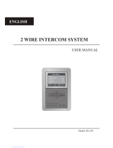
Handset.
B/W or color screen (depending on the model).
Front film.
Function push buttons.
Cord.
Attachment holes.
Identification label.
Connecting points.
CN4 connector.
Three positions call reception volume control.
Cable slot.
Contrast control (color control in case of color screen).
Brightness control.
Monitor
Modelo
CODIGO / CODE
MASTER
18Vdc ± 2V
Standby 15mA
Máximo 450mA
Sistemas de comunicación S.A.
Made in Spain
10ºC + 50ºC
SLAVE
INTER A1 PUERTAESCALERA
ATENCIÓN
Alta tensión. No abrir la tapa.
Manipular sólo por personal
del servicio técnico.
WARNING
High voltage. Don't open cover.
Handle only by technical service.
PISO
Floor DoorStair
PLATEA Plus
0000000000
Nº serie
(*) Second camera activation and call to a slave porter's exchange functions require an internal
modification of the monitor. If any of these functions are required, contact with your nearest
authorized distributor.
Second camera activation disables the intercomm function and call function to a slave
porter's exchange disables optional device function.
MONITOR DESCRIPTION MONITOR DESCRIPTION
escription of the Platea Plus monitor.
Dunction push buttons.
F
escription of the identification label.
D
For an easiest repair, replacement or increasement
of the existing monitors, fill the indentifying label
information.
MASTER: master monitor.
SLAVE: slave monitor.
INTER: slave monitor with intercom function.
A1: monitor connected to an auxiliary device.
CODE: monitor call code (see page 27).
STAIR: building code (see page 11).

25
24
Vin
Vout
Malla
Shield
Malla
Shield
A
HZ-
INT
SA
CTO
2C
A1
VP
MP
D
REF RCPL-PLUS LOTE
CODE 11758882
Colocar la parte superior de la regleta a 1,60m. del suelo.
Place the top part of the monitor connector at 1,60m. from the floor.
50mm.
50mm.
Presionar para abrir.
Press to open.
Terminals +, – and Malla (shield) are duplicated for easiest cascade installation of parallel
monitors or telephones. If the first monitor is not placed on the connector, cascade units
will not be powered.
escription of the RCPL-Plus
Dmonitor connector.
a
a
b
b
f
e
d
c
a. Wall attachment hole (x4).
b. Monitor attachment hook (x2).
c. Vertical wiring input.
d. Attachment clip.
e. Wiring input hole.
f. Installation terminals: positive, ground.
video signal coaxial input.
coaxial shield.
video signal coaxial output.
audio communication.
digital communication.
door bell push button input.
intercom.
auxiliary calling device output.
video distributor activation output.
2nd camera activation output.
optional device activation output.
twisted pair video signal.
+, –:
Vin :
Malla:
Vout :
A :
D :
HZ- :
INT :
SA :
CTO :
2C :
A1 :
Vp, Mp :
L561 module for video installations
Ewith twisted pair cable.
andling the end of line jumper.
H
hanging the front film.
C
The end of line jumper is placed on the CN4 connector, that can be
located on the monitor base.
In case of twisted pair cable installations, the end of line jumper
is placed in the EL561 module, also located in the CN4 connector
of the monitor base.
Do not remove the jumper on monitors where the video cable finish.
Remove the jumper on monitors where the video cable continue.
The monitor is supplied with a reversible front film, that allow the owner
to choose between two colors.
To change the front film, remove the front plate by inserting a plain screwdriver
in the triangle marks, as it is shown on the drawing.
MONITOR ADJUSTMENTS MONITOR CONNECTOR DESCRIPTION
Locate the CN4 connector, that's placed in the monitor base.
Remove the existing jumper and plug the EL561 module.
NOTE: on this type of installations the EL560 module must be
plugged in the CN6 connector of the keypad module (page 8).
Refer to the specific installation diagram.

27
26
Avoid to place the monitor near to heating sources,
in dusty locations or smoky environments.
To install the monitor directly over the wall,
drill two holes of Ø6mm. and use the supplied screws.
The upper part of the monitor connector must be placed
at 1,60m. height roughly. The minimum distance
between the monitor connector and the closest object
must be 5cm.
Place the monitor at right angles to the connector
and align the attaching holes of the monitor
with the attachment hooks of the connector,
as it is shown on the drawing.
Lock out the monitor. Press the right side
till the attachment clip locks the monitor
firmly.
To disassemble the monitor from the connector,
use a plain screwdriver to release the
attachment clip. Remove the monitor from
the connector, with special attention do not
falls.
MONITOR INSTALLATION MONITORS PROGRAMMING
ix the monitor connector to the wall.
F
ix the monitor.
F
golmar 13:15
O.K.
01
rogramming the monitors.
PIn case of a general entrance door panel, program the monitors only from each internal
building door panel, as described on the corresponding instruction manual.
If this door panel is installed on an internal building of a residential complex or on a single
building, program the monitors as follows:
To enter the door panel into program mode, press
key symbol and enter the installer PIN code
(factory default: 1315), as described on page 10.
Switch off the monitor to be programmed.
Once the monitor is off, press the door release push button.
With the door release push button pressed
switch on the monitor.
To show that the system is ready for programming, the panel
will reproduce a sound and the LCD will display the
message program mode, appearing the picture
on the monitor. At this moment, the door release
push button can be released. Lift the handset to stablish
audio communication with the door panel.
Enter the code of the monitor to be
programmed and press the bell key.
At this moment the panel will reproduce
a sound and the monitor led will blink.
To program the monitor as master, switch it
off and on again.
To program it as slave, press the door
release push button.
To program it as slave with intercom
function press the push button.
Each apartment must have one master unit only; in case of parallel units configure them
as slaves, both monitors or telephones.
Repeat these steps to program the rest of monitors.
Once the programming has been finished exit from the programming menu by pressing
CANCEL key. If you don't, the door panel will automatically exit after 90 seconds
with no operation.

29
28
TELEPHONE DESCRIPTION TELEPHONE DESCRIPTION
escription of the T-940 Plus telephone.
D
a.
b.
c.
d.
e.
f.
g.
h.
i.
Telephone handset.
Speaker grille.
Microphone hole.
Subjection hole.
Telephone cord connectors.
Function push buttons.
On-Off light indicator.
Call reception volume control.
Hook switch.
a
d
c
e
i
h
e
b
f
g
The telephone has a three positions switch placed on the bottom
part of the telephone (closest to the telephone cord connector)
that allows to control the call reception level volume.
unction push buttons.
F
On-Off push button.
After any telephone reset, and during the next 45 seconds,
all the telephone functions will be disabled, with the exception
of call reception.
This push button allows to make an intercom call when the handset
is not on the craddle. This function is described on page 43.
If the handset is on the craddle sends a panic call to the porter's
exchanges that have enabled the reception of this type of call.
If not, allows to call to the master porter's exchange.
During call reception and communication progresses allows
the lock release activation.
a.
b.
c.
a
b
c
erminal connector description.
Tpositive, ground.
audio, digital communication.
intercom.
auxiliary calling device output.
door bell push button input.
+ , :
A , D :
INT :
SA :
HZ- :
–
A D
+_SAINT HZ-
TELEPHONE INSTALLATION
ix the telephone.
FIt will be necessary to open the telephone for wiring and
fixing purposes. To open the telephone insert a plain
screwdriver into the slots and rotate it as shown.
Avoid to place the telephone near to
heating sources, in dusty locations or
smoky environments.
The telephone can be fixed using an
electrical embedding box or directly
on the wall, as shown on the picture.
If the telephone will be installed directly
over the wall, drill two holes of Ø6mm.
on the specified positions, using 6mm.
wallplugs and Ø3,5 x 25mm. screws.
Pass the installation wires through the corresponding hole and
connect them as shown on the installation diagrams.
Close the telephone as shown on the picture. Once the telephone
is closed, connect the handset using the telephone cord and
put it on the craddle.

31
30
TELEPHONES PROGRAMMING
Switch off the telephone to be programmed.
Once the telephone is off, press the door release push button.
With the door release push button pressed
switch on the telephone.
To program the telephone as master,
switch it off and on again.
To program it as slave, press the door
release push button.
To program it as slave with intercom
function press the center push button.
MRBO T
R-3
TF-104
SEC
~~ CV+CV- D Malla
Vin-AinAout Vin+ Vout-Vout++CN1
-
INSTALLATION DIAGRAMS
onnexion of an a.c. lock release.
C
As it is described on page 21, the lock releases to be connected to the door panel
must be d.c. type. If an a.c. lock release has been installed before, use a R-3
relay unit and a TF-104 transformer, and connect them to the lock release
as it is shown on the enclosed diagram.
ink of several power supplies units.
LIf the quantity of monitors or telephones to be connected is bigger than the supported
from one power supply (see page 21), use additional power supplies to match the
required quantity. The first power supply should be connected to the door panel and
to the first group of monitors or telephones; connect the next groups to the positive
terminal of its corresponding power supply.
To wire several power supplies link their ground terminals;
NEVER link positive terminals of different power supplies.
To the door panel and to
the first group of monitors
or telephones.
To the second group of
monitors or telephones.
1st FA-Plus 2nd FA-Plus/C or FA-Plus
SEC
PRI
~~
Main
+ +
--
SEC
PRI
~~
Main
+ +
--
Door panel
rogramming the telephones.
P
golmar 13:15
O.K.
01
Each apartment must have one master unit only; in case of parallel units configure them
as slaves, both monitors or telephones.
Repeat these steps to program the rest of telephones.
Once the programming has been finished exit from the programming menu by pressing
CANCEL key. If you don't, the door panel will automatically exit after 90 seconds
with no operation.
In case of a general entrance door panel, program the telephones only from each internal
building door panel, as described on the corresponding instruction manual.
If this door panel is installed on an internal building of a residential complex or on a single
building, program the telephones as follows:
To enter the door panel into program mode, press
key symbol and enter the installer PIN code
(factory default: 1315), as described on page 10.
Enter the code that will be used to call to
this telephone and press the bell key.
At this moment the panel will reproduce
a sound and the telephone led will blink.
To show that the system is ready for programming, the panel
will reproduce a sound and the LCD will display the
message program mode. At this moment, the door
release push button can be released. Lift the handset
to stablish audio communication with the door panel.
1
4
7
2
5
8
3
6 0
9
C

FA-Plus/C
SEC
PRI
~~ + +
--
SEC
PRI
~~ + +
--
32 33
CV+CV- D Malla
Vin-AinAout Vin+ Vout-Vout++
CN1 CN2
-
CV+CV- D Malla
Vin-AinAout Vin+ Vout-Vout++
CN1 CN2
-
JP 4321 JP 4321
A
A
_
_
+
+
D
D
Malla
Malla
Vin
Vin
Vout
Vout
CN4
CN4
A
_
+D
Malla
Vin Vout
CN4
A
_
+D
Malla
Vin Vout
CN4
E
E
D1
D1
D2
D2
+
+
D4L-PLUS
D4L-PLUS
JP1
JP1
S
S
1
4
7
2
5
8
3
6 0
9
C
1
4
7
2
5
8
3
6 0
9
C
FA-Plus/C or FA-Plus
Main Main
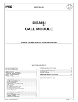
Slave door panelMaster door panel
*Place this power supply
as closest as possible
to the first distributor.
INSTALLATION DIAGRAMS
ideo installation with coaxial cable.
v
The installation diagram shows the connection of a video system with one or several door
panels for the same building.
If the system has one door panel only, override the wiring to the second door panel.
If the system has more than one door panel, wire the second panel as shown on the
diagram. In case of more than two door panels, wire them as the second is connected.
1,00mm² 2,50mm²
0,25mm² 0,25mm²
RG-59 RG-59
Terminal
SECTIONS CHART
50m.
Distance
150m.
A , A , A, D
in out
V , V , V , V
in+ out+ in out
+, –, CV+, CV–
For longer distances than the specified contact with your distributor.
* Take off JP1 jumper
of all the distributors
except in the last one.

SEC
PRI
~~ + +
--
34 35
JP1
FA-Plus/C
SEC
PRI
~~ + +
--
CV+CV- D Malla
Vin-AinAout Vin+ Vout-Vout++
-
CV+CV- D Malla
Vin-AinAout Vin+ Vout-Vout++
-
JP 4321 JP 4321
CN1 CN2CN1 CN2
JP2
A
A
D
D
CT +
+
Vpi
Vd1
Mpi
Md1
_
_
A
D
CT
+
Vd2
Md2
_
AD+Vpo Mpo
_D2L-Plus/2H
VpMp
A D
_
+
EL561
JP1
VpMp
A D
_
+
EL561
JP1
JP2 JP1
A
A
D
D
CT +
+
Vpi
Vd1
Mpi
Md1
_
_
A
D
CT
+
Vd2
Md2
_
AD+Vpo Mpo
_D2L-Plus/2H
VpMp
A D
_
+
EL561
JP1
VpMp
A D
_
+
EL561
JP1
1
4
7
2
5
8
3
6 0
9
C
1
4
7
2
5
8
3
6 0
9
C
INSTALLATION DIAGRAMS
FA-Plus/C or FA-Plus
Main Main
Slave door panelMaster door panel
*Place this power supply
as closest as possible
to the first distributor.
* Take off JP1 jumper
of all the distributors
except in the last one.
IMPORTANT: For this type of installation, the door panels must have plugged an EL560 module
in each and the monitors must have an EL561 plugged in each.
If the CTO terminal is wired, only the distributor connected to the called monitor
will be active. Change the JP2 jumper position of the distributors to enable
this function.
IMPORTANT:
IMPORTANT:
IMPORTANT:
IMPORTANT:
1,00mm² 2,50mm²
0,25mm² 0,25mm²
CAT-5 CAT-5
Terminal
SECTIONS CHART
50m.
Distance
150m.
A , A , A, D
in out
V , V , V , M
in+,- out+,- p,d p,d
+, –, CV+, CV–CTO, CT,
For longer distances than the specified contact with your distributor.
ideo installation without coaxial cable.
v
The installation diagram shows the connection of a video system with one or several door
panels for the same building.
If the system has one door panel only, override the wiring to the second door panel.
If the system has more than one door panel, wire the second panel as shown on the
diagram. In case of more than two door panels, wire them as the second is connected.

SEC
PRI
~~ + +
--
A
A
+
+
_
_
D
D
T-940 Plus
T-940 Plus
A
+_D
T-940 Plus
A
+_D
T-940 Plus
FA-Plus/C
SEC
PRI
~~ + +
--
CV+CV- D Malla
Vin-AinAout Vin+ Vout-Vout++
-
CV+CV- D Malla
Vin-AinAout Vin+ Vout-Vout++
-
JP 4321 JP 4321
CN1 CN2CN1 CN2
1
4
7
2
5
8
3
6 0
9
C
1
4
7
2
5
8
3
6 0
9
C
36 37 INSTALLATION DIAGRAMS
FA-Plus/C or FA-Plus
Main Main
Slave door panelMaster door panel
udio installation.
A
1,00mm² 2,50mm²
0,25mm² 0,25mm²
Terminal
SECTIONS CHART
50m.
Distance
150m.
A , A , A, D
in out
+, –, CV+, CV–
*Place this power supply
as closest as possible
to the first telephone.
The installation diagram shows the connection of an audio system with one or several door
panels for the same building.
If the system has one door panel only, override the wiring to the second door panel.
If the system has more than one door panel, wire the second panel as shown on the
diagram. In case of more than two door panels, wire them as the second is connected.
For longer distances than the specified contact with your distributor.
/