Page is loading ...

Truck Mounted Equipment
Operation & Maintenance Manual
Compressor Module
VHP600CM
Doosan Infracore Portable Power
1293 Glenway Drive
Statesville, NC 28625
www.doosanportablepower.com
Book: 23362551 (9/08) Rev A
This manual contains important safety information.
Do not destroy this manual.
This manual must be available to the personnel who operate and maintain this machine.
Revised (10-12)
Doosan purchased Bobcat Company from Ingersoll-Rand Company in
2007. Any reference to Ingersoll-Rand Company or use of trademarks,
service marks, logos, or other proprietary identifying marks belonging
to Ingersoll-Rand Company in this manual is historical or nominative
in nature, and is not meant to suggest a current affiliation between
Ingersoll-Rand C
ompany and Doosan
Company or the products of
e
ith
er.

2

3
TABLE OF CONTENTS
Operation & Maintenance Manual
TITLE PAGE
SAFETY . . . . . . . . . . . . . . . . . . . . . . . . . . . . . . . . . . . . . . . . . . . . . . . . . . . . . . . . . . . . . . 5
Safety Precautions . . . . . . . . . . . . . . . . . . . . . . . . . . . . . . . . . . . . . . . . . . . . . . . . . . . . . . . . . . . . . . 6
General Information . . . . . . . . . . . . . . . . . . . . . . . . . . . . . . . . . . . . . . . . . . . . . . . . . . . . . . . . . . 6
Safety Labels . . . . . . . . . . . . . . . . . . . . . . . . . . . . . . . . . . . . . . . . . . . . . . . . . . . . . . . . . . . . . . . . . . 9
INSTALLATION . . . . . . . . . . . . . . . . . . . . . . . . . . . . . . . . . . . . . . . . . . . . . . . . . . . . . . . . 17
System Description - General. . . . . . . . . . . . . . . . . . . . . . . . . . . . . . . . . . . . . . . . . . . . . . . . . . . . . . 18
Mounting Unit . . . . . . . . . . . . . . . . . . . . . . . . . . . . . . . . . . . . . . . . . . . . . . . . . . . . . . . . . . . . . . . . . . 19
Inlet Piping . . . . . . . . . . . . . . . . . . . . . . . . . . . . . . . . . . . . . . . . . . . . . . . . . . . . . . . . . . . . . . . . . . . . 19
Piping - General . . . . . . . . . . . . . . . . . . . . . . . . . . . . . . . . . . . . . . . . . . . . . . . . . . . . . . . . . . . . . . . . 20
Compressor Discharge Piping . . . . . . . . . . . . . . . . . . . . . . . . . . . . . . . . . . . . . . . . . . . . . . . . . . . . . 20
Receiver Separator Discharge Piping. . . . . . . . . . . . . . . . . . . . . . . . . . . . . . . . . . . . . . . . . . . . . . . . 21
Wiring . . . . . . . . . . . . . . . . . . . . . . . . . . . . . . . . . . . . . . . . . . . . . . . . . . . . . . . . . . . . . . . . . . . . . . . . 21
Driver. . . . . . . . . . . . . . . . . . . . . . . . . . . . . . . . . . . . . . . . . . . . . . . . . . . . . . . . . . . . . . . . . . . . . . . . . 21
Regulation. . . . . . . . . . . . . . . . . . . . . . . . . . . . . . . . . . . . . . . . . . . . . . . . . . . . . . . . . . . . . . . . . . . . . 22
GENERAL DATA . . . . . . . . . . . . . . . . . . . . . . . . . . . . . . . . . . . . . . . . . . . . . . . . . . . . . . . 23
Unit Model - VHP600CM. . . . . . . . . . . . . . . . . . . . . . . . . . . . . . . . . . . . . . . . . . . . . . . . . . . . . . . . . . 24
OPERATING INSTRUCTIONS. . . . . . . . . . . . . . . . . . . . . . . . . . . . . . . . . . . . . . . . . . . . . 25
Set-Up. . . . . . . . . . . . . . . . . . . . . . . . . . . . . . . . . . . . . . . . . . . . . . . . . . . . . . . . . . . . . . . . . . . . . . . . 26
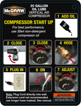
Procedure For Airend Oil Priming . . . . . . . . . . . . . . . . . . . . . . . . . . . . . . . . . . . . . . . . . . . . . . . . . . 26
Before Starting . . . . . . . . . . . . . . . . . . . . . . . . . . . . . . . . . . . . . . . . . . . . . . . . . . . . . . . . . . . . . . . . . 27
Starting/Operating. . . . . . . . . . . . . . . . . . . . . . . . . . . . . . . . . . . . . . . . . . . . . . . . . . . . . . . . . . . . . . . 28
Stopping . . . . . . . . . . . . . . . . . . . . . . . . . . . . . . . . . . . . . . . . . . . . . . . . . . . . . . . . . . . . . . . . . . . . . . 29
Equipment Protection . . . . . . . . . . . . . . . . . . . . . . . . . . . . . . . . . . . . . . . . . . . . . . . . . . . . . . . . . . . . 29
High Discharge Air Temperature. . . . . . . . . . . . . . . . . . . . . . . . . . . . . . . . . . . . . . . . . . . . . . . . . . . . 29
Operating Instruments. . . . . . . . . . . . . . . . . . . . . . . . . . . . . . . . . . . . . . . . . . . . . . . . . . . . . . . . . . . . 30
On Panel. . . . . . . . . . . . . . . . . . . . . . . . . . . . . . . . . . . . . . . . . . . . . . . . . . . . . . . . . . . . . . . . . . . 30
Inside . . . . . . . . . . . . . . . . . . . . . . . . . . . . . . . . . . . . . . . . . . . . . . . . . . . . . . . . . . . . . . . . . . . . . 30
Pressure Regulator Adjusting Instructions . . . . . . . . . . . . . . . . . . . . . . . . . . . . . . . . . . . . . . . . . . . .31
Before Starting . . . . . . . . . . . . . . . . . . . . . . . . . . . . . . . . . . . . . . . . . . . . . . . . . . . . . . . . . . . . . . 31
After Starting Unit . . . . . . . . . . . . . . . . . . . . . . . . . . . . . . . . . . . . . . . . . . . . . . . . . . . . . . . . . . . . 31

4
TABLE OF CONTENTS
Operation & Maintenance Manual
TITLE PAGE
MAINTENANCE . . . . . . . . . . . . . . . . . . . . . . . . . . . . . . . . . . . . . . . . . . . . . . . . . . . . . . . . 33
General . . . . . . . . . . . . . . . . . . . . . . . . . . . . . . . . . . . . . . . . . . . . . . . . . . . . . . . . . . . . . . . . . . . . . . . 34
Scheduled Maintenance . . . . . . . . . . . . . . . . . . . . . . . . . . . . . . . . . . . . . . . . . . . . . . . . . . . . . . . . . . 34
Compressor Oil Level . . . . . . . . . . . . . . . . . . . . . . . . . . . . . . . . . . . . . . . . . . . . . . . . . . . . . . . . . . . . 35
Aircleaner . . . . . . . . . . . . . . . . . . . . . . . . . . . . . . . . . . . . . . . . . . . . . . . . . . . . . . . . . . . . . . . . . . . . . 35
Gauges . . . . . . . . . . . . . . . . . . . . . . . . . . . . . . . . . . . . . . . . . . . . . . . . . . . . . . . . . . . . . . . . . . . . . . . 36
Compressor Oil and Hydraulic Oil Combination Cooler . . . . . . . . . . . . . . . . . . . . . . . . . . . . . . . . . . 36
Hoses . . . . . . . . . . . . . . . . . . . . . . . . . . . . . . . . . . . . . . . . . . . . . . . . . . . . . . . . . . . . . . . . . . . . . . . . 37
Compressor Oil Filter . . . . . . . . . . . . . . . . . . . . . . . . . . . . . . . . . . . . . . . . . . . . . . . . . . . . . . . . . . . . 37
Fasteners . . . . . . . . . . . . . . . . . . . . . . . . . . . . . . . . . . . . . . . . . . . . . . . . . . . . . . . . . . . . . . . . . . . . . 39
Receiver-Separator Systems . . . . . . . . . . . . . . . . . . . . . . . . . . . . . . . . . . . . . . . . . . . . . . . . . . . . . . 39
Scavenge Line . . . . . . . . . . . . . . . . . . . . . . . . . . . . . . . . . . . . . . . . . . . . . . . . . . . . . . . . . . . . . . . . . 40
Oil Separator Element. . . . . . . . . . . . . . . . . . . . . . . . . . . . . . . . . . . . . . . . . . . . . . . . . . . . . . . . . . . . 40
Exterior Finish Care . . . . . . . . . . . . . . . . . . . . . . . . . . . . . . . . . . . . . . . . . . . . . . . . . . . . . . . . . . . . . 41
Drive Belt. . . . . . . . . . . . . . . . . . . . . . . . . . . . . . . . . . . . . . . . . . . . . . . . . . . . . . . . . . . . . . . . . . . . . . 42
Field Repair Texture Paint . . . . . . . . . . . . . . . . . . . . . . . . . . . . . . . . . . . . . . . . . . . . . . . . . . . . . . . . 42
Maintenance Schedule . . . . . . . . . . . . . . . . . . . . . . . . . . . . . . . . . . . . . . . . . . . . . . . . . . . . . . . . . . . 44
LUBRICATION . . . . . . . . . . . . . . . . . . . . . . . . . . . . . . . . . . . . . . . . . . . . . . . . . . . . . . . . . 45
General Information . . . . . . . . . . . . . . . . . . . . . . . . . . . . . . . . . . . . . . . . . . . . . . . . . . . . . . . . . . . . . 46
Compressor Oil Change . . . . . . . . . . . . . . . . . . . . . . . . . . . . . . . . . . . . . . . . . . . . . . . . . . . . . . . . . . 47
Portable Compressor Fluid Chart . . . . . . . . . . . . . . . . . . . . . . . . . . . . . . . . . . . . . . . . . . . . . . . . . . . 48
TROUBLE SHOOTING. . . . . . . . . . . . . . . . . . . . . . . . . . . . . . . . . . . . . . . . . . . . . . . . . . . 51
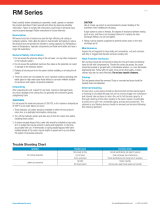
Introduction . . . . . . . . . . . . . . . . . . . . . . . . . . . . . . . . . . . . . . . . . . . . . . . . . . . . . . . . . . . . . . . . . . . . 52
Action Plan . . . . . . . . . . . . . . . . . . . . . . . . . . . . . . . . . . . . . . . . . . . . . . . . . . . . . . . . . . . . . . . . . . . . 52
Think Before Acting . . . . . . . . . . . . . . . . . . . . . . . . . . . . . . . . . . . . . . . . . . . . . . . . . . . . . . . . . . 52
Do the Simplest Things First . . . . . . . . . . . . . . . . . . . . . . . . . . . . . . . . . . . . . . . . . . . . . . . . . . . 52
Double Check Before Disassembly . . . . . . . . . . . . . . . . . . . . . . . . . . . . . . . . . . . . . . . . . . . . . . 53
Find and Correct Basic Cause . . . . . . . . . . . . . . . . . . . . . . . . . . . . . . . . . . . . . . . . . . . . . . . . . .53
Trouble Shooting Chart . . . . . . . . . . . . . . . . . . . . . . . . . . . . . . . . . . . . . . . . . . . . . . . . . . . . . . . . . . 54

Book: 23362551 (9-08) 5
Safety

Operation & Maintenance Manual Safety
6 Book: 23362551 (9-08)
Safety
Safety Precautions
General Information
Ensure that the operator reads and understands the decals and consults the manuals before
maintenance operation.
Ensure that the Operation and Maintenance manual, and the manual holder if equipped, are
not removed permanently from the machine.
Ensure that maintenance personnel are adequately trained, competent and have read the
manuals.
Make sure that all protective covers are in place and that the canopy/doors are closed during
operation.
The specification of this machine is such that the machine is not suitable for use in flammable
gas risk areas. If such an application is required, then all local regulations, codes of practice
and site rules must be observed. To ensure that the machine can operate in a safe and reliable
manner, additional equipment such as gas detection, exhaust spark arrestors, and intake
(shutoff) valves may be required, dependent on local regulations or the degree of risk involved.
Air discharged from this machine may contain carbon monoxide or other contaminants, which
will cause serious injury or death. Do not breathe this air.
Compressed air can be dangerous if incorrectly handled. Before doing any work on the unit,
ensure that all pressure is vented from the system and that the machine cannot be started
accidentally.
Ensure that the machine is operating at the rated pressure and that all relevant personnel
know the rated pressure.
All air pressure equipment installed in or connected to the machine must have safe working
pressure ratings of at least the machine safety valve rating.
If more than one compressor is connected to one common downstream plant, effective check
valves and isolation valves must be fitted and controlled by work procedures, so that one
machine cannot accidentally be pressurized or over pressurized by another.
Compressed air must not be used for a feed to any form of breathing apparatus or mask.
The discharged air contains a very small percentage of compressor lubricating oil and care
should be taken to ensure that downstream equipment is compatible.
If the discharged air is to be ultimately released into a confined space, adequate ventilation
must be provided.
When using compressed air, always use appropriate personal protective equipment.
All pressure containing parts, especially flexible hoses and their couplings, must be regularly
inspected, be free from defects and be replaced according to the Manual instructions.
Avoid bodily contact with compressed air.

Safety Operation & Maintenance Manual
Book: 23362551 (9-08) 7
The safety valve located in the separator tank must be checked periodically for correct
operation.
Never operate unit without first observing all safety warnings and carefully reading the
operation and maintenance manual shipped from the factory with this machine.
Never operate the engine of this machine inside a building without adequate ventilation. Avoid
breathing exhaust fumes when working on or near the machine. Do not alter or modify this
machine.
A battery contains sulfuric acid and can give off gases, which are corrosive and potentially
explosive. Avoid contact with skin, eyes and clothing. In case of contact, flush area
immediately with water.
Exercise extreme caution when using booster battery. To jump battery, connect ends of one
booster cable to the positive (+) terminal of each battery. Connect one end of other cable to
the negative (-) terminal of the booster battery and other end to a ground connection away
from dead battery (to avoid a spark occurring near any explosive gases that may be present).
After starting unit, always disconnect cables in reverse order.
Never operate unit without first observing all safety warnings and carefully reading the
operation and maintenance manual shipped from the factory with this machine.
This machine may include such materials as oil, diesel fuel, antifreeze, brake fluid, oil/air filters
and batteries which may require proper disposal when performing maintenance and service
tasks. Contact local authorities for proper disposal of these materials.
Air discharged from this machine may contain carbon monoxide or other contaminants, which
will cause serious injury or death. Do not breathe this air.
High Pressure Air can cause serious injury or death. Relieve pressure before removing filler
plugs/caps, fittings or covers.
Air pressure can remain trapped in air supply line, which can result in serious injury or death.
Always carefully vent air supply line at tool or vent valve before performing any service.
This machine produces loud noise with the doors open or service valve vented. Extended
exposure to loud noise can cause hearing loss. Always wear hearing protection when doors
are open or service valve is vented.
Never inspect or service unit without first disconnecting battery cable(s) to prevent accidental
starting.
Do not remove the pressure cap from a HOT radiator. Allow radiator to cool down before
removing pressure cap.
Do not use petroleum products (solvents or fuels) under high pressure as this can penetrate
the skin and result in serious illness. Wear eye protection while cleaning unit with compressed
air to prevent debris from injuring eye(s).
Disconnect air hoses whip and can cause serious injury or death. Always attach a safety flow
restrictor to each hose at the source of supply or branch line in accordance with OSHA
Regulation 29CFR Section 1926.302 (b).
Hot pressurized fluid can cause serious burns. Do not open radiator while hot.
Rotating fan blade can cause serious injury. Do not operate without guard in place.

Operation & Maintenance Manual Safety
8 Book: 23362551 (9-08)
Use care to avoid contacting hot surfaces (engine exhaust manifold and piping, air receiver
and air discharge piping, etc.).
Ether is an extremely volatile, highly flammable gas. USE SPARINGLY! If too much is injected,
it may result in costly damage to the engine.
Never allow the unit to sit stopped with pressure in the receiver – separator system. As a
precaution, open the manual blowdown valve.
Never operate unit with guards, covers or screens removed. Keep hands, hair, clothing, tools,
etc. well away from moving parts.
Make sure wheels, tires and tow bar connectors are in safe operating condition and tow bar is
properly connected before towing.
Whenever the machine is stopped, air will flow back into the compressor system from devices
or systems downstream of the machine unless the service valve is closed. Install a check valve
at the machine service valve to prevent reverse flow in the event of an unexpected shutdown
when the service valve is open.
Hazardous Substance Precaution
The following substances are used in the manufacture of this machine and may be hazardous
to health if used incorrectly.
Precaution: Avoid ingestion, skin contact and breathing fumes for the following substances:
Antifreeze, Compressor Oil, Engine Lubricating Oil, Preservative Grease, Rust Preventative,
Diesel Fuel and Battery Electrolyte.
The following substances may be produced during the operation of this machine and may be
hazardous to health:
• Avoid build-up of Engine Exhaust Fumes in confined spaces.
• Avoid breathing Exhaust Fumes.
• Avoid breathing Brake Lining Dust during maintenance.

Safety Operation & Maintenance Manual
Book: 23362551 (9-08) 9
Safety Labels
Look for these signs on machines shipped to international markets outside North
America, which point out potential hazards to the safety of you and others. Read and
understand thoroughly. Heed warnings and instructions. If you do not understand,
inform your supervisor.
Corrosion risk
Hot surface
Lifting point.
No open flame
Lifting point.
WARNING: Electrical shock risk
Diesel Fuel.
No open flame
Do not operate the machine
without guard being fitted.
WARNING - Flammable liquid
When parking use prop stand,
handbrake and wheel chocks
Air/gas flow or Air discharge.
WARNING - Hot and harmful
exhaust gas.
Tie down point
Do not breathe the compressed
air from this machine
Parking Brake
P
DIESEL

Operation & Maintenance Manual Safety
10 Book: 23362551 (9-08)
Read the Operation and Maintenance
manual before operation or maintenance
of this machine is undertaken.
WARNING - Consult the operation
and maintenance manual before
commencing any maintenance.
Do not stack.
Do not use fork lift truck from this side.
WARNING - Before connecting the tow bar
or preparing to tow, consult the
operation and maintenance manual.
On (power).
Off (power).
X,X
BAR
WARNING - Maintain correct tire pressure
(Refer to the GENERAL INFORMATION
section of this manual.
Do not operate with the doors
or enclosure open
Emergency stop.
1.5m.
IP54
Rough Service Designation
Wet Location Operation
Replace any cracked
protective shield.

Safety Operation & Maintenance Manual
Book: 23362551 (9-08) 11
0° C
Pressurized component
or system.
Use fork lift truck from
this side only
Pressurized vessel.
WARNING - For operating temperature below
0° C, consult the operation and maintenance
manual
Do not remove operating and maintenance
manual and manual holder from this machine.
Read the Operation and Maintenancemanual
before operation or maintenance of this
machine is undertaken.
WARNING - Do not undertake any
maintenance on this machine until the
electrical supply is disconnected and the air
pressureis totally relieved.
Do not exceed the speed limit.
Oil Drain

Operation & Maintenance Manual Safety
12 Book: 23362551 (9-08)
Look for these signs on machines shipped to international markets outside North
America, which point out potential hazards to the safety of you and others. Read and
understand thoroughly. Heed warnings and instructions. If you do not understand,
DANGER
!
WARNING
!
CAUTION
!
NOTICE
Indicates the presence of a hazard which WILL
cause serious injury, death or property damage, if
ignored.
Indicates the presence of a hazard which CAN
cause serious injury, death or property damage, if
ignored.
Indicates the presence of a hazard which WILL or
can cause injury or property damage, if ignored.
Indicates important set-up, operating or
maintenance information.
(Red Background)
(Orange Background)
(Yellow Background)
(Blue Background)
inform your supervisor.

Safety Operation & Maintenance Manual
Book: 23362551 (9-08) 13
WARNING
Hot pressurized fluid.
Can cause severe
burns.
Do not open radiator
while hot.
WARNING
High pressure air.
Can cause serious
injury or death.
Relieve pressure before
removing filler plugs/caps,
fittings or coverrs.
WARNING
Trapped air pressure.
Can cause serious
injury or death
Close service valve and
operate tool to vent
trapped air before
performing any service
DANGER
Discahrged air can contain carbon
monoxide or other contaminants.
Will cause serious injury or death.
Do not breathe this air.

Operation & Maintenance Manual Safety
14 Book: 23362551 (9-08)
WARNING
Modification or alternation of this machine.
Can cause serious injury or death.
Do not alter modify this machine
without the express written consent of
the manufacturer.
Improper operation of this equipment.
Can cause serious injury or death.
Read Operator's Manual supplied with
this machine before operation or
servicing.
WARNING
Rotating fan blade.
Can cause serious injury.
Do not operate without
guard on place.
Disconnected air hoses whip.
Can cause serious
injury or death.
When using air tools
attach safety device
(OSHA valve) at source of
air supply for each tool.
WARNING
WARNING
Combustible gas.
Can cause serious burns,
blindness or death.
Keep sparks and open
flames away from batteries.
Falling of machine.
Can cause serious injury
or death.
Access lifting bail from
inside machine.
WARNING
WARNING
Door under pressure.
Can cause serious injury.
Use both hands to open door
when machine is running.
CAUTION
DO NOT WELD.
ELECTRONIC DAMAGE
WILL OCCUR.
This engine is equipped with an
electronic engine controller and
other electronic components.
WARNING
Excessive towing speed.
Can cause serious injury
or death.
Do NOT exceed 65 mph (105 km/hr.)
Collapsing jackstand.
Can cause serious injury.
Insert locking pin completely.
105
km/h

Safety Operation & Maintenance Manual
Book: 23362551 (9-08) 15
CAUTION
This engine is equipped with an
electric heater starting aid.
DO NOT USE ETHER.
ENGINE DAMAGE WILL OCCUR.
COOLANT FILL INSTRUCTIONS
Adding:
Replacing:
With system cool, remove radiator cap. Drain
coolant and close drain. At radiator, refill system.
Replace radiator cap. At reservoir, fill to "HOT" level.
Run for 30 minutes. Stop and allow to cool.
At reservoir, add coolant as necesary to reach
"COLD" level.
Do NOT remove radiator cap. Top offat overflow
reservoir. Use same anti-freeze mixture as in
radiator.
NOTICE
USE DIESEL
FUEL ONLY
FREE SAFETY DECALS!
To promote communication of Safety Warnings on
products manufactured by the Portable Compressor
Division in Mocksville. N.C., Safety Decals are available
free of charge. Safety decals are identified by the decal
heading: DANGER, WARNING or CAUTION.
Decal part numbers are on the bottom of each decal and
are also listed in the compressor's parts manual. Submit
order for Safety Decals to the Mocksville Parts Service
Department. The no charge order should contain only
Safety Decals. Help promote product safety! Assure that
decals are present on the machines. Replace decals that
are not readable.
FREE SAFETY DECALS
Do not paint over safety warnings or instructional decals. If safety warning decals
become illegible, immediately order replacements from the factory.
Safety Decals are available free of charge. Safety Decals are identified by the
decal heading: DANGER, WARNING, or CAUTION.
Decal part numbers are on the bottom of each decal and are also listed in the
compressor’s parts manual. Submit orders for Safety Decals to the Portable
Power Parts Service Department. The no charge order should contain only
Safety Decals. Help promote safety! Assure that decals are present on the
machines. Replace decals that are not readable.

16 Book: 23362551 (9-08)

Book: 23362551 (9-08) 17
Installation

Operation & Maintenance Manual Installation
18 Book: 23362551 (9-08)
Installation
System Description - General
The compressor modules are semi-packaged, air-cooled units designed for power take-off
applications. Each unit is designed to operate at ambient temperatures from -10° F to 125° F
(-23.3° C to 51.7° C). For the actual delivery of each unit at its rated operating pressure, refer
to the General Data Decal supplied with each unit.
The unit includes an oil-flooded, rotary, screw-type air compressor, a compressor inlet system,
a capacity control system, a compressor lubricating oil system, a compressor discharge
system as well as basic instrumentation. The compressor inlet system includes an air intake
cleaner with a service indicator. The capacity control system includes a pressure regulator
linked to compressor inlet unloader valve. The compressor lubricating oil system includes an
air-cooled type oil cooler, an oil filter, and oil control valve and an oil separator tank and air
receiver. The oil cooler is of the fin and tube-type construction that requires forced draft cooling
air. Basic instrumentation includes compressor discharge air pressure, hour meter, and air
restriction indicator. The enclosure cabinet, in which the components are mounted, is of heavy
gauge sheet steel and is equipped with easy opening access panels for performing routine
maintenance functions.
Compression in the screw-type air compressor is created by the meshing of two helical rotors
(male and female) on parallel shafts enclosed in a heavy-duty cast iron housing with air inlet
and outlet ports located at opposite ends. The male rotor has four lobes, 90 degrees apart and
the female rotor has six grooves 60 degrees apart. The grooves of the female rotor mesh with
and are driven by the male rotor.
Thrust taper roller bearings at the rear of the airend prevent longitudinal movement of the
rotors. As rotation of the compressor occurs, the rotors unmesh and free air is drawn into the
cavities or pockets between the male rotor lobes and the grooves of the female rotor. The air
is trapped in these pockets and follows the direction of rotation of each rotor. As soon as the
inlet port is closed, the compression cycle begins and the trapped air is directed to the opposite
or discharge side of the rotor housing.
As the rotors mesh, the normal free volume of air is decreased and the pressure increased
until the closing pocket reaches the discharge port. Cooled lubricating oil is admitted to the
compressor by being injected, in metered amounts, directly into the rotor housing so that it
passes on with the air being compressed. This removes the heat of compression to a large
degree and results in a relatively low, final discharge air temperature.
Since the Doosan Portable Power Compressor Module Series unit is of the positive
displacement type, an airflow control system must be provided to regulate the volume of air
passing through the compressor to match the amount of service air required by the customer.
Constant speed control unloads the compressor at a predetermined pressure while the driving
unit continues to operate at full speed. An air operated regulator closing off the intake to the
compressor in an infinitely variable or stepless manner through the inlet unloader valve
accomplishes this.
The discharge air pressure can be controlled between 77and 200 psig (531 to 1379 kPa) by
simple readjustment of the pressure regulator adjusting screw. Unit is shipped set at 125 psig
(1005 kPa).

Installation Operation & Maintenance Manual
Book: 23362551 (9-08) 19
Mounting Unit
Satisfactory installation depends upon the ability of the installer. Refer to the appropriate
foundation plan for the dimensions of the compressor package and the appropriate separator
foundation plan for the dimensions of the combination primary oil separator tank-air receiver
and the secondary separator tank (hereafter called the receiver separator).
Choose a clean, relatively cool location for the compressor package, and provide ample space
around the unit for general accessibility and to ensure effective heat dissipation. Extreme care
must be taken in locating an air-cooled unit of this type so there is an unrestricted supply of air
to the cooling fan, which pushes air over the oil cooler core. The cooler discharge air must flow
away from the unit so that it may be readily dissipated to atmosphere without recirculating hot
air to the fan intake.
Any recirculation of the cooling air may result in an excessively high compressor operating
temperature. The compressor package must be located so the instrument panel will be fully
visible (discharge pressure gauge, discharge temperature gauge, and air cleaner service
indicator).
For the installation of the receiver separator, choose a location that is on the same level as or
lower than the compressor package. Ample space must be provided around the receiver to
ensure the proper installation of all piping connections. In addition, the receiver separator must
be located so that the separator element may be removed for inspection and service. Refer to
the appropriate separator foundation plan.
A condensate drain valve is factory supplied with the receiver separator. When installing the
receiver separator, provision should be made for easy access to this drain valve as it will be
necessary to drain the condensate daily before starting the unit.
Note: The condensate drain valve and line must be located as the lowest point in the
lubricating and cooling oil system for effective condensate removal.
Exact level is not absolutely necessary, but it is recommended the unit be leveled with a sight
glass or a carpenter’s level set on the compressor housing. Leveling may be accomplished by
shimming the unit near the unit’s bolting holes. Be sure to use steel shims. Mounting holes are
provided on the bottom of the base and weld nuts are provided on the sides of the frame. Either
may be used for mounting.
Compressor noise levels will not benefit from using isolators on low shock and vibration
applications such as a truck, due to the inherent low vibration signature of this compressor.
Inlet Piping
Each unit is supplied with a single standard air cleaner to protect the compressor from normal
airborne dust and dirt.

Operation & Maintenance Manual Installation
20 Book: 23362551 (9-08)
Piping - General
Doosan Portable Power Compressor Module units will require customer provided piping from
the compressor module to the hydraulic supply and the air service piping. These hoses are not
provided with the units, as the required lengths of the hoses are dependent on the relative
locations of modules in its installed location. It is left to the installer to obtain hoses of the
correct type and length for each installation.
All hoses terminate at marked bulkhead fittings on drive end of machine, except oil cooler
connections, which are on the cooler side of the compressor module.
All hoses terminate in Type 1 SAE J516 (female swivel straight), 37°JIC flare fittings.
Ports “B” and “C” on oil temperature bypass valve can be connected to either port on the oil
cooler. Oil cooler performance is not sensitive to flow direction.
Compressor Discharge Piping
The customer must furnish the connection between the compressor package and the receiver
separator. It is recommended the customer use a flexible line of 2 inches or larger. All piping
must be certified safe for the pressures and temperatures involved.
Location Fitting Size Hose Size Hose Type
Compressor Module to Oil Temp
Bypass Valve Outlet (Filter)
20 JIC
Compressor Module to Separator
Scavenge
-4 JIC 3/4" (-12) Parker-Hannifin 213 or equivalent
Compressor Module to Air Pressure
Regulator Outlet
-6 JIC 1" (-16) Parker-Hannifin 213 or equivalent
Compressor Module to Separator
Discharge
8 JIC 3/4" (-12) Parker-Hannifin 213, or Aeroquip
FC350, or equivalent
Compressor Module to Oil Cooler
Drain
-6 JIC 1/4" - 4 Parker-Hannifin 213, or Aeroquip
FC350, or equivalent
Oil Cooler to Oil Temp Bypass Valve
Port “B”
20 JIC Parker-Hannifin 206, or Aeroquip
FC300, or equivalent
Oil Cooler to Oil Temp Bypass Valve
Port “C”
20 JIC Parker-Hannifin 206, or Aeroquip
FC300, or equivalent
Airend Discharge to Receiver/
Separator Inlet
-32 JIC Parker-Hannifin 206, or Aeroquip
FC300, or equivalent
/