GROHE Avensys Installation Instructions And Operating Manual
- Category
- Sanitary ware
- Type
- Installation Instructions And Operating Manual

Installation Instructions and Operating Guide
Please leave this document with the user after finishing installation!
95.575.131/ÄM 30 222/09.00
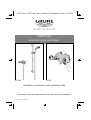
Avensys
Exposed Single Lever Mixer
33 389 33 396
955751.book : t95575.fm Seite 1 Mittwoch, September 20, 2000 10:10 AM

I
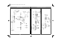
Mixer Body
Wallplugs
Shower Rail
Handshower
Flexible Hose
Filter
Outlet
Screws
Backplate
Escutcheons
Threaded Ring
Flow Limiter
Plug
Nipple
Filter
Table Of Contents
Installation Dimensions (mm)
1 2
33 389 33 396
kl955751.fm Seite 1 Montag, August 21, 2000 3:11 PM

II
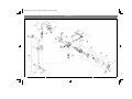
Spare Parts
3 4
kl955751.fm Seite 2 Montag, August 21, 2000 3:11 PM

5
Index
Spare Parts
Table Of Contents . . . . . . . . . . . . . . . . . 1
Installation Dimensions . . . . . . . . . . . . 2
Spare Parts Drawing. . . . . . . . . . . . 3 + 4
Spare Parts List. . . . . . . . . . . . . . . . . . . 5
Technical Data. . . . . . . . . . . . . . . . . . . . 6
Installation. . . . . . . . . . . . . . . . . . . . . . . 7
Exposed Installation. . . . . . . . . . . . . . . 7
Pipe And Shower Hose Connection. . . 9
Maximum Hot Water Limit Setting . . . 10
Maintenance . . . . . . . . . . . . . . . . . . . . 11
Care . . . . . . . . . . . . . . . . . . . . . . . . . . . 12
Trouble Shooting . . . . . . . . . . . . . . . . 12
Guarantee . . . . . . . . . . . . . . . . . . . . . . 15
Dear Customer,
Thank you for choosing a GROHE product.
Please follow these instructions carefully
and you will enjoy many years of reliable
service from this fitting.
No. Description Cat.-No.
Pack-
ing
unit
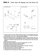
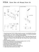
7 Hand shower 28 216 1
7.1 Adjustment ring 45 794 1
7.2 Filter 07 002 2
8 Shower rail 28 666 1
8.1 Sliding shower holder 07 659 1
8.2 Shower rail holder 45 362 1
8.2.1 Cover cap 45 363 1
9 Flexible hose 28 161 1
Optional accessory
10 Compensation ring 45 406 1
No. Description Cat.-No.
Pack-
ing
unit
1 Lever 46 349 1
1.1 Fixing set 46 372 1
2 Cap 46 363 1
3 Temperature limiter 46 308 1
4 Ceramic cartridge 46 386 1
4.1 Seal kit 46 387 1
5 Set screw 02 125 5
6 Connection elbow 12 109 2
6.1 Flow limiter set 46 428 1
6.2 O-ring seal 01 287 10
6.3 Filter 06 768 5
6.4 Escutcheon 00 197 2
955751.book : i95575gb.fm Seite 5 Mittwoch, September 20, 2000 10:10 AM

6
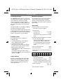
Technical Data
Functioning Principle
This Avensys mixing valve is a single lever
mixer with ceramic cartridge. Lifting the lever
opens water flow. Turning to the left in-
creases temperature and to the right de-
creases temperature. Shutting off the single
lever mixer is possible in any temperature
position.
Hot water limitation is possible by installing
the attached temperature limiter.
This product is supplied with connectors to fit
ø 15mm pipework. Connection should be hot
left, cold right as viewed from the operating
position. The product is preassembled.
Plumbing Systems
This single lever mixer is suitable for
installation with:
• Gravity-fed plumbing systems with an
open vented hot water cylinder
• Cold water storage cistern
• Mains pressure unvented and instantan-
eous thermal hot water storage systems
• Multi-point gas water heaters
• Combination boilers with a modulating hot
water output
To maintain sufficient hot water output
ensure the combination boiler temperature
setting is on high.
Supply Pipework
Ensure the supply pipework is thoroughly
flushed before installing the mixing valve.
GROHE recommends installing isolating
valves upstream of the mixing valve for
servicing purposes.
New Water Regulations
This GROHE-product should be installed to
comply with the New Water Regulations
covering backflow prevention. It must also
be installed in accordance with local bye-law
requirements.
Specification
• Exposed single lever shower mixer,
concealed or exposed supplies
• Flow pressure
- Low pressure 0.1 - 1 bar
- High pressure 1 - 5 bar
Greater than 5 bar, fit pressure reducing
valve
• Avoid major pressure differences between
hot and cold water supply
- If the pressure difference between hot
and cold water supply is higher than
1 bar install attached green flow limiter
(7 l/min) in the cold water connection
elbow
• Max. operating pressure 10 bar
• Max. test pressure 16 bar
• Mixed water flow rate without downstream
resistance:
• Temperature
- Max. (hot water inlet) 80 °C
- Recommended (for economy) 60 °C
- Max. outlet temperature can be pre-set
using the adjustable temperature limiter.
• Water connection hot - LH
cold - RH
• Non reversible cartridge
Pressure 0.1 0.2 0.3 0.4 0.5 0.6 bar
Flow rate 10.2 14.4 17.7 20.4 22.8 25 l/min
955751.book : i95575gb.fm Seite 6 Mittwoch, September 20, 2000 10:10 AM

7
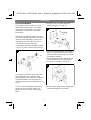
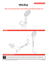
Installation
Exposed Installation
The single lever shower mixer can be in-
stalled in two different ways. The mixing
outlet can be at the bottom for use with a
handshower or at the top for use with a
headshower.
If the pressure difference between hot and
cold water supply is higher than 1 bar install
attached green flow limiter (7 l/min) in the
cold water connection elbow, see Fig. [1].
• Screw out connection elbow (A).
• Install green flow limiter (B) with threaded
ring (C) by using a 12mm socket spanner.
The Single Lever Mixer is fixed to the wall
via the backplate and connected to the
supply pipes by a pair of elbows. The elbows
are preassembled to the valve body. The
mixer body is fixed to the backplate by a set
screw.
In case of exposed installation with supply
pipes from above or below rotate inlet
elbows 90° and connect to 15mm supply
pipes.
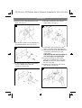
1.Loosely screw on nut (A1) with com-
pression ring (A2), see Fig. [2].
2.Ensure that the projections of the supply
pipes, (i.e. exposed beyond the wall sur-
face) have the correct length (13 - 18mm)
and distance (150mm).
3.Place the mixer body (E) with the elbows
and backplate (D) to the supply pipes.
4.Loosen set screw (D1), see Fig. [3].
5.Remove mixer body (E) from supply pipes
and hold backplate (D) in position.
1
A
B
C
1
2
m
m
2
D
E
A1
A2
3
D
E
D1
2
.
5
m
m
955751.book : i95575gb.fm Seite 7 Mittwoch, September 20, 2000 10:10 AM

8
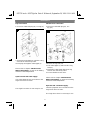
Installation
6.Mark the holes in the backplate for wall-
plugs, see Fig. [4].
7.Drill the holes (6mm) for the wallplugs (F)
and fit them into the wall, see Fig. [5].
8.Fix the backplate (D) with set screw (D1)
on top or bottom to the wall with
screws (G), see Fig. [6].
9.Slide the escutcheons (H) over the
supply pipes, see Fig. [7].
10.If flow limiter is mounted in the cold
water connection elbow install filter (J).
11.Slide the mixer body (E) with elbows and
compression nuts loosely over the
supply pipes.
The body must touch the backplate. If
not, check pipes for length again.
12.Fix the mixer body (E) to the back-
plate (D) by tightening set screw (D1).
Do not use excessive force to tighten
the set screw (D1).
13.Tighten the compression nuts (torque
min. 20 Nm), see Fig. [8].
4
5
F
6
G
D
D1
7
E
2
.
5
m
m
D1
H
J
D
8
2
4
m
m
955751.book : i95575gb.fm Seite 8 Mittwoch, September 20, 2000 10:10 AM

9
Installation
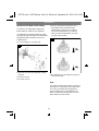
Pipe Connection
1.Close free outlet with plug (K), see Fig. [9].
2.Thread the outlet nipple (L) with the O-ring
seal into the mixer body outlet.
3.Insert pipe and tighten outlet nipple (L).
Please refer to chapter "Maximum Hot
Water Limit Setting" on page 10 for limiting
maximum outlet temperature.
Open hot and cold water supply.
Check the pipework and connections to the
single lever mixer for leaks.
The single lever mixer is now ready for use.
Shower Hose Connection
1.Close free outlet with plug (K), see
Fig. [10].
2.Remove O-ring seal (L1).
3.Turn outlet nipple (L) 180° and fit O-ring
seal (L1).
4.Thread the outlet nipple with the O-ring
seal into the mixer body outlet.
5.Connect flexible shower hose.
Please refer to chapter "Maximum Hot
Water Limit Setting" on page 10 for limiting
maximum outlet temperature.
Open hot and cold water supply.
Check the pipework and connections to the
single lever mixer for leaks.
The single lever mixer is now ready for use.
9
K
L
2
4
m
m
2
4
m
m
2
4
m
m
L
2
4
m
m
L1
K
2
4
m
m
10
1.
2.
3.
180°
955751.book : i95575gb.fm Seite 9 Mittwoch, September 20, 2000 10:10 AM

10
Installation
Maximum Hot Water Limit Setting
On delivery, the adjustable temperature
limiter (fitted as standard) is inoperative.
On applications requiring limiting the mixer
opening from full hot position, the adjustable
temperature limiter must be reset as de-
scribed below.
1.Lever out plug (O), see Fig. [11].
2.Remove set screw (P) with 3mm socket
spanner.
3.Pull off lever (R).
4.Unscrew cap (S).
5.Remove temperature limiter (M) and,
depending on the maximum water
temperature required, turn clockwise
(to increase temperature) or anticlock-
wise (to reduce temperature) and refit,
see Figs. [11] and [12].
6.Reinstall lever as described in Fig. [11] in
reversed direction.
Note:
A maximum temperature setting accurate to
the degree is not possible since differences
in hot and cold water flow temperatures,
pressure differences and installation con-
ditions all affect the temperature of mixed
water delivered at the outlet.
11
R
O
T
S
P
3
m
m
12
955751.book : i95575gb.fm Seite 10 Mittwoch, September 20, 2000 10:10 AM

11
Maintenance
Ceramic Cartridge
1.Shut off hot and cold water supply!
2.Lever out plug (O), see Fig. [13].
3.Remove set screw (P) with 3mm socket
spanner
4.Pull off lever (R).
5.Unscrew cap (S).
6.Pull off temperature limiter (T) and note
position.
7.Remove screws (U) and detach complete
cartridge (V).
8.Change either the complete cartridge (V)
or seals (V1).
Assemble in reverse order.
Make sure that the cartridge seals (V1)
engage in the grooves on the housing.
Fit screws (U) and tighten evenly and
alternately.
Check, clean and if necessary replace parts.
Only genuine GROHE replacement parts
must be used.
13
O
P
S
T
U
V
R
V1
3
m
m
955751.book : i95575gb.fm Seite 11 Mittwoch, September 20, 2000 10:10 AM

12
Care
Trouble Shooting
We want to ensure that you get long-lasting
satisfaction and pleasure from your GROHE
fitting. Therefore, please read the following
care instructions because damage to the
surface and underlying material resulting
from improper treatment is not covered by
our guarantee.
Do not use any abrasive sponges or scou-
ring agents for cleaning. We also advise not
to use cleaning agents containing solvent or
acid, limescale removers, household vinegar
and cleaning agents with acetic acid. They
are aggressive to the surface and will leave
your fitting dull and scratched. As the for-
mulations of commercially available cleaning
agents frequently change, we cannot gua-
rantee they will provide the gentle care our
fitting deserves.
Clean the fitting with a little soap and a moist
cloth only, then simply rinse off and wipe dry.
You can avoid lime spots by drying the fitting
each time it is used. If lime deposits do oc-
cur, remove them with Grohclean (ref. no.
18 078), our environment-friendly cleaning
liquid. Grohclean is specially formulated to
gently clean the surface of our fittings.
Problem Cause Remedy
Cold water on position
hot and vice versa
Hot and cold water supplies have
been connected in reverse
Rotating ceramic cartridge not
possible, change installation
Range of temperature
adjustment restricted
High pressure difference between
hot and cold water supply
Greater than 5 bar, fit pressure
reducing valve
More than 1 bar between cold and
hot water supply install flow limiter
see chapter Exposed Installation
Shower insufficiently
hot
Adjustable temperature limiter
incorrectly set
Hot water supply temperature too
low
Refer to the instructions in chapter
Maximum Hot Water Limit
Setting
Check hot water source tempera-
ture setting
No flow of hot or cold
water
Either the hot or cold side is not
fully pressurized
Debris caught inside the inlet of
the cartridge
Be sure the system is fully
pressurized
Remove cartridge and flush out or
remove any debris lodged inside
the hot or cold inlets
955751.book : i95575gb.fm Seite 12 Mittwoch, September 20, 2000 10:10 AM

15
Guarantee
Guarantee declaration
Our products correspond to the valid tech-
nical and water supply standards as well as
the relevant approvals requirements. We
guarantee them to be free of design and
production faults at the time of delivery and
that with correct use and care in accordance
with our printed instructions they will function
reliably.
Guarantee period
- The guarantee is valid in private homes for
5 years from the purchase date. Proof of
purchase has to be provided when making
a guarantee claim.
- By use in commercial or institutional appli-
cations the guarantee is valid for 1 year
after first use. An extension of the
guarantee up to 5 years can be achieved
by showing that the product is
professionally maintained each year.
To make a guarantee claim, proof of pur-
chase or, the beginning of use is required.
The guarantee period is not renewed or in-
creased through supply of spare parts or
repair during the guarantee period. The
guarantee period for purchased spare parts
is the same as for original products.
Guarantee performance
A)During the whole guarantee period we will
correct all functional defects for which we
are responsible (limitations see E + F).
B)It is our option if we correct the defects by
repair or replacement.
C)During the above guarantee period we will
not charge for the cost of parts, travel,
working time, freight and packaging
needed to effect the correction of defects.
D)If we are not able to correct the defect we
are prepared to supply a replacement
product.
E)Deliberate or careless damage is not co-
vered by this guarantee. If the installation,
assembly or care instructions that were
valid at the time of installation are not fol-
lowed or the product is used for a purpose
other than that given in the written infor-
mation the guarantee declaration does not
apply. Problems caused by dirt, lime-scale
or aggressive cleaners are not covered by
the guarantee.
F)The guarantee becomes void if repairs are
not carried out competently or spare parts
of non GROHE origin are used.
G)Replaced parts become the property of
GROHE and are to be surrendered to our
service personnel or sent to our registered
offices.
Please enter date of purchase and installation here.
Our address
GROHE Limited
1, River Road
Barking,
Essex, IG11 OHD
GB
Tel.: 0208 / 594 72 92
Fax: 0208 / 594 88 98
© 2000 Friedrich Grohe AG & Co. KG
Friedrich Grohe AG & Co. KG · P.O. Box 1361 · 58653 Hemer/Germany
Tel. (0) 23 72 / 93 - 0 · Fax: (0) 23 72 / 93 13 22
955751.book : garant_uk.fm Seite 15 Mittwoch, September 20, 2000 10:10 AM
-
 1
1
-
 2
2
-
 3
3
-
 4
4
-
 5
5
-
 6
6
-
 7
7
-
 8
8
-
 9
9
-
 10
10
-
 11
11
-
 12
12


GROHE Avensys Installation Instructions And Operating Manual
- Category
- Sanitary ware
- Type
- Installation Instructions And Operating Manual
Ask a question and I''ll find the answer in the document
Finding information in a document is now easier with AI
Related papers
-
GROHE Avensys Installation Instructions And Operating Manual
-
-
GROHE 35 236 Installation Instructions And Operating Manual
-
-
-
-
-
-
-
GROHE 38 732 Operating instructions
Other documents
-
Duravit WA4210012 Specification Manual
-
-
ALFI BRAND AB7938-BN User manual
-
 MODONA BL32X-A Installation guide
-
 MODONA BL32L-A Installation guide
-
 MODONA F902X-A Installation guide
-
 MODONA F902L-A Installation guide
-
 MODONA F772-A Installation guide
-
Dometic OVN0250, OVG0250 Operating instructions
-
 Mizu 9512144 Installation guide


