
OPER ATOR'S MANUAL
MAN0003
SKID STEER
TILLER
TL52
TL73
TL84
Effective Serial Numbers:
TL52A 4200690202
TL73A 4300730102
TL84A 5600020102
(Rev. 7/4/2008)
Tested. Proven. Unbeatable.

2 Introduction
Gen’l (Rev. 2/19/2008)
TO THE DEALER:
Assembly and proper installation of this product is the responsibility of the Woods
®
dealer. Read manual instructions
and safety rules. Make sure all items on the Dealer’s Pre-Delivery and Delivery Check Lists in the Operator’s Manual
are completed before releasing equipment to the owner.
The dealer must complete the Product Registration online at the Woods Dealer Website or complete the mail-in
form included with the Operator’s Manual. If using the mail-in form, the dealer is to return the prepaid postage portion to
Woods, give one copy to the customer, and retain one copy. Failure to register the product does not diminish
customer’s warranty rights.
TO THE OWNER:
Read this manual before operating your Woods equipment. The information presented will prepare you to do a better and
safer job. Keep this manual handy for ready reference. Require all operators to read this manual carefully and become
acquainted with all adjustment and operating procedures before attempting to operate. Replacement manuals can be
obtained from your dealer. To locate your nearest dealer, check the Dealer Locator at www.WoodsEquipment.com, or in
the United States and Canada call 1-800-319-6637.
The equipment you have purchased has been carefully engineered and manufactured to provide dependable and
satisfactory use. Like all mechanical products, it will require cleaning and upkeep. Lubricate the unit as specified.
Observe all safety information in this manual and safety decals on the equipment.
For service, your authorized Woods dealer has trained mechanics, genuine Woods service parts, and the necessary
tools and equipment to handle all your needs.
Use only genuine Woods service parts. Substitute parts will void the warranty and may not meet standards required for
safe and satisfactory operation. Record the model number and serial number of your equipment in the spaces
provided:
Model: _______________________________ Date of Purchase: _____________________
Serial Number: (see Safety Decal section for location) ____________________________________
Provide this information to your dealer to obtain correct repair parts.
Throughout this manual, the term NOTICE is used to indicate that failure to observe can cause damage to equipment.
The terms CAUTION, WARNING, and DANGER are used in conjunction with the Safety-Alert Symbol (a triangle with
an exclamation mark) to indicate the degree of hazard for items of personal safety.

Introduction 3
MAN0003 (Rev. 11/30/2006)
TABLE OF CONTENTS
INTRODUCTION . . . . . . . . . . . . . . . . . . . . . . . . . . . . . . . . . . . . . . . . . . . . . . .2
GENERAL INFORMATION . . . . . . . . . . . . . . . . . . . . . . . . . . . . . . . . . . . . . . .4
SPECIFICATIONS. . . . . . . . . . . . . . . . . . . . . . . . . . . . . . . . . . . . . . . . . . . . . .4
SAFETY RULES . . . . . . . . . . . . . . . . . . . . . . . . . . . . . . . . . . . . . . . . . . . . . . .5
SAFETY DECALS . . . . . . . . . . . . . . . . . . . . . . . . . . . . . . . . . . . . . . . . . . . . . .8
OPERATION . . . . . . . . . . . . . . . . . . . . . . . . . . . . . . . . . . . . . . . . . . . . . . . . .10
TROUBLESHOOTING . . . . . . . . . . . . . . . . . . . . . . . . . . . . . . . . . . . . . . . . .13
SERVICE. . . . . . . . . . . . . . . . . . . . . . . . . . . . . . . . . . . . . . . . . . . . . . . . . . . .15
PARTS INDEX . . . . . . . . . . . . . . . . . . . . . . . . . . . . . . . . . . . . . . . . . . . . . . . .20
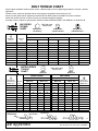
HYDRAULIC FITTING TORQUE CHART . . . . . . . . . . . . . . . . . . . . . . . . . . .26
QUICK COUPLER KITS . . . . . . . . . . . . . . . . . . . . . . . . . . . . . . . . . . . . . . . .27
BOLT TORQUE CHART . . . . . . . . . . . . . . . . . . . . . . . . . . . . . . . . . . . . . . . .30
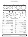
BOLT SIZE CHART & ABBREVIATIONS . . . . . . . . . . . . . . . . . . . . . . . . . . .31
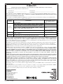
PRODUCT WARRANTY . . . . . . . . . . . . . . . . . . . . . . . . . . . . . . . . . . . . . . . .32
REPLACEMENT PARTS WARRANTY . . . . . . . . . . . . INSIDE BACK COVER

4 Introduction
MAN0003 (Rev. 11/30/2006)
GENERAL INFORMATION
The purpose of this manual is to assist you in operating
and maintaining your tiller. Read it carefully. It furnishes
information and instructions that will help you achieve
years of dependable performance. These instructions
have been compiled from extensive field experience
and engineering data. Some information may be gen-
eral in nature due to unknown and varying operating
conditions. However, through experience and these
instructions, you should be able to develop procedures
suitable to your particular situation.
The illustrations and data used in this manual were cur-
rent at the time of printing but, due to possible inline
production changes, your machine may vary slightly in
detail. We reserve the right to redesign and change the
machines as may be necessary without notification.
Throughout this manual, references are made to right
and left direction. These are determined by standing
behind the equipment facing the direction of forward
travel.
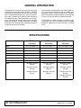
SPECIFICATIONS
TL52 TL73 TL84
Dual Direct Dual Direct Dual Direct
Motor Char-Lynn 2000 - 18.7 Char-Lynn 2000 - 18.7 Ross ME180405 AAAB
Maximum Pressure 3300 psi (228 bars) 3300 psi (228 bars) 5000 psi (245 bars)
Working Depth 0 - 6 Inches 0 - 6 Inches 0 - 6 Inches
Working Width 52 Inches (1321 mm) 73 Inches (1854 mm) 84 Inches (2134 mm)
Overall Width 60 Inches (1524 mm) 86 Inches (2184 mm) 97 Inches (2462 mm)
Overall Length 44 Inches (1118 mm) 44 Inches (1118 mm) 44 Inches (1118 mm)
Tines 28 36 40
RPM @12 gpm (46 lpm)
148 rpm
@15 gpm (76 lpm)
247 rpm
@20 gpm (76 lpm)
247 rpm
@15 gpm (57 lpm)
185 rpm
@25 gpm (95 lpm)
309 rpm
@25 gpm (95 lpm)
432 rpm
@18 gpm (69 lpm)
22 rpm
@32 gpm (122 lpm)
395 rpm
@32 gpm (122 lpm)
432 rpm
@40 gpm (152 lpm)
540 rpm

Safety 5
Alitec Tiller SR (Rev. 11/30/2006)
INSTALLATION
Hydraulics must be connected as instructed in
this manual. Do not substitute parts, modify, or
connect in any other way.
After connecting hoses, check that all control
lever positions function as instructed in the Opera-
tor's Manual. Do not put into service until control
lever and equipment movements are correct.
TRAINING
Safety instructions are important! Read all
attachment and power unit manuals; follow all
safety rules and safety decal information. (Replace-
ment manuals and safety decals are available from
your dealer. To locate your nearest dealer, check
the Dealer Locator at www.WoodsEquipment.com,
or in the United States and Canada call 1-800-319-
6637.) Failure to follow instructions or safety rules
can result in serious injury or death.
If you do not understand any part of this manual
and need assistance, see your dealer.
Know your controls and how to stop engine and
attachment quickly in an emergency.
Operators must be instructed in and be capable
of the safe operation of the equipment, its attach-
ments, and all controls. Do not allow anyone to
operate this equipment without proper instructions.
Keep hands and body away from pressurized
lines. Use paper or cardboard, not hands or other
body parts to check for leaks. Wear safety goggles.
Hydraulic fluid under pressure can easily penetrate
skin and will cause serious injury or death.
Make sure that all operating and service person-
nel know that if hydraulic fluid penetrates skin, it
must be surgically removed as soon as possible by
a doctor familiar with this form of injury or gan-
grene, serious injury, or death will result. CON-
TACT A PHYSICIAN IMMEDIATELY IF FLUID
ENTERS SKIN OR EYES. DO NOT DELAY.
Never allow children or untrained persons to
operate equipment.
PREPARATION
Check that all hardware is properly installed.
Always tighten to torque chart specifications
unless instructed otherwise in this manual.
Counterweight ballast may be required for
machine stability. Check your power unit manual or
contact your dealer.
Air in hydraulic systems can cause erratic oper-
ation and allows loads or equipment components
to drop unexpectedly. When connecting equipment
or hoses or performing any hydraulic maintenance,
purge any air in hydraulic system by operating all
hydraulic functions several times. Do this before
putting into service or allowing anyone to
approach the equipment.
After connecting hoses, check that all control
lever positions function as instructed in the Opera-
tor's Manual. Do not put into service until control
lever and equipment movements are correct.
Protective hose sleeves must cover all hydrau-
lic hoses within 20 inches of the operator and be
secured onto metal hose fittings. Replace hoses or
sleeves if damaged or if protective sleeve cannot
be properly positioned or secured.
Make sure all hydraulic hoses, fittings, and
valves are in good condition and not leaking before
starting power unit or using equipment. Check and
route hoses carefully to prevent damage. Hoses
must not be twisted, bent sharply, kinked, frayed,
pinched, or come into contact with any moving
parts. Operate moveable components through full
operational range to check clearances. Replace
any damaged hoses immediately.
Always wear relatively tight and belted clothing
to avoid getting caught in moving parts. Wear
sturdy, rough-soled work shoes and protective
equipment for eyes, hair, hands, hearing, and head;
and respirator or filter mask where appropriate.
(Safety Rules continued on next page)
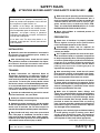
Safety is a primary concern in the design and
manufacture of our products. Unfortunately, our
efforts to provide safe equipment can be erased
by an operator’s single careless act.
In addition to the design and configuration of
equipment, hazard control and accident preven-
tion are dependent upon the awareness, concern,
judgement, and proper training of personnel
involved in the operation, transport, maintenance
and storage of equipment.
It has been said “The best safety device is an
informed, careful operator.” We ask you to be that
kind of operator.
SAFETY RULES
ATTENTION! BECOME ALERT! YOUR SAFETY IS INVOLVED!

6 Safety
Alitec Tiller SR (Rev. 11/30/2006)
(Safety Rules continued from previous page)
Be sure attachment is properly secured,
adjusted, and in good operating condition. Coupler
lockpins must be fully extended and properly
engaged into attachment retaining slots.
Power unit must be equipped with ROPS and
seat belt/operator restraint. Keep seat belt/operator
restraint securely fastened/engaged. Falling off
power unit can result in death from being run over
or crushed. Keep ROPS systems in place at all
times.
Make sure all safety decals are installed.
Replace if damaged. (See Safety Decals section for
location.)
Make sure shields and guards are properly
installed and in good condition. Replace if damaged.
Inspect and clear area of stones, branches, or
other hard objects that might be thrown, causing
injury or damage.
OPERATION
Improper operation can cause the machine to
tip or roll over and cause injury or death.
• Keep power unit lift arms and attachment as
low as possible.
• Do not travel or turn with power unit lift arms
and attachment raised.
• Turn only on level ground.
• Go up and down slopes, not across them.
• Keep the heavy end of the machine uphill.
• Do not overload the machine.
Never use attachment to carry loads that exceed
the rated operating capacity or other specifications
of the power unit. Check your power unit manual or
see your dealer for rated operating capacity.
Exceeding this capacity can cause machine to tip,
roll over, or present other hazards that can cause
injury or death.
Do not allow bystanders in the area when oper-
ating, attaching, removing, assembling, or servic-
ing equipment.
Contact with high voltage, overhead power
lines, underground cables, gas lines, and other
hazards can cause serious injury or death from
electrocution, explosion, or fire.
Keep bystanders away from equipment.
Never direct discharge toward people, animals,
or property.
Do not operate or transport equipment while
under the influence of alcohol or drugs.
Operate only in daylight or good artificial light.
Keep hands, feet, hair, and clothing away from
equipment while engine is running. Stay clear of all
moving parts.
Always comply with all state and local lighting
and marking requirements.
Do not allow riders. Do not lift or carry anybody
on the power unit or attachments.
Always sit in power unit seat when operating
controls or starting engine. Securely fasten seat
belt/operator restraint, place transmission in park
or neutral, engage brake and ensure all other con-
trols are disengaged before starting power unit
engine.
Look down and to the rear and make sure area
is clear before operating in reverse.
Use extreme care when working close to fences,
ditches, other obstructions, or on hillsides.
Do not operate or transport on steep slopes.
Do not stop, start, or change directions sud-
denly on slopes.
Use extreme care and reduce ground speed on
slopes and rough terrain.
Watch for hidden hazards on the terrain during
operation.
Stop power unit and implement immediately
upon striking an obstruction. Dismount power unit,
using proper procedure. Inspect and repair any
damage before resuming operation.
Leak down or failure of mechanical or hydraulic
system can cause equipment to drop.
Before making any adjustments on attachment,
stop engine and engage parking brake. Never
adjust or work on attachment while the power unit
or attachment is running.
(Safety Rules continued on next page)
SAFETY RULES
ATTENTION! BECOME ALERT! YOUR SAFETY IS INVOLVED!

Safety 7
Alitec Tiller SR (Rev. 11/30/2006)
(Safety Rules continued from previous page)
MAINTENANCE
Before leaving operator's seat, follow power
unit manual instructions. Lower lift arms and put
attachment on the ground. Stop engine, remove
key, engage brake, and remove seat belt/operator
restraint.
NEVER GO UNDERNEATH EQUIPMENT. Never
place any part of the body underneath equipment
or between moveable parts even when the engine
has been turned off. Hydraulic system leak-down,
hydraulic system failures, mechanical failures, or
movement of control levers can cause equipment
to drop or rotate unexpectedly and cause severe
injury or death.
• Service work does not require going under-
neath.
• Read Operator's Manual for service instruc-
tions or have service performed by a qualified
dealer.
Do not modify or alter or permit anyone else to
modify or alter the equipment or any of its compo-
nents in any way.
Your dealer can supply original equipment
hydraulic accessories and repair parts. Substitute
parts may not meet original equipment specifica-
tions and may be dangerous.
Do not allow bystanders in the area when oper-
ating, attaching, removing, assembling, or servic-
ing equipment.
Never perform service or maintenance with
engine running.
Keep all persons away from operator control
area while performing adjustments, service, or
maintenance.
Tighten all bolts, nuts, and screws to torque
chart specifications. Check that all cotter pins are
installed securely to ensure equipment is in a safe
condition before putting unit into service.
Make sure all safety decals are installed.
Replace if damaged. (See Safety Decals section for
location.)
Make sure shields and guards are properly
installed and in good condition. Replace if damaged.
Do not disconnect hydraulic lines until all sys-
tem pressure is relieved. Lower unit to ground,
stop engine, and operate all hydraulic control
levers.
Leak down or failure of mechanical or hydraulic
system can cause equipment to drop.
STORAGE
Follow manual instructions for storage.
Keep children and bystanders away from stor-
age area.
SAFETY RULES
ATTENTION! BECOME ALERT! YOUR SAFETY IS INVOLVED!

8 Safety
MAN0003 (Rev. 11/30/2006)
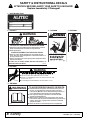
5 - PN 19924
Check for leaks with cardboard; never use hand.
Before loosening fittings: lower load, release pressure, and
be sure oil is cool.
Consult physician immediately if skin penetration occurs.
WARNING
19924-B
WARNING
54519-B
FALLING OFF CAN RESULT IN BEING RUN OVER.
■ Skid steer must have ROPS and seat belt/operator restraint.
Keep seat belt/operator restraint securely fastened.
■ Never allow riders.
RAISED EQUIPMENT CAN DROP AND CRUSH.
■ Never go under raised equipment or raised skid steer lift
arms. They can drop from hydraulic or mechanical failure, or
moving control levers.
■ Service work does not require going under equipment. Read
manual instructions.
FALLING OFF OR GOING UNDER MACHINE CAN RESULT IN
SERIOUS INJURY OR DEATH.
2 - PN 54519 3 - PN D0200
D0209
4 - PN D0209
1 - Serial Number Plate
TO AVOID SERIOUS INJURY OR DEATH:
Read attachment and power unit manuals before you use,
service, or repair machine. Follow all safety rules and
instructions. (Manuals can be obtained from your dealer, or
in the United States and Canada call 1-800-319-6637.)
Use only when sitting in operator's seat with seat belt/
operator restraint fastened.
Before leaving operator's seat, follow power unit manual
instructions, lower lift arms and attachment to ground, stop
engine, remove key, engage brake, and remove seat belt/
operator restraint.
Never let children or untrained persons run equipment.
WARNING
D0404-C
6 - PN D0404
SAFETY & INSTRUCTIONAL DECALS
ATTENTION! BECOME ALERT! YOUR SAFETY IS INVOLVED!
Replace Immediately If Damaged!
(Rev. 4/4/2008)

Safety 9
MAN0003 (Rev. 11/30/2006)
SAFETY & INSTRUCTIONAL DECALS
ATTENTION! BECOME ALERT! YOUR SAFETY IS INVOLVED!
Replace Immediately If Damaged!
BE CAREFUL!
Use a clean, damp cloth to clean safety decals. Avoid spraying too close to decals when using a
pressure washer; high-pressure water can enter through very small scratches or under edges of
decals causing them to peel or come off.
Replacement safety decals can be ordered free from your Woods dealer. To locate your nearest
dealer, check the Dealer Locator at www.WoodsEquipment.com, or in the United States and
Canada call 1-800-319-6637.
(Rev. 4/4/2008)

10 Operation
MAN0003 (Rev. 11/30/2006)
OPERATION
Safety instructions are important! Read all
attachment and power unit manuals; follow all
safety rules and safety decal information. (Replace-
ment manuals and safety decals are available from
your dealer. To locate your nearest dealer, check
the Dealer Locator at www.WoodsEquipment.com,
or in the United States and Canada call 1-800-319-
6637.) Failure to follow instructions or safety rules
can result in serious injury or death.
Power unit must be equipped with ROPS and
seat belt/operator restraint. Keep seat belt/operator
restraint securely fastened/engaged. Falling off
power unit can result in death from being run over
or crushed. Keep ROPS systems in place at all
times.
■ The operator is responsible for the safe opera-
tion of this equipment. Operators must be
instructed in and be capable of the safe operation
of the equipment, its attachments and all controls.
Do not allow anyone to operate this equipment
without proper instructions.
Skid steers must be equipped with an auxiliary
hydraulic system capable of supplying continuous
flow for hydraulic motor operation.
PRE-OPERATION CHECK LIST
Owner’s Responsibility
___ Review and follow all safety rules and decals.
See safety rules on page 5 and safety decals on
page 8.
___ Check that all safety decals are installed and in
good condition. Replace if damaged.
___ Check that all shields and guards are properly
installed and in good condition. Replace if dam-
aged.
___ Check that equipment is properly and securely
attached to skid steer.
___ Check that all hardware and cotter pins are prop-
erly installed and secured.
___ Do not allow riders.
___ Keep all bystanders away from equipment work-
ing area.
___ Check that all hydraulic hoses and fittings are in
good condition and not leaking before starting
power unit.
___ Check that hoses are not twisted, bent sharply,
kinked, frayed or pulled tight. Replace any dam-
aged hoses immediately.
___ Make sure power unit ROPS and seat belts are in
good condition. Keep seat belt securely fastened
during operation.
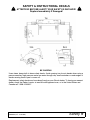
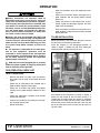
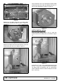
TILLER INSTALLATION
Read instructions in the skid steer operator’s manual
for connecting and removing attachment.
Place the couplers in the disengaged position as
shown in Figure 1. Rotate the skid steer attachment
slightly forward and fully lower the lift arms.
Figure 1.
Pull forward to the attachment as shown in Figure 2.
Make sure the outside of the skid steer attach (1) is
aligned with the inside of the tiller attach (2). Continue
to pull forward until the skid steer attach makes contact
with the tiller attach. Raise the skid steer arms until the
top of the skid steer attach contacts the top latch bar
(3) on the tiller.
DP1

Operation 11
MAN0003 (Rev. 11/30/2006)
Figure 2.
Roll the skid steer arms back until the tiller is com-
pletely off the ground. Engage the parking break on the
skid steer. Stop engine and relieve the back pressure in
the auxiliary hydraulic system. Exit the skid steer.
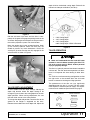
Move the coupler pins to the engaged position. Hook
up the auxiliary hydraulic hoses. Be sure they are
routed to prevent any hose interference. Check the
attach pins (4) to be sure they are fully engaged in the
attach bracket as shown in Figure 3.
Figure 3.
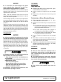
TILLER DEPTH ADJUSTMENT
All tiller models have four depth settings. Moving the
depth skid location allows the depth setting to be
changed. Figure 4 shows the cutting depth for the four
depth positions. When making adjustments, be sure
that both skids are set at the same position.
To change the depth skid position, lower the tiller to the
ground so the weight is supported on the tines.
Remove the two bolts from each depth skid. Adjust the
depth skid for the desired cutting depth. Reinstall the
two bolts and torque to 250 lbs-ft (325 N-m).
Figure 4.
TILLER OPERATION
■ Read and understand the tiller and skid steer
operator’s manuals before operating the tiller. Fail-
ure to do so may result in death, serious personal
injury or properly damage.
The tiller is a hydraulic powered attachment intended to
cultivate soil. The tiller attachment operation is bi-direc-
tional; it will operate with tines rotating in either direc-
tion.
The TL52 has an offset mounting configuration to allow
the right tracks to be covered when the skid steer
moves in reverse for finishing the tilling operation.
The performance of the tiller can vary significantly
depending upon the way it is used. The tiller attach-
ment requires a minimum hydraulic supply. For require-
ments on each model see specifications on page 4.
DP2
1
2
3
4
DP3
1. 5.50" Cutting Depth
2. 4.25" Cutting Depth
3. 2.25" Cutting Depth
6.00" Cutting Depth if Skid is Removed

12 Operation
MAN0003 (Rev. 11/30/2006)
NOTICE
■ To avoid tiller and motor damage, stop prime
mover hydraulic flow. Allow tiller to stop com-
pletely before changing direction of rotation.
For maximum productivity and to maintain optimal
operation, keep chassis free of residue build up and
replace worn or broken tines.
Never raise the attachment more than 24" off the
ground. When loading, keep the attachment as low to
ramps and trailers as possible.
For finish tilling operation, the tiller may be operated in
the reverse direction with the tines rotating in a clock-
wise direction when viewed from the left side of the
machine.
Roll the skid steer arms fully back and lower the arms
completely. Activate auxiliary hydraulics and make sure
the tines are rotating in the desired direction. Bring skid
steer to high idle, slowly tilt the tiller forward until the
depth skids contact the ground. Move the skid steer in
the desired direction of travel.
TRANSPORT
NOTICE
■ When transporting the attachment, be sure the
tines do not contact the ground as this may cause
the drum to turn resulting in damage to the motor.
Roll the skid steer arms fully back and raise the attach-
ment 12" to 15" from the ground. Avoid excessive
ground speed and sudden maneuvers. Never raise the
attachment more than 24" off the ground. When load-
ing, keep the attachment as low to ramps and trailers
as possible.
Improper operation can cause the machine to
tip or roll over and cause injury or death.
• Keep power unit lift arms and attachment as
low as possible.
• Do not travel or turn with power unit lift arms
and attachment raised.
• Turn only on level ground.
• Go up and down slopes, not across them.
• Keep the heavy end of the machine uphill.
• Do not overload the machine.
Look down and to the rear and make sure area
is clear before operating in reverse.
CLEANING
After Each Use
● Remove large debris such as clumps of dirt, grass,
crop residue, etc. from machine.
● Inspect machine and replace worn or damaged
parts.
● Replace any safety decals that are missing or not
readable.
Periodically or Before Extended Storage
● Clean large debris such as clumps of dirt, grass,
crop residue, etc. from machine.
● Remove the remainder using a low-pressure water
spray.
1. Be careful when spraying near scratched or torn
safety decals or near edges of decals as water
spray can peel decal off surface.
2. Be careful when spraying near chipped or
scratched paint as water spray can lift paint.
3. If a pressure washer is used, follow the advice
of the pressure washer manufacturer.
● Inspect machine and replace worn or damaged
parts.
● Sand down scratches and the edges of areas of
missing paint and coat with spray paint of matching
color (purchase from your dealer).
● Replace any safety decals that are missing or not
readable (supplied free by your dealer). See Safety
Decals section for location drawing.
STORAGE
NOTICE
■ Store the tiller inside when possible. If this is
not possible, store the tiller on a pallet. Be sure the
tiller is stored off the ground to protect the cou-
plers and hoses.
■ The supply and return hoses must always be
secured with quick disconnects or caps to prevent
loss of fluids and contamination.
■ Keep children and bystanders away from stor-
age area.

Troubleshooting 13
MAN0003 (Rev. 11/30/2006)
TROUBLESHOOTING
PROBLEM POSSIBLE CAUSES SOLUTION
Drum will not rotate Auxiliary hoses are not hooked up
to skid steer
Inspect connections visually (make
sure QD’s are fully engaged).
There is an obstruction in one or
both of the auxiliary hoses
Remove and inspect hoses
visually.
One or more seals on the motor
have failed
Contact dealer.
Skid steer auxiliary hydraulics are
not operating properly
Refer to skid steer owner’s
manual.
Motor hoses are not plumbed
correctly
See “Hydraulic Assembly TL52” on
page 22. Verify correct hose
routing.
Drum rotates sluggishly Insufficient hydraulic flow from the
skid steer
Refer to skid steer owner’s
manual.
The hydraulic oil filter on the skid
steer is dirty
Refer to skid steer owner’s
manual.
One or more seals on the motor
have failed
Contact dealer.
Motor operates, but the drum does
not rotate
Cross bolt on coupler is sheared Inspect visually and repair as
needed.
Coupler splines are stripped Inspect visually and repair as
needed.
Motor shaft splines are stripped. Inspect visually and repair as
needed.
Oil is leaking from the motor area. One or more seals on the motor
have failed.
Contact dealer.
O-rings on fitting are damaged Visually inspect o-rings and
replace as needed.
Fittings are loose or damaged Refer to skid steer owner’s
manual.
Hydraulic hoses are loose or
damaged
Refer to skid steer owner’s
manual.
Insufficient cutting power One or more seals on motor have
failed
Contact dealer.
Oil filter on the skid steer is dirty Refer to skid steer owner’s
manual.
Insufficient auxiliary flow from skid
steer
Refer to skid steer owner’s
manual.
Relief valve on skid steer is not set
properly
Refer to skid steer owner’s
manual.

14 Troubleshooting
MAN0003 (Rev. 11/30/2006)
TROUBLESHOOTING
PROBLEM POSSIBLE CAUSES SOLUTION
Excessive oil temperature Obstruction in one or both auxiliary
hoses
Visually inspect and replace hoses
as necessary.
Hydraulic oil level on skid steer is
low
Refer to skid steer owner’s
manual.
Hydraulic oil in skid steer is dirty Refer to skid steer owner’s
manual.
Hydraulic oil filter on skid steer is
dirty
Refer to skid steer owner’s
manual.
Relief valve on skid steer is not set
properly
Refer to skid steer owner’s
manual.
Insufficient tilling power The tines are worn or bent Replaced damaged tines.
Debris has built up inside the
chassis
Clean debris from inside of
chassis.
Insufficient hydraulic flow from the
skid steer
Refer to skid steer owner’s
manual.
The hydraulic oil filter on the skid
steer is dirty
Refer to skid steer owner’s
manual.
One or more seals on the motor
have failed
Contact dealer.

Service 15
MAN0003 (Rev. 11/30/2006)
SERVICE
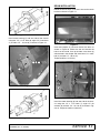
DRUM REMOVAL
Rotate the tiller so it rests on the attach wings as
shown in Figure 5. Use a hoist to support the drum at
the midpoint.
Figure 5.
Remove the two depth skid bolts (1) and four motor
housing bolts (2) from one side as shown in Figure 6.
Figure 6.
Remove the depth skid and the motor housing from
one side as shown in Figure 7. Slide the drum off
remaining motor shaft.
Figure 7.
Remove the coupler bolt (3) and the coupler (4) from
both sides of the drum as shown in Figure 8.
Figure 8.
MOTOR REMOVAL
Rotate the tiller so it rests on the attach wings as
shown in Figure 9. Use a hoist to support the drum at
the midpoint.
DP4
DP5
1
2
4
3

16 Service
MAN0003 (Rev. 11/30/2006)
Figure 9.
Remove the two depth skid bolts (1) and four motor
housing bolts (2) from one side as shown in Figure 10.
Figure 10.
Remove the depth skid and motor housing. Place the
motor housing in vice (3) as shown in Figure 11.
Figure 11.
Use an extension and a 1/2” twelve point socket to hold
motor bolts from the inside and remove the four 1/2”
nuts (4) from the bottom as shown in Figure 12.
Figure 12.
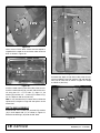
MOTOR INSTALLATION
Place the motor housing into a vice (1). Install the
motor and orient the motor ports (2) as shown in Figure
13.
Figure 13.
Install four 1/2” - 20 x 1-1/2” twelve-point bolts (3) and
four 1/2” - 20 (4) nuts as shown in Figure 14 and Figure
16. While using an extension and 1/2” twelve-point
socket, hold bolts from the inside and torque nuts to 85
lbs-ft. (115 N-m).
DP4
DP5
1
2
3
DP8
4
DP9
DP8
2
1

Service 17
MAN0003 (Rev. 11/30/2006)
Figure 14. TL52 and TL73
Install motor housing (5) into one side of the chassis
using four 1/2” x 1-1/2” bolts (6), eight 1/2” flat washers
(7) and four 1/2” - 13 nuts (8) as shown in Figure 15.
Figure 15.
Figure 16. TL84
DRUM INSTALLATION
Rotate the tiller chassis (1) so that it rests on the attach
bracket as shown in Figure 17.
Figure 17.
Insert one coupler (2) into each end of the drum as
shown in Figure 18. Make sure the end nearest the
hole is to the inside. Line up the hole in the drum (3)
with the hole in the coupler and install one 1/2" x 3-3/4"
bolt (4) and one 1/2" - 20 nut (5).
Torque to 85 lbs-ft (115 N-m).
Figure 18.
Install the motor housing (6) into one side of the chas-
sis using four 1/2" x 1-1/2" bolts (7), eight 1/2" flat
washers (8) and four 1/2" - 13 nuts (9) as shown in Fig-
ure 19. Torque to 120 lbs-ft (163 N-m).
DP10
5
6
7
8
1
DP12
5
3
4
2
DP7

18 Service
MAN0003 (Rev. 11/30/2006)
Figure 19
Use a hoist to lift the drum. Make sure the coupler is
aligned with the motor shaft and insert motor shaft into
drum as shown in Figure 20.
Figure 20.
Install the motor housing into other side of the chassis.
Install the motor housing (6) into one side of the chas-
sis using four 1/2" x 1-1/2" bolts (7), eight 1/2" flat
washers (8) and four 1/2" - 13 nuts (9) as shown in Fig-
ure 19. Torque to 120 lbs-ft (163 N-m).
Note: It may be necessary to rotate drum to allow the
splines on the coupler to align with the splines on the
motor shaft.
DEPTH SKID ASSEMBLY
Install two 5/8" x 4-1/2" bolts (14) and two 5/8" washers
(15) in each depth skid (17) as shown in Figure 21.
Slide the two bushings (16) onto the 5/8" bolts.
Figure 21.
Assemble the depth skid on either side of the chassis,
using an additional two 5/8" washers (18) and two 5/8"
nuts (19) for each side as shown in Figure 22. Torque
to 240 lbs-ft (325 N-m).
Figure 22.
DP10
6
7
8
9
DP6
DP12
15
17
16
14
DP13
19
18

Service 19
MAN0003 (Rev. 11/30/2006)
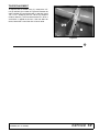
TINE REPLACEMENT
To replace worn or broken tines (1), remove the 1/2"
nut (3) and bolt (2) as shown in Figure 23. Remove the
worn or broken tine and replace with a new tine. Install
1/2" x 1-1/2" - 20 bolt (2) and 1/2" - 20 nut (3). Torque to
50 lbs-ft (68 N-m). The tine should rotate ±15° when a
small force is applied to the tine. If the tine does not
rotate, loosen the nut until the tine is free to rotate.
Figure 23.
3
1
2

20 Parts
MAN0003 (Rev. 11/30/2006)
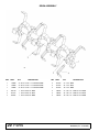
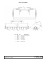
DRUM ASSEMBLY
REF PART QTY DESCRIPTION
1 59000 24 Bolt, 1/2 NF x 1-1/2 GR8 ZP TL52
1 59000 24 Bolt, 1/2 NF x 1-1/2 GR8 ZP TL73
1 59000 24 Bolt, 1/2 NF x 1-1/2 GR8 ZP TL84
2 105170 1 Drum weld, 52" TL52
2 101913 1 Drum weld, 73" TL73
2 102402 1 Drum weld, 84" TL84
REF PART QTY DESCRIPTION
3 101533 24 Tine, TL52
3 101533 36 Tine, TL73
3 101533 40 Tine, TL84
4 B0816 24 Nut, 1/2 - 20 Stover PLT TL52
4 B0816 36 Nut, 1/2 - 20 Stover PLT TL73
4 B0816 40 Nut, 1/2 - 20 Stover PLT TL84
(Rev. 4/4/2008)
Page is loading ...
Page is loading ...
Page is loading ...
Page is loading ...
Page is loading ...
Page is loading ...
Page is loading ...
Page is loading ...
Page is loading ...
Page is loading ...
Page is loading ...
Page is loading ...
Page is loading ...
Page is loading ...
-
 1
1
-
 2
2
-
 3
3
-
 4
4
-
 5
5
-
 6
6
-
 7
7
-
 8
8
-
 9
9
-
 10
10
-
 11
11
-
 12
12
-
 13
13
-
 14
14
-
 15
15
-
 16
16
-
 17
17
-
 18
18
-
 19
19
-
 20
20
-
 21
21
-
 22
22
-
 23
23
-
 24
24
-
 25
25
-
 26
26
-
 27
27
-
 28
28
-
 29
29
-
 30
30
-
 31
31
-
 32
32
-
 33
33
-
 34
34


Woods Equipment TL84 User manual
- Category
- Mini tillers
- Type
- User manual
Ask a question and I''ll find the answer in the document
Finding information in a document is now easier with AI
Related papers
Other documents
-
 T & S Brass & Bronze Works B-0199-29 Datasheet
-
 Hansen 5300 Operating instructions
-
 Land Pride SRT User manual
-
Toro Auxiliary Valve Kit, RT600 Traction Unit Installation guide
-
Woods SG60B User manual
-
Kubota AP-SRT76 User manual
-
-
-
-


