Page is loading ...

OPER ATOR'S MANUAL
REAR BLADE &
LANDSCAPE RAKE
MAN0169
Rev. 3/09/2010
Tested. Proven. Unbeatable.
RBC60
LRC60

2 Introduction
Gen’l (Rev. 3/5/2010)
TO THE DEALER:
Assembly and proper installation of this product is the responsibility of the Woods
®
dealer. Read manual instructions
and safety rules. Make sure all items on the Dealer’s Pre-Delivery and Delivery Check Lists in the Operator’s Manual
are completed before releasing equipment to the owner.
The dealer must complete the online Product Registration form at the Woods Dealer Website which certifies that
all Dealer Check List items have been completed. Please contact your dealer to complete this form. Dealers can
register all Woods product at dealer.WoodsEquipment.com under Product Registration.
Failure to register the product does not diminish customer’s warranty rights.
TO THE OWNER:
Read this manual before operating your Woods equipment. The information presented will prepare you to do a better and
safer job. Keep this manual handy for ready reference. Require all operators to read this manual carefully and become
acquainted with all adjustment and operating procedures before attempting to operate. Replacement manuals can be
obtained from your dealer. To locate your nearest dealer, check the Dealer Locator at www.WoodsEquipment.com, or in
the United States and Canada call 1-800-319-6637.
The equipment you have purchased has been carefully engineered and manufactured to provide dependable and
satisfactory use. Like all mechanical products, it will require cleaning and upkeep. Lubricate the unit as specified.
Observe all safety information in this manual and safety decals on the equipment.
For service, your authorized Woods dealer has trained mechanics, genuine Woods service parts, and the necessary
tools and equipment to handle all your needs.
Use only genuine Woods service parts. Substitute parts will void the warranty and may not meet standards required for
safe and satisfactory operation. Record the model number and serial number of your equipment in the spaces
provided:
Model: _______________________________ Date of Purchase: _____________________
Serial Number: (see Safety Decal section for location) ____________________________________
Provide this information to your dealer to obtain correct repair parts.
Throughout this manual, the term NOTICE is used to indicate that failure to observe can cause damage to equipment.
The terms CAUTION, WARNING, and DANGER are used in conjunction with the Safety-Alert Symbol (a triangle with
an exclamation mark) to indicate the degree of hazard for items of personal safety.

Introduction 3
MAN0169 (Rev. 5/6/2005)
TABLE OF CONTENTS
INTRODUCTION . . . . . . . . . . . . . . . . . . . . . . . . . . . . INSIDE FRONT COVER
SPECIFICATIONS . . . . . . . . . . . . . . . . . . . . . . . . . . . . . . . . . . . . . . . . . . . . . 4
GENERAL INFORMATION . . . . . . . . . . . . . . . . . . . . . . . . . . . . . . . . . . . . . . 4
SAFETY RULES . . . . . . . . . . . . . . . . . . . . . . . . . . . . . . . . . . . . . . . . . . . . . . 5
SAFETY DECALS . . . . . . . . . . . . . . . . . . . . . . . . . . . . . . . . . . . . . . . . . . . . . 7
OPERATION . . . . . . . . . . . . . . . . . . . . . . . . . . . . . . . . . . . . . . . . . . . . . . . . . 9
MAINTENANCE . . . . . . . . . . . . . . . . . . . . . . . . . . . . . . . . . . . . . . . . . . . . . 13
ASSEMBLY . . . . . . . . . . . . . . . . . . . . . . . . . . . . . . . . . . . . . . . . . . . . . . . . . 15
DEALER CHECK LISTS . . . . . . . . . . . . . . . . . . . . . . . . . . . . . . . . . . . . . . . 19
PARTS
ASSEMBLY . . . . . . . . . . . . . . . . . . . . . . . . . . . . . . . . . . . . . . . . . . 20
MANUAL STORAGE TUBE KIT (OPTIONAL) . . . . . . . . . . . . . . . . 21
SKID SHOE AND TAIL WHEEL (OPTIONAL) . . . . . . . . . . . . . . . . 22
CATEGORY 1 QUICK HITCH BUSHING KIT (OPTIONAL). . . . . . 22
CATEGORY 0 / 1 HITCH PIN KIT (OPTIONAL) . . . . . . . . . . . . . . 23
BOLT TORQUE CHART . . . . . . . . . . . . . . . . . . . . . . . . . . . . . . . . . . . . . . . 24
BOLT SIZE CHART & ABBREVIATIONS . . . . . . . . . . . . . . . . . . . . . . . . . . 25
PRODUCT WARRANTY . . . . . . . . . . . . . . . . . . . . . . . . . . . . . . . . . . . . . . . 24
REPLACEMENT PARTS WARRANTY . . . . . . . . . . . . INSIDE BACK COVER
Si no lee Ingles, pida ayuda a
alguien que si lo lea para que le
traduzca las medidas de seguridad.
LEA EL INSTRUCTIVO!
!

4 Introduction
MAN0169 (Rev. 5/6/2005)
SPECIFICATIONS
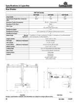
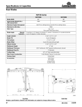
RBC60 LRC60
Overall Width 60 inches 60 inches
Weight 182 lbs. 177 lbs.
Moldboard Thickness 7-gauge -----------
Cutting Edge 1/2" x 6" x 60" Reversible ----------
Teeth ---------- 30 - 5/16" x 1"
HT High Carbon Tines
Position 360° Pivot 360° Pivot
Offset - Left or Right 12 inches -----------
Angle - Left or Right 15° or 30° 15° or 30°
Pitch Adjustment Controlled by top link Controlled by top link
Tractor Rating Max. Engine 25 hp Max. Engine 25 hp
Tractor 3-Point Cat 0 or 1 Cat 0 or 1
Options Skid Shoe & Cat 1 Gauge Wheels & Cat 1
Quick Hitch Bushing Kit Quick Hitch Bushing Kit
Quick Hitch Cat 1 Cat 1
Parking Stand Included Included
GENERAL INFORMATION
The purpose of this manual is to assist you in operating
and maintaining your equipment. Read it carefully. It
furnishes information and instructions that will help you
achieve years of dependable performance.
These instructions have been compiled from extensive
field experience and engineering data. Some informa-
tion may be general in nature, due to unknown and
varying operating conditions. However, through experi-
ence and these instructions, you should be able to
develop procedures suitable to your particular situa-
tion.
The illustrations and data used in this manual were cur-
rent at the time of printing. However, due to possible
inline production changes, your machine may vary
slightly in detail. We reserve the right to redesign and
change the machines as may be necessary without
notification.
Throughout this manual, references are made to right
and left directions. These are determined by standing
behind the tractor facing the direction of forward travel.
(Rev 3/9/2010)

Safety 5
RBC60/LRC60 SR (Rev. 8/26/2005)
TRAINING
Safety instructions are important! Read all
attachment and power unit manuals; follow all
safety rules and safety decal information. (Replace-
ment manuals and safety decals are available from
your dealer. To locate your nearest dealer, check
the Dealer Locator at www.WoodsEquipment.com,
or in the United States and Canada call 1-800-319-
6637.) Failure to follow instructions or safety rules
can result in serious injury or death.
If you do not understand any part of this manual
and need assistance, see your dealer.
Know your controls and how to shut down
quickly in an emergency.
Operators must be instructed in and be capable
of the safe operation of the equipment, its attach-
ments, and all controls. Do not allow anyone to
operate this equipment without proper instructions.
Never allow children or untrained persons to
operate equipment.
PREPARATION
Check that all hardware is properly installed.
Always tighten to torque chart specifications
unless instructed otherwise in this manual.
Always wear relatively tight and belted clothing
to avoid entanglement in moving parts. Wear
sturdy, rough-soled work shoes and protective
equipment for eyes, hair, hands, hearing, and head;
and respirator or filter mask where appropriate.
Make sure attachment is properly secured,
adjusted, and in good operating condition.
Power unit must be equipped with ROPS or
ROPS cab and seat belt. Keep seat belt securely
fastened. Falling off power unit can result in death
from being run over or crushed. Keep foldable
ROPS systems in “locked up” position at all times.
Make sure all safety decals are installed.
Replace if damaged. (See Safety Decals section for
location.)
A minimum 20% of tractor and equipment
weight must be on the tractor front wheels when
attachments are in transport position. Without this
weight, front tractor wheels could raise up result-
ing in loss of steering. The weight may be attained
with front wheel weights, ballast in tires or front
tractor weights. Weigh the tractor and equipment.
Do not estimate.
OPERATION
Consult local utilities before working. Know
location of all underground cables, pipelines, over-
head wires, and other hazards in working area and
avoid contact.
Keep bystanders away from equipment.
Do not operate or transport equipment while
under the influence of alcohol or drugs.
Operate only in daylight or good artificial light.
Keep hands, feet, hair, and clothing away from
equipment while engine is running. Stay clear of all
moving parts.
Always comply with all state and local lighting
and marking requirements.
Before transporting, pivot the unit so red reflec-
tors face the rear.
Never allow riders on power unit or attachment.
Power unit must be equipped with ROPS or
ROPS cab and seat belt. Keep seat belt securely
fastened. Falling off power unit can result in death
from being run over or crushed. Keep foldable
ROPS systems in “locked up” position at all times.
Always sit in power unit seat when operating
controls or starting engine. Securely fasten seat
belt, place transmission in neutral, engage brake,
and ensure all other controls are disengaged
before starting power unit engine.
Look down and to the rear and make sure area
is clear before operating in reverse.
Do not operate or transport on steep slopes.
(Safety Rules continued on next page)
Safety is a primary concern in the design and
manufacture of our products. Unfortunately, our
efforts to provide safe equipment can be wiped
out by an operator’s single careless act.
In addition to the design and configuration of
equipment, hazard control and accident preven-
tion are dependent upon the awareness, concern,
judgement, and proper training of personnel
involved in the operation, transport, maintenance
and storage of equipment.
It has been said “The best safety device is an
informed, careful operator.” We ask you to be that
kind of operator.
SAFETY RULES
ATTENTION! BECOME ALERT! YOUR SAFETY IS INVOLVED!

6 Safety
RBC60/LRC60 SR (Rev. 8/26/2005)
(Safety Rules continued from previous page)
Do not stop, start, or change directions sud-
denly on slopes.
Use extreme care and reduce ground speed on
slopes and rough terrain.
Watch for hidden hazards on the terrain during
operation.
Stop power unit and equipment immediately
upon striking an obstruction. Turn off engine,
remove key, inspect, and repair any damage before
resuming operation.
Before changing positions of manual swing, tilt,
or angle positions:
• Park tractor on level ground, apply parking
brake, level implement boom, shut off tractor,
and remove key.
• Make manual changes slowly and carefully
to prevent hazardous movement of mecha-
nisms.
• Never stand in positions where you could
become entrapped during adjustment changes
or if the 3-point hitch suddenly lowers.
Always secure lock pins with safety pins to pre-
vent lock pins from bumping out of the positioning
holes. Failure to do so may result in accidents and/
or damage to blade.
Before dismounting power unit or performing
any service or maintenance, follow these steps:
disengage power to equipment, lower the 3-point
hitch and all raised components to the ground,
operate valve levers to release any hydraulic pres-
sure, set parking brake, stop engine, remove key,
and unfasten seat belt.
NEVER GO UNDERNEATH EQUIPMENT. Never
place any part of the body underneath equipment
or between moveable parts even when the engine
has been turned off. Hydraulic system leak down,
hydraulic system failures, mechanical failures, or
movement of control levers can cause equipment
to drop or rotate unexpectedly and cause severe
injury or death.
• Service work does not require going under-
neath.
• Read Operator's Manual for service instruc-
tions or have service performed by a qualified
dealer.
MAINTENANCE
Before dismounting power unit or performing
any service or maintenance, follow these steps:
disengage power to equipment, lower the 3-point
hitch and all raised components to the ground,
operate valve levers to release any hydraulic pres-
sure, set parking brake, stop engine, remove key,
and unfasten seat belt.
NEVER GO UNDERNEATH EQUIPMENT. Never
place any part of the body underneath equipment
or between moveable parts even when the engine
has been turned off. Hydraulic system leak down,
hydraulic system failures, mechanical failures, or
movement of control levers can cause equipment
to drop or rotate unexpectedly and cause severe
injury or death.
• Service work does not require going under-
neath.
• Read Operator's Manual for service instruc-
tions or have service performed by a qualified
dealer.
Always wear relatively tight and belted clothing
to avoid entanglement in moving parts. Wear
sturdy, rough-soled work shoes and protective
equipment for eyes, hair, hands, hearing, and head;
and respirator or filter mask where appropriate.
Make sure attachment is properly secured,
adjusted, and in good operating condition.
Keep all persons away from operator control
area while performing adjustments, service, or
maintenance.
Tighten all bolts, nuts and screws to torque
chart specifications. Check that all cotter pins are
installed securely to ensure equipment is in a safe
condition before putting unit into service.
Make sure all safety decals are installed.
Replace if damaged. (See Safety Decals section for
location.)
STORAGE
Block equipment securely for storage.
Keep children and bystanders away from stor-
age area.
Follow manual instructions for storage.
SAFETY RULES
ATTENTION! BECOME ALERT! YOUR SAFETY IS INVOLVED!

Safety 7
MAN0169 (Rev. 5/6/2005)
1
3
4
2
1
5
5
3
4
2
CD6154C
5 - 20106 Red Reflector (2 x 4-1/2)
SAFETY & INSTRUCTIONAL DECALS
ATTENTION! BECOME ALERT! YOUR SAFETY IS
INVOLVED!
(Rev. 8/26/2005)

8 Safety
MAN0169 (Rev. 5/6/2005)
SAFETY & INSTRUCTIONAL DECALS
ATTENTION! BECOME ALERT! YOUR SAFETY IS INVOLVED!
Replace Immediately If Damaged!
3 - 1002941
TO AVOID SERIOUS
INJURY OR DEATH:
Read Operator's Manual
before operating, servicing,
or repairing equipment.
Follow all safety rules and
instructions. (Manuals are
available from dealer or call
1-800-319-6637.)
Operate from tractor seat
only.
Lower equipment to ground,
stop engine, remove key,
and set brake before
dismounting tractor.
Never allow children or
untrained persons to operate
equipment.
Never allow riders.
Keep bystanders away from
equipment during operation.
Keep all shields in place and
in good condition.
FAILURE TO FOLLOW THESE
INSTRUCTIONS CAN RESULT
IN INJURY OR DEATH.
1004250
WARNING
2 - 1004250
WARNING
FALLING OFF
CAN RESULT IN
BEING RUN OVER.
Tractor must be equipped
with ROPS (or ROPS CAB)
and seat belt. Keep foldable
ROPS systems in "locked
up" position at all times.
Buckle Up! Keep seat belt
securely fastened.
Allow no riders.
RAISED IMPLEMENT
CAN DROP AND CRUSH.
Never go underneath raised
implement which can drop
from equipment or tractor
3-point hitch hydraulic leak
down, hydraulic system
failures, movement of
control levers, or
mechanical linkage failures.
Service work does not
require going underneath
implement. Read manual
instructions.
FALLING OFF OR GOING
UNDERNEATH IMPLEMENT
CAN RESULT IN SERIOUS
INJURY OR DEATH.
1004299
4 - 10042991 - Serial Number Plate
CRUSHING AND
PINCHING HAZARD
Be extremely careful
handling various parts of the
machine. They are heavy and
hands, fingers, feet, and
other body parts could be
crushed or pinched between
tractor and implement.
Operate tractor controls from
tractor seat only.
Do not stand between tractor
and implement when tractor
is in gear.
Make sure parking brake is
engaged before going
between tractor and
implement.
Stand clear of machine while
in operation or when it is
being raised or lowered.
FAILURE TO FOLLOW THESE
INSTRUCTIONS COULD
RESULT IN SERIOUS INJURY
OR DEATH.
WARNING
1002941-A
MODEL NO. SERIAL NO.
Woods Equipment Company
Oregon, Illinois, U.S.A.
BE CAREFUL!
Use a clean, damp cloth to clean safety decals.
Avoid spraying too close to decals when using a pressure washer; high-pressure
water can enter through very small scratches or under edges of decals causing
them to peel or come off.
Replacement safety decals can be ordered free from your Woods dealer. To locate
your nearest dealer, check the Dealer Locator at www.WoodsEquipment.com, or in
the United States and Canada call 1-800-319-6637.

Operation 9
MAN0169 (Rev. 8/26/2005)
OPERATION
The operator is responsible for the safe operation of
this equipment. Operators must be instructed in and be
capable of the safe operation of the equipment, its
attachments and all controls. Do not allow anyone to
operate this equipment without proper instructions.
This equipment is designed for a wide range of applica-
tions. The blade may be used for scraping, leveling,
grading and backfilling. The rake may be used for loos-
ening, leveling and clearing soil of debris.
The blade or rake may be angled to windrow debris to
the side for removal.
Never allow children or untrained persons to
operate equipment.
Keep bystanders away from equipment.
Never allow riders on power unit or attachment.
A minimum 20% of tractor and equipment
weight must be on the tractor front wheels when
attachments are in transport position. Without this
weight, tractor could tip over, causing personal
injury or death. The weight may be attained with a
loader, front wheel weights, ballast in tires or front
tractor weights. Weigh the tractor and equipment.
Do not estimate.
Always wear relatively tight and belted clothing
to avoid entanglement in moving parts. Wear
sturdy, rough-soled work shoes and protective
equipment for eyes, hair, hands, hearing, and head;
and respirator or filter mask where appropriate.
CONNECT REAR BLADE OR
RAKE TO TRACTOR
1. This rake or blade should be mounted on tractors
with a maximum drawbar rating of 25 engine hp,
not to exceed 2000 lbs.
2. Adjust or remove tractor drawbar to eliminate
interference with blade or rake.
Category 1
1. Place tractor 3-point lower lift arms over outer hitch
pins.
2. Secure with klik pin (not provided) as shown in
Figure 1.
3. Connect tractor top link by inserting tractor clevis
pin into top hitch point on rear blade frame
assembly and secure (Figure 2).
Figure 1. Lower Lift Arm Attachment, Category 1
Figure 2. Top Link Connection
Quick Hitch (Category 1 Only)
The LRC and RBC will attach to a Category 1 quick
hitch.
1. Use Bushing Kit 1004653 when using a quick
coupler.
2. Place bushings over mounting pin and secure into
position.
3. Align quick hitch with mounting pins and top hole
on rear blade frame assembly.
Category 0 (Optional)
1. Place tractor 3-point lower lift arms over inner hitch
pins.
2. Secure with safety pins (not provided) as shown in
Figure 3.
CAUTION
DP5
DP7

10 Operation
MAN0169 (Rev. 8/26/2005)
3. Connect tractor top link by inserting tractor clevis
pin into lower hitch point on rear blade frame
assembly and secure (Figure 4).
Figure 3. Lower Lift Arm Attachment, Category 0
Figure 4. Top Link Connection
Category 0 / 1 Hitch Pin Kit (Optional)
1. Remove existing hitch pins.
2. Place hitch pin (1) through rear blade assembly.
3. Secure with flat washer (2), lock washer (3) and
hex nut (4).
4. Repeat for opposite side.
Figure 5. Hitch Pin Kit (Optional)
OPERATING TECHNIQUES
Level the A-frame and boom with 3-point connecting
links and top link. Adjusting the top link length will
change the fore and aft pitch of the tool.
Lengthening the top link will cause the tool to contact
the ground with a sharper pitch and feed itself into the
ground more readily.
When using the rake tool, you may need to adjust the
tail wheels after adjusting pitch to maintain the desired
working depth.
Position 3-point lift arm sway blocks or tighten sway
chains to eliminate side sway. Install side braces if nec-
essary.
Reversing (Blade or Rake)
For most tractors, the blade or rake may be rotated 360
degrees without unhooking from the tractor. To rotate
without unhooking, pull hitch pin assembly.
Rotate to desired position; replace hitch pin assembly.
Angling (Blade or Rake)
Remove hitch pin assembly.
The blade or rake may be set 15 degrees or 30
degrees to the left or right for forward grading.
Offsetting (Blade Only)
The blade may be offset right or left 12" by moving
moldboard on pivot assembly.
DP6
CD6625
1
2
3
4
1. Hitch pin
2. 7/8 Flat washer
3. 7/8 Lock washer
4. 7/8 Hex nut

Operation 11
MAN0169 (Rev. 8/26/2005)
Only offset blade when operating in light material such
as sand, loose soil, or snow.
Figure 6. Moldboard Offset Left
Backfilling
Reverse blade for backfilling ditches or trenches (see
Reversing).
The rake may also be used in light backfilling applica-
tions.
Cutting Ditches (Blade Only)
Angle blade to bring lower end forward. Bring lower
point near the center line of the rear wheel track using
3-point hitch height adjustment.
Parking Stand Placement
Operating Position
1. Place parking stand (11) between 3-point mast
plates as shown in Figure 7.
2. Secure into position using lock pin (20).
Figure 7. Parking Stand - Operating Position
Storage Position
1. Raise tractor 3-point lift arms.
2. Remove parking stand from operating position
(Figure 7).
3. Align top holes on parking stand and lowest holes
on 3-point mast plates as shown in Figure 8.
4. Secure into position using lock pin (20).
Figure 8. Parking Sand - Storage Position
CD6156-1
CD6161B
20
11
11. Parking stand
20. 1/4 x 2-1/2 Lock pin

12 Operation
MAN0169 (Rev. 8/26/2005)
PRE-OPERATION CHECK LIST
(Owner’s Responsibility)
___ Review and follow all safety rules and safety
decal instructions on pages 5 through 8.
___ Check that all safety decals are installed and in
good condition. Replace if damaged.
___ Check that all hardware is properly installed and
secured.
___ Check that equipment is properly and securely
attached to tractor.
___ Do not allow riders.
___ Make sure tractor ROPS or ROPS cab and seat
belt are in good condition. Keep seat belt
securely fastened during operation.
___ Check that blade cutting edge is in good condi-
tion.
___ Consult local utilities before digging. Know loca-
tion of and avoid contacting all underground
cables, pipelines, overhead wires and other haz-
ards in digging area.

Maintenance 13
MAN0169 (Rev. 5/6/2005)
MAINTENANCE
The information in this section is written for operators
who possess basic mechanical skills. If you need help,
your dealer has trained service technicians available.
For your protection, read and follow all safety informa-
tion in this manual.
Before dismounting power unit or performing
any service or maintenance, follow these steps:
disengage power to equipment, lower the 3-point
hitch and all raised components to the ground,
operate valve levers to release any hydraulic pres-
sure, set parking brake, stop engine, remove key,
and unfasten seat belt.
NEVER GO UNDERNEATH EQUIPMENT. Never
place any part of the body underneath equipment
or between moveable parts even when the engine
has been turned off. Hydraulic system leak down,
hydraulic system failures, mechanical failures, or
movement of control levers can cause equipment
to drop or rotate unexpectedly and cause severe
injury or death.
• Service work does not require going under-
neath.
• Read Operator's Manual for service instruc-
tions or have service performed by a qualified
dealer.
Keep all persons away from operator control
area while performing adjustments, service, or
maintenance.
Always wear relatively tight and belted clothing
to avoid entanglement in moving parts. Wear
sturdy, rough-soled work shoes and protective
equipment for eyes, hair, hands, hearing, and head;
and respirator or filter mask where appropriate.
REPLACING BLADE CUTTING EDGE
Remove Cutting Edge
1. Remove plow bolts (27 & 28), hardened flat
washers (25), and hex nuts (24).
2. Remove cutting edge (4) from moldboard (5) and
replace with new cutting edge. Re-install hardware
previously removed.
Reverse Cutting Edge
1. Remove plow bolts (27 & 28), hardened flat washer
(25), and hex nuts (24).
2. Remove cutting edge (4) from moldboard and
reverse cutting edge with sharp edge down. Re-
install hardware previously removed.
Figure 9. Cutting Edge Replacement
LRC60 TINE REPLACEMENT
NOTE: Tines should be replaced when they cannot be
reformed to their original configuration.
1. Remove carriage bolt (22) and flange lock nut (23)
from tine beam. Remove old tine.
2. Inset new tine, hole end first, into tine beam and
align holes. Secure with bolt (22) and lock nut (23).
Figure 10. Rake Tine Replacement
CAUTION
4
5
24
25
27
28
CD6156-3
4. Cutting edge
5. Moldboard
24. 5/8 NC Hex nut
25. 5/8 Hardened flat washer
27. 5/8 NC x 1-1/2 Plow bolt
28. 5/8 NC x 2 Plow bolt
2
22
23
CD6156-4
2. Rake tine
22. 3/8 NC x 1 Carriage bolt
23. 3/8 NC Flange lock nut

14 Maintenance
MAN0169 (Rev. 5/6/2005)
TAIL WHEEL ADJUSTMENT LRC60
(OPTIONAL)
1. Raise rake until tail wheels clear the ground.
2. To raise tail wheels, remove klik pin (10) and
washer (17). Allow clevis and shaft (7) to slide
down in tail wheel arm (9). Do not remove shaft
completely from wheel arm.
3. Rotate height adjustment spacer(s) (8), align slot
with groove at bottom of shaft, and remove
spacer(s).
4. Slide clevis and shaft back into position; place
removed spacer(s) over top of shaft.
5. Install klik pin and washer.
6. To lower gauge wheels, reverse the procedure.
NOTE: Use a good multi-purpose to grease pivot
tube and caster wheel every 8 hours of operation.
Figure 11. Caster Wheel Adjustment
CLEANING
After Each Use
● Remove large debris such as clumps of dirt, grass,
crop residue, etc. from machine.
● Inspect machine and replace worn or damaged
parts.
● Replace any safety decals that are missing or not
readable.
Periodically or Before Extended Storage
● Clean large debris such as clumps of dirt, grass,
crop residue, etc. from machine.
● Remove the remainder using a low-pressure water
spray.
1. Be careful when spraying near scratched or torn
safety decals or near edges of decals as water
spray can peel decal off surface.
2. Be careful when spraying near chipped or
scratched paint as water spray can lift paint.
3. If a pressure washer is used, follow the advice
of the pressure washer manufacturer.
● Inspect machine and replace worn or damaged
parts.
● Sand down scratches and the edges of areas of
missing paint and coat with Woods spray paint of
matching color (purchase from your Woods
dealer).
● Replace any safety decals that are missing or not
readable (supplied free by your Woods dealer).
See Safety Decals section for location drawing.
8
9
10
17
CD6157-3
7
7. Clevis
8. 1/2" Height adjustment spacer
9. Tail wheel arm
10. Klik pin, 1/4 x 1-3/4
17. Washer, 1-1/6 x 1-9/16 x 10 ga

Assembly 15
MAN0169 (Rev. 5/6/2005)
ASSEMBLY INSTRUCTIONS
DEALER SET-UP INSTRUCTIONS
Assembly of this Rear Blade/Landscape Rake is the
responsibility of the WOODS dealer. It should be deliv-
ered to the owner completely assembled, lubricated
and adjusted for normal cutting conditions.
The Rear Blade/Landscape Rake is shipped partially
assembled. Assembly will be easier if components are
aligned and loosely assembled before tightening hard-
ware. Recommended torque values for hardware are
located on page 24.
Before dismounting power unit or performing
any service or maintenance, follow these steps:
disengage power to equipment, lower the 3-point
hitch and all raised components to the ground,
operate valve levers to release any hydraulic pres-
sure, set parking brake, stop engine, remove key,
and unfasten seat belt.
NEVER GO UNDERNEATH EQUIPMENT. Never
place any part of the body underneath equipment
or between moveable parts even when the engine
has been turned off. Hydraulic system leak-down,
hydraulic system failures, mechanical failures, or
movement of control levers can cause equipment
to drop or rotate unexpectedly and cause severe
injury or death.
• Service work does not require going under-
neath.
• Read Operator's Manual for service instruc-
tions or have service performed by a qualified
dealer.
Keep all persons away from operator control
area while performing adjustments, service, or
maintenance.
Always wear relatively tight and belted clothing
to avoid entanglement in moving parts. Wear
sturdy, rough-soled work shoes and protective
equipment for eyes, hair, hands, hearing, and head;
and respirator or filter mask where appropriate.
Assemble Blade
Attach Pivot Assembly to Moldboard
1. Remove two plow bolts (28) from center moldboard
(5) and cutting edge.
2. Remove two carriage bolts (26) from top of
moldboard.
3. Align holes on pivot assembly (6) with holes on
moldboard.
4. Secure pivot assembly to moldboard using
hardware previously remove. Use plow bolts (28),
hardened flat washer (25), and hex nut (24) in the
bottom two holes and carriage bolts (26), hardened
flat washer (25), and hex nut (24) in the top two
holes.
Figure 12. Pivot Assembly to Moldboard
Attach Rear Blade Frame to Pivot Assembly
1. Remove pivot cap (3) and hardware from pivot
assembly (6).
2. Support moldboard in an upright position.
3. Place rear blade frame assembly (9) over pivot
tube on pivot assembly (6).
CAUTION
5
6
2
6
2
5
2
4
2
8
2
5
24
C
D
6
1
56
-
2
5. Moldboard
6. Pivot assembly
24. 5/8 NC Hex nut
25. 5/8 Hardened flat washer
26. 5/8 NC x 1-1/2 Carriage bolt GR5
28. 5/8 NC x 2 Plow bolt

16 Assembly
MAN0169 (Rev. 5/6/2005)
4. Secure rear blade frame assembly to pivot
assembly using pivot cap (3), two hardened flat
washers (25), and hex nuts (24).
5. Place rear blade frame assembly in desired
position and secure with hitch pin (8).
6. Place parking stand in the down position to support
rear blade. See page 11 for storage.
Figure 13. Rear Blade Frame to Pivot Assembly
Assembly Landscape Rake
1. Place jack stands or suitable blocking device under
tine beam so pivot tube is pointing upward.
2. Remove pivot cap (3) and hardware from tine
beam (1).
3. Place rear blade frame assembly (9) over pivot
tube on tine beam (1).
4. Secure rear blade frame assembly to tine beam
using pivot cap (3), two hardened flat washers (25),
and hex nuts (24).
5. Place rear blade frame assembly in desired
position and secure with hitch pin (8).
6. Place parking stand in storage position to support
landscape rake. See page 11 for storage.
Figure 14. Landscape Rake Assembly
Install Optional Caster Wheels
(Landscape Rake)
1. Remove landscape rake from tractor 3-point lift
arms if attached.
2. Roll landscape rake over with tines pointing
upward.
3. Place jack stands or suitable blocking device under
tine beam to raise tine beam approximately 8 to 10
inches.
4. Place tail wheel arm (9) between lugs on tine beam
and align holes.
5. Secure into position using three cap screws (13)
and flange lock nuts (12).
9
6
CD6155A -1
3
25
24
8
3. Pivot cap
6. Pivot assembly
8. Hitch pin
9. Rear blade frame assembly
24. 5/8 NC Hex nut
25. 5/8 Hardened flat washer
3
25
24
8
1
9
CD6155B-2
1. Tine beam
3. Pivot cap
8. Hitch pin
9. Rear blade frame assembly
24. 5/8 NC Hex nut
25. 5/8 Hardened flat washer

Assembly 17
MAN0169 (Rev. 5/6/2005)
Figure 15. Caster Wheel Installed
Install Optional Skid Shoe Kit
(Rear Blade)
1. Remove plow bolts from each end of cutting edge.
2. Attach skid shoe bracket (1) to rear of moldboard
with plow bolt (2), washer (3), and hex nut (4)
supplied in kit.
3. Adjust skid shoe to desired height.
4. Repeat steps for opposite side of moldboard.
Figure 16. Skid Shoe Installation (Typical)
Figure 17. Skid Shoe Installed (Right Side)
Quick Hitch Bushing Kit (Optional)
Figure 18. Quick Hitch Bushing Kit
1. Place sleeve (1) over lower 3-point pin, secure with
klik pin (2). Repeat for opposite side.
2. Place sleeve (5) between A-frame plates. Secure
through upper hole with cap screw (6), lock washer
(4) and nut (3).
12
13
DP4
9
9. Tail wheel arm
12. 1/2 Flange lock nut
13. 1/2 NC x 1-3/4 Cap screw GR5
2
4
3
1
CD6157-1
1. Skid shoe bracket
2. 5/8 NC x 2 Plow bolt
3. 5/8 Hardened flat washer
4. 5/8 NC Hex nut
CD6221
1
2
3
4
5
6
1. .938 x 1.438 x 1.19 Sleeve
2. 7/16 x 11/32 Klik pin
3. 3/4 NC Hex nut
4. 3/4 Lock washer
5. .812 x 1.25 x 1.75 Sleeve
6. 3/4 NC x 3 Cap screw GR5

18 Assembly
MAN0169 (Rev. 5/6/2005)
Manual Storage Tube Kit (Optional)
NOTE: May need to drill 2 - 9/32 (.281") holes 7-
1/2" apart.
1. Slide two clamps (3) onto manual tube. Attach
caps (2) to either end of the manual tube.
2. Attach manual tube to frame using two self tapping
screws (4) and clamps (3) in the holes previously
drilled.
Figure 19. Manual Storage Tube Kit
CD6626
3
2
3
2
1
4
1. Manual tube
2. 2.00 ID x 1.00 Cap
3. 2.00 dia Pipe clamp
4. 5/16 NC x 3/4 Self tapping screw

Dealer Check Lists 19
MAN0169 (Rev. 5/6/2005)
DEALER CHECK LISTS
PRE-DELIVERY CHECK LIST
Inspect the equipment thoroughly after assembly to
ensure it is set up properly before delivering it to the
customer.
The following check lists are a reminder of points to
inspect. Check off each item as it is found satisfactory
or after proper adjustment is made.
___ Check that all safety decals are installed and in
good condition. Replace if damaged.
___ Properly attach implement to tractor and make all
necessary adjustments.
___ Check parking stand for proper operation.
___ Check all bolts to be sure they are properly
torqued.
___ Check that all cotter pins and safety pins are
properly installed. Replace if damaged.
DELIVERY CHECK LIST
___ Show customer how to make adjustments.
___ Instruct customer how to lubricate and explain
importance of lubrication.
___ Point out the safety decals. Explain their meaning
and the need to keep them in place and in good
condition. Emphasize the increased safety haz-
ards when instructions are not followed.
___ Present Operator's Manual and request that cus-
tomer and all operators read it before operating
equipment. Point out the manual safety rules,
explain their meanings and emphasize the
increased safety hazards that exist when safety
rules are not followed.
___ Explain to customer the potential crushing haz-
ards of going underneath raised equipment.
Instruct customer that service work does not
require going underneath unit and never to do so.
___ Show customer the safe, proper procedures to be
used when mounting, dismounting, and storing
equipment.
___ For mounted units, add wheel weights, ballast in
front tires, and/or front tractor weight to enhance
front end stability. A minimum 20% of tractor and
equipment gross weight must be on front tractor
wheels. When adding weight to attain 20% of
tractor and equipment weight on front tractor
wheels, you must not exceed the ROPS weight
certification. Weigh the tractor and equipment. Do
not estimate!
___ Make customer aware of optional equipment
available so that customer can make proper
choices as required.

20 Parts
MAN0169 (Rev. 5/6/2005)
RBC60/LRC60 ASSEMBLY
1
2
3
3
4
5
6
8
9
10
11
20
22
23
24
25
24
25
25
24
26
27
28
29
30
31
25
24
CD6156B
34 - Safety Decal Set, Complete
35 - Decal set LRC/RBC, Complete
/