
Service Manual
WFM90D and WFM91D
Handheld Waveform, Vector,
Picture, and Audio Monitor
071-1143-01
This document applies to firmware version 2.13
and above.
Warning
The servicing instructions are for use by qualified
personnel only. To avoid personal injury, do not
perform any servicing unless you are qualified to
do so. Refer to all safety summaries prior to
performing service.
www.tektronix.com

Copyright © Tektronix, Inc. All rights reserved.
Tektronix product s are covered by U.S. and foreign patents, issued and pending. Information in this publication supercedes
that in all pre viously published material. Specifications and price change privileges reserved.
Tektronix, Inc., P.O. Box 500, Beaverton, OR 97077
TEKT R ONIX and TEK are registere d tra demarks of Tektronix, Inc.

WARRANTY
Tektronix warrant s that the products that it manufactures a n d sell s will be free from defects i n ma terials and
workmanship for a period of one (1) year from the date of shipment. If a product proves defect ive during this
warranty period, Tektronix, at its option, either will repai r the defective product without charge for parts and labor,
or will provide a replacement in exchange for the defective product.
In order to obtain service under this warranty, Customer must notify Tektronix of the defect before the expirat ion
of the warranty period and make suitable arrangements for the performa nce of service. Customer shall be
responsible for packaging and shipping the defective product to the service center designated by Tektronix, with
shipping charges prepaid. Tektroni x shall pay for the return of the product to Customer if the shipment i s to a
location within the country in which the Tektronix service center is loc ated. Customer shall be responsible for
paying all shipping charges, duties, taxes, and any other charges for products returned to any other locations.
This warranty shall not apply to any defect, failure or damage caused by improper use or improper or inadequate
maintenance and care. Tektronix shall not be obligated to furnish service under this warranty a) to repair damage
resulting from attempts by personnel other than Tektronix representatives to install, repai r or service the product;
b) to repair damage resulting from improper use or connection to incompatible equipment; c) to repair any
damage or malfunction caused by the use of non-Tektronix supplies; or d) to service a product that has been
modified or integrated with other products when the effect of such modifica tion or integration increases the time
or difficulty of servicing the product.
THIS WARRANTY IS GIVEN BY TEKTRONIX IN LIEU OF ANY OTHER WARRANTIES, EXPRESS
OR IMPLIED. TEKTRONIX AND ITS VENDORS DISCLAIM ANY IMPLIED WARRANTIES OF
MERCHANTABILITY OR FITNESS FOR A P ARTICULAR PURPOSE. TEKTRONIX’
RESPONSIBILITY T O REPAIR OR REPLACE DEFECTIVE PRODUCTS IS THE SOLE AND
EXCLUSIVE REMEDY PROVIDED TO THE CUSTOMER FOR BREACH OF THIS WARRANTY.
TEKTRONIX AND ITS VENDORS WILL NOT BE LIABLE FOR ANY INDIRECT, SPECIAL,
INCIDENTAL, OR CONSEQUENTIAL DAMAGES IRRESPECTIVE OF WHETHER TEKTRONIX OR
THE VENDOR HAS ADVANCE NOTICE OF THE POSSIBILITY OF SUCH DAMAGES.


WFM90D and WFM91D Service Manual
i
Table of Contents
General Safety Summary vii...................................
Service Safety Summary ix....................................
Preface xi...................................................
About This Manual xi...............................................
Related Manuals xi.................................................
Contacting Tektronix xii.............................................
Specifications
Product Description 1--1..............................................
Characteristics Tables 1-- 2.............................................
Electrical Specifications 1-- 2...........................................
Physical Characteristics 1-- 8...........................................
Environmental Chara cteristics 1--8......................................
Certifications and Compliances 1-- 9.....................................
Operating Information
Installation 2--1...............................................
Mechanical Installation 2-- 1...........................................
Electrical Installation 2-- 4.............................................
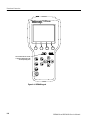
Functional Overview 2--7.......................................
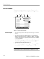
Keypad Controls 2--7.................................................
Side-Panel Connectors and Switches 2--10.................................
Onscreen Readouts 2--12...............................................
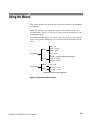
Using the Menus 2--15...........................................
Operating Menus 2--17................................................
Configuration Menu 2--21..............................................
Line Select Menu 2--26................................................
Theory of Operation
Input Board 3--1.....................................................
SDI Interface Board 3--1..............................................
Top Board 3--2......................................................
Bottom Board 3-- 2...................................................
LCD Di splay and Backlight (Serial Numbers B020100 and Above) 3--2........
LCD Display and Backlight (Serial Numbers Below B020100) 3--2............
Performance Verification
Summary Verificatio n 4--2.............................................
Equipment Required 4--3..............................................
Performance Verification: Analog Section 4--5.....................
Sync Separation 4--5.................................................
Sweep Timing and Integral Linearity 4-- 6................................
Vertical Gain and Vertical Magnifier Registration 4-- 7.......................

Table of Contents
ii
WFM90D and WFM91D Service Manual
Variable Gain Range and Vertical Position Range 4-- 7.......................
Overscan 4-- 8.......................................................
Input and DC Restorer Frequency Response 4--9...........................
Vector Phase Stability 4-- 11.............................................
Chrominance Bandwidth 4-- 12..........................................
Audio Gain and Frequency Response 4--13................................
Performance Verification: Digital Section 4--15......................
Check Sync Separation 4--15............................................
Check Frequency Response 4--16........................................
Check Frequency Response at X5 Gain 4--17...............................
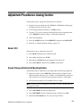
Adjustment Procedures
Adjustments 5--1..............................................
Summary Adjustment 5-- 1.............................................
Equipment Required 5--2..............................................
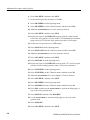
Adjustment Procedures 5--3............................................
Adjustment Procedures: Analog Section 5--5.......................
Raster VCO 5--5.....................................................
Sweep Timing and Horizontal Mag Registration 5-- 5........................
Vertical Gain and X5 Gain Registration 5-- 7...............................
Frequency Response 5--7..............................................
Vector Quadrature Phase 5 --9..........................................
VectorGainandX5GainPhase 5--9.....................................
Audio Gain 5--10.....................................................
Adjustment Procedures: Digital Section 5--11.......................
Vertical Gain 5-- 11....................................................
Frequency Response 5--12..............................................
VectorGainandX5GainPhase 5--12.....................................
Cable Margin 5--13...................................................
Maintenance
Cleaning 6--1.......................................................
After Repair Adjustments 6--2..........................................
Repackaging Instructions 6--2..........................................
Remove and Replace 6--3.......................................
Tools Required 6--3..................................................
Procedures 6--4......................................................
Top Cover Assembly 6 --5.............................................
LCD Display Assembly 6-- 7...........................................
Top Board Assembly 6-- 15.............................................
Battery Cover Assembly 6-- 25...........................................
Batteries 6-- 28.......................................................
Bottom Cover Assembly 6-- 31..........................................
Troubleshooting Procedures 6--39.................................
Equipment Required 6--39..............................................
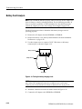
Battery-Fault Analysis 6 -- 40............................................
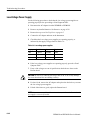
Low-Voltage Power Supply 6--42........................................
Fault Symptom Table 6--43.............................................
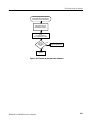
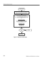
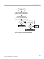
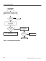
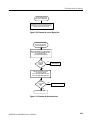
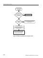
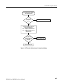
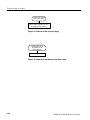
Troubleshooting Flowcharts 6--44........................................

Table of Contents
WFM90D and WFM91D Service Manual
iii
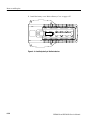
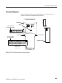
Connector Diagram 6--59..............................................
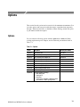
Options
Options 7--1........................................................
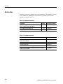
Accessories 7-- 2.....................................................
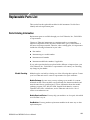
Replaceable Mechanical Parts
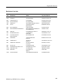
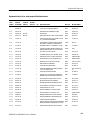
Replaceable Parts List 8--1......................................
Parts Ordering Information 8-- 1.........................................
Using the Replaceable Parts List 8-- 2....................................
Diagrams
Diagrams 9--1.................................................

Table of Contents
iv
WFM90D and WFM91D Service Manual
List of Figures
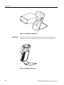
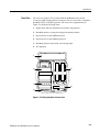
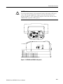
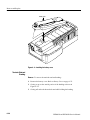
Figure 2--1: Installing the viewing hood 2--2.......................
Figure 2--2: Installing the desk stand 2--2..........................
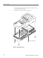
Figure 2--3: Packing the Option 33 travel case 2--3..................
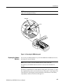
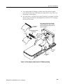
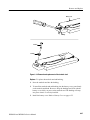
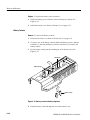
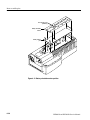
Figure 2--4: Removing the NiMH battery pack 2--5.................
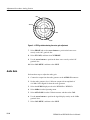
Figure 2--5: Inside of the battery compartment, showing
polarity markings 2--6......................................
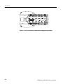
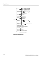
Figure 2--6: WFM90D keypad 2--8...............................
Figure 2--7: WFM90D and WFM91D side p anels 2--11...............
Figure 2--8: Onscreen readout messages 2--12.......................
Figure 2--9: Waveform and Vector menus 2--15......................
Figure 2--10: Audio, Picture, and Waveform-in-Picture menus 2--16....
Figure 2--11: Line Select menu 2--16...............................
Figure 2--12: Configuration menu 2--22............................
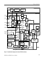
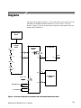
Figure 3--1: Simplified block diagram
(serial numbers B020100 and above) 3--3......................
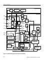
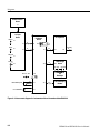
Figure 3--2: Simplified block diagram
(serial numbers below B020100) 3--4..........................
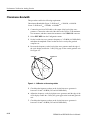
Figure 4--1: --3 dB marks on the vector graticule 4--12................
Figure 5--1: NTSC graticule showing the vector gain adjustment 5--10..
Figure 6--1: Removing the top cover 6--6..........................
Figure 6--2: Removing the cables from the LCD DIsplay assembly 6--9.
Figure 6--3: LCD Display assembly feet 6--10........................
Figure 6--4: Installing the LCD display cable 6--12...................
Figure 6--5: Installing the LCD disp lay 6--13........................
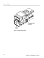
Figure 6--6: Installing the keypad 6--16............................
Figure 6--7: Installing the Top board shield 6--18....................
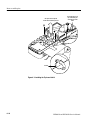
Figure 6--8: Installing the Bottom b oard 6--20.......................
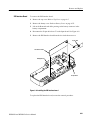
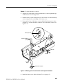
Figure 6--9: Installing the SDI Interface board 6--21..................
Figure 6--10: Removing the B acklight board 6--23...................
Figure 6--11: Installing the battery cover 6--26.......................
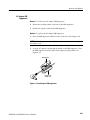
Figure 6--12: Removal and replacement of the turnlock stud 6--27......
Figure 6--13: Removing the NiMH battery pack 6--29................
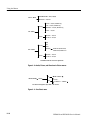
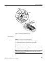
Figure 6--14: Installed polarity of alkaline batteries 6--30.............

Table of Contents
WFM90D and WFM91D Service Manual
v
Figure 6--15: Battery contact installation alignment 6--32.............
Figure 6--16: Battery power-wire and turnlock stud receptacle
installation 6--33............................................
Figure 6--17: Battery orientation marker position 6--36...............
Figure 6--18: Installing the EMI suppressor 6--37....................
Figure 6--19: Testing the battery charging circuit 6--40................
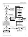
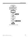
Figure 6--20: Flowchart for no disp lay 6--45........................
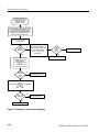
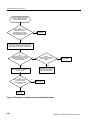
Figure 6--21: Flowchart for distorted waveform d isplay 6--46..........
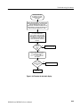
Figure 6--22: Flowchart for no vector disp lay 6--47...................
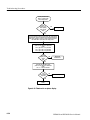
Figure 6--23: Flowchart for problems processing serial digital
input signals 6--48...........................................
Figure 6--24: Flowchart for bad au dio display 6--49..................
Figure 6--25: Flowchart for no picture disp lay 6-- 50..................
Figure 6--26: Flowchart for bad graticules and menus 6--51...........
Figure 6--27: Flowchart for all white display 6--52...................
Figure 6--28: Flowchart for untriggered waveform display 6--53........
Figure 6--29: Flowchart for unlocked vector d isplay 6--54.............
Figure 6--30: Flowchart for vector display jitter 6--55.................
Figure 6--31: Flowchart for distorted vectors 6--55...................
Figure 6--32: Flowchart for problems with the instrument
controls 6--56...............................................
Figure 6--33: Flowchart for bad menus in the picture display 6--57.....
Figure 6--34: Flowchart for dim or blotch y display 6--58..............
Figure 6--35: Flowchart for bad displays except Picture mode 6--58.....
Figure 6--36: Circuit board connector an d pin locations 6--59..........
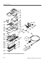
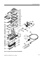
Figure 8--1: Exploded view (serial numbers B020100 and above) 8--4..
Figure 8--2: Exploded view (serial numbers below B020100) 8--7......
Figure 9--1: Interconnect diagram for instruments with
serial numbers B020100 and above 9--1........................
Figure 9--2: Interconnect diagram for instruments with
serial numbers below B020100 9--2............................

Table of Contents
vi
WFM90D and WFM91D Service Manual
List of Tables
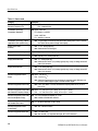
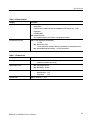
Table 1--1: Vertical deflection system 1--2.........................
Table 1--2: DC restoration 1--4...................................
Table 1--3: Audio mode 1--5.....................................
Table 1--4: Horizontal deflection system 1--5......................
Table 1--5: Vector mode 1--6....................................
Table 1--6: Synchronization 1--7.................................
Table 1--7: Power source 1--7...................................
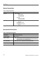
Table 1--8: Physical characteristics 1--8..........................
Table 1--9: Environmental characteristics 1--8.....................
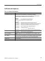
Table 1--10: Certifications and Compliances 1--9...................
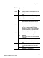
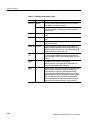
Table 2--1: Video readout messages 2--13...........................
Table 2--2: Waveform menu choices, analog and digital 2--18..........
Table 2--3: Vector menu choices, analog and digital 2--18.............
Table 2--4: Audio menu choices 2--19..............................
Table 2--5: Picture menu choices, analog and digital 2--19............
Table 2--6: WIP menu choices, analog and digital 2--20...............
Table 2--7: Configure menu choices 2--23..........................
Table 2--8: Default instrument settings 2-- 25........................
Table 2--9: Line Select menu choices 2--26..........................
Table 4--1: Summary verification procedure 4--2...................
Table 4--2: Equipment required for performance verification 4--3.....
Table 5--1: Summary adjustment 5--1............................
Table 5--2: Equipment required for adjustments 5--2...............
Table 6--1: Tools req uired for module removal 6-- 3.................
Table 6--2: Remove and replace procedure list 6--4.................
Table 6--3: Equipment required for troubleshooting 6--39............
Table 6--4: Low-voltage power supplies 6--42.......................
Table 6--5: Fault symptom table 6--43.............................
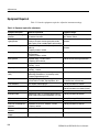
Table 7--1: Options 7--1........................................
Table 7--2: Standard accessories 7--2.............................
Table 7--3: Optional accessories 7--2..............................

WFM90D and WFM91D Service Manual
vii
General Safety Summary
Review the following safety precautions to avoid injury and prevent damage to
this product or any products connected to it.
To avoid potential hazards, use this product only as specified.
Only qualified personnel should perform service procedures.
While using this product, you may need to access other parts of the system. Read
the General Safety Summary in other system manuals for warnings and cautions
related to operating the system.
Connect and Disconnect Properly. Do not connect or disconnect probes or test
leads while they are connected to a voltage source.
Observe All Terminal Rat ings. To avoid fire or shock hazard, observe all ratings
and markings on the product. Consult the product manual for further ratings
information before making connections to the product.
Do not apply a potential to any terminal, including the common terminal, that
exceeds the maximum rating of that terminal.
Replace Batteries Properly. Replace batteries only with the proper type and rating
specified.
Recharge Batteries Proper ly. Recharge batteries for the recommended charge
cycle only.
Use Proper AC Adapter. Use only the AC adapter specified for this product.
Do Not Operate Without Covers. Do not operate this product with covers or panels
removed.
Use Proper Fuse. Use only the fuse type and rating specified for this product.
Avoid Exposed Circuitry. Do not touch exposed connections and components
when power is present.
Do Not Operate With Suspected Failures. If you suspect there is damage to this
product, have it inspected by qualified service personnel.
Do Not Operate in Wet/Damp Conditions.
Do Not Operate in an Explosive Atmosphere.
Keep Product Surfaces Clean and Dry.

General Safety Summary
viii
WFM90D and WFM91D Service Manual
Term s in this Manual. These terms may appear in this manual:
WARNING. Warning statements identify conditions or practices that could result
in injury or loss of life.
CAUTION. Caution statements identify conditions or practices that could result in
damage to this product or other property.
Terms on the Product. These terms may appear on the product:
DANGER indicates an injury hazard immediately accessible as you read the
marking.
WARNING indicates an injury hazard not immediately accessible as you read the
marking.
CAUTION indicates a hazard to property including the product.
Symbols on the Product. The following symbols may appear on the product:
CAUTION
Refer to Manual
Symbols and Terms

WFM90D and WFM91D Service Manual
ix
Service Safety Summary
Only qualified personnel should perform service procedures. Read this Service
Safety Summary and the General Safety Summary before performing any service
procedures.
Do Not Service Alone. Do not perform internal service or adjustments of this
product unless another person capable of rendering first aid and resuscitation is
present.
Disconnect Power. To avoid electric shock, switch off the instrument power, then
disconnect the power cord from the mains power.
Use Care When Servicing With Power On. Dangerous voltages or currents may
exist in this product. Disconnect power, remove battery (if applicable), and
disconnect test leads before removing protective panels, soldering, or replacing
components.
To avoid electric shock, do not touch exposed connections.

Service Safety Summary
x
WFM90D and WFM91D Service Manual

WFM90D and WFM91D Service Manual
xi
Preface
This manual provides instructions for servicing the WFM90D and WFM91D
Handheld Waveform, Vector, Picture, and Audio Monitors. This manual
describes features and specifications that are common to all generator modules.
These include system configuration and the common control interface.
About This Manual
This manual is composed of the following sections:
H Specifications lists the electrical and environmental specifications and
provides a general product description.
H Operating Information describes installation and front panel operation of the
instrument.
H Theory of Operation contains a module-level description based on block
diagrams of the instrument circuitry.
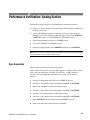
H Performance Verification provides procedures for verifying instrument
performance.
H Adjustment Procedures provides procedures for adjusting the instrument to
meet performance levels listed in Specifications.
H Maintenance contains instructions for cleaning the instrument, procedures
for removal and replacement of instrument modules, and troubleshooting
procedures.
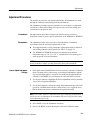
H Options lists all of the options that you might find on your instrument.
H Replaceable Mechanical Parts lists the part numbers of the replaceable
electrical and mechanical parts and assemblies.
H Diagrams contains the instrument interconnect diagram.
Related Manuals
The WFM90D & WFM91D Handheld Waveform, Vector, Picture, & Audio
Monitor User Manual (Tektronix part number 071-1142-XX) describes in detail
how to operate the instrument.

Preface
xii
WFM90D and WFM91D Service Manual
Contacting Tektronix
Phone 1-800-833-9200*
Address Tektronix, Inc.
Department or name (if known)
14200 SW Karl Braun Drive
P.O. Box 500
Beaverton, OR 97077
USA
Web site www.tektronix.com
Sales support 1-800-833-9200, select option 1*
Service support 1-800-833-9200, select option 2*
Technical support www.tektronix.com/support
1-800-833-9200, select option 3*
6:00 a.m. -- 5:00 p.m. Pacific Standard Time
* This phone number is toll free in North America. After office hours, please leave a voice mail
message.
Outside North America, contact a Tektronix sales office or distributor; see the Tektronix web
site for a list of offices.

Specifications


WFM90D and WFM91D Service Manual
1-1
Specifications
This section includes the following information:
H Product description
H Specifications tables
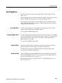
Product Description
The handheld, self-contained, Tektronix WFM90D and WFM91D television
waveform monitors can monitor analog and digital signals. The monitors provide
composite and component waveform displays as well as vector and picture
displays.
These monitors can be used in the traditional in-house applications of television
production, post-production, and signal transmission. In addition, their portabili-
ty allows them to be used in non-traditional applications such as field production
and system maintenance.
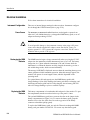
H Accepts NTSC/PAL composite video or 525/625 Component 270 Mbit serial
digital video signals
H Automatic detection of analog or serial digital signals
H Built-in color display (TFT LC D)
H Viewing angle control
H Electronic graticules
H Battery or AC adapter powered
H Menu-assisted monitoring operation
H Audio signal input/output
H Waveform, Vector, Picture, Audio, and Waveform-in-Picture display modes
H Line select lets you view any single line of video
H Selectable time out for backlight or instrument power
H Signal level alarm mode for waveform and audio displays
H Preset menu to store/recall front panel and menu setups
H Instrument adjustments from front panel (see service manual)
Key Features

Specifications
1-2
WFM90D and WFM91D Service Manual
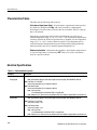
Characteristics Tables
The tables use the following abbreviations:
Performance Requirement (Req). All performance requirements in the specifica-
tion tables are identified with Req, and can be assured by completing the
Performance Check Procedure located in the service manual. Allow a warm-up
time of 20 minutes.
Performance requirements in the electrical specifications are valid over an
ambient temperature range of +20° Cto+30° C. The Performance Requirement
tolerances listed in the Electrical Specification are doubled over the temperature
range of 0° Cto+40° C, unless otherwise specified. Test equipment used to
verify Performance Requirements must be calibrated and working within the
limits specified in the service manual Equipment Required List.
Reference Information. Information that amplifies a performance requirement or
is of special importance is indicated by REF. There is no need to check these
items to a specific tolerance.
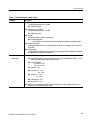
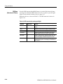
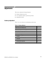
Electrical Specifications
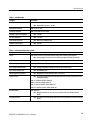
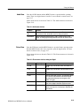
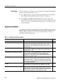
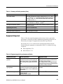
Table 1- 1: Vertical deflection system
Category Description
Frequency Response
Analog Input REF: Specifications apply for full screen height video input signal, with VARIABLE GAIN off.
REQ: Flat Filter 1 V Full Scale:
50 kHz to 6 MHz within 2% of response at 50 kHz.
REQ: Flat Filter X5 Gain:
50 kHz to 6 MHz within 5% of response at 50 kHz.
REF: Low Pass Filter:
≥40 dB attenuation at 3.58 MHz NTSC, 4.43 MHz PAL.
REF: Response at 15 kHz does not vary between FLAT and LUM (low pass) filters by more than 1%.
Digital Input REF: Specifications apply for full screen height video input signal, with VARIABLE GAIN off.
REQ: Flat Filter 1 V Full Scale:
50 kHz to 4.5 MHz ±4%.
REQ: Flat Filter X5 Gain:
50 kHz to 4.5 MHz ±5%.
REF: Low Pass Filter:
≥40 dB attenuation at 3.58 MHz NTSC, 4.43 MHz PAL.
REF: Response at 15 kHz does not vary between FLAT and LUM (low pass) filters by more than 1%.
Page is loading ...
Page is loading ...
Page is loading ...
Page is loading ...
Page is loading ...
Page is loading ...
Page is loading ...
Page is loading ...
Page is loading ...
Page is loading ...
Page is loading ...
Page is loading ...
Page is loading ...
Page is loading ...
Page is loading ...
Page is loading ...
Page is loading ...
Page is loading ...
Page is loading ...
Page is loading ...
Page is loading ...
Page is loading ...
Page is loading ...
Page is loading ...
Page is loading ...
Page is loading ...
Page is loading ...
Page is loading ...
Page is loading ...
Page is loading ...
Page is loading ...
Page is loading ...
Page is loading ...
Page is loading ...
Page is loading ...
Page is loading ...
Page is loading ...
Page is loading ...
Page is loading ...
Page is loading ...
Page is loading ...
Page is loading ...
Page is loading ...
Page is loading ...
Page is loading ...
Page is loading ...
Page is loading ...
Page is loading ...
Page is loading ...
Page is loading ...
Page is loading ...
Page is loading ...
Page is loading ...
Page is loading ...
Page is loading ...
Page is loading ...
Page is loading ...
Page is loading ...
Page is loading ...
Page is loading ...
Page is loading ...
Page is loading ...
Page is loading ...
Page is loading ...
Page is loading ...
Page is loading ...
Page is loading ...
Page is loading ...
Page is loading ...
Page is loading ...
Page is loading ...
Page is loading ...
Page is loading ...
Page is loading ...
Page is loading ...
Page is loading ...
Page is loading ...
Page is loading ...
Page is loading ...
Page is loading ...
Page is loading ...
Page is loading ...
Page is loading ...
Page is loading ...
Page is loading ...
Page is loading ...
Page is loading ...
Page is loading ...
Page is loading ...
Page is loading ...
Page is loading ...
Page is loading ...
Page is loading ...
Page is loading ...
Page is loading ...
Page is loading ...
Page is loading ...
Page is loading ...
Page is loading ...
Page is loading ...
Page is loading ...
Page is loading ...
Page is loading ...
Page is loading ...
Page is loading ...
Page is loading ...
Page is loading ...
Page is loading ...
Page is loading ...
Page is loading ...
Page is loading ...
Page is loading ...
Page is loading ...
Page is loading ...
Page is loading ...
Page is loading ...
Page is loading ...
Page is loading ...
Page is loading ...
Page is loading ...
Page is loading ...
Page is loading ...
Page is loading ...
Page is loading ...
Page is loading ...
Page is loading ...
Page is loading ...
Page is loading ...
Page is loading ...
Page is loading ...
Page is loading ...
Page is loading ...
Page is loading ...
Page is loading ...
Page is loading ...
Page is loading ...
Page is loading ...
Page is loading ...
Page is loading ...
Page is loading ...
Page is loading ...
Page is loading ...
Page is loading ...
Page is loading ...
Page is loading ...
Page is loading ...
Page is loading ...
Page is loading ...
Page is loading ...
Page is loading ...
Page is loading ...
Page is loading ...
Page is loading ...
Page is loading ...
Page is loading ...
Page is loading ...
Page is loading ...
Page is loading ...
Page is loading ...
Page is loading ...
-
 1
1
-
 2
2
-
 3
3
-
 4
4
-
 5
5
-
 6
6
-
 7
7
-
 8
8
-
 9
9
-
 10
10
-
 11
11
-
 12
12
-
 13
13
-
 14
14
-
 15
15
-
 16
16
-
 17
17
-
 18
18
-
 19
19
-
 20
20
-
 21
21
-
 22
22
-
 23
23
-
 24
24
-
 25
25
-
 26
26
-
 27
27
-
 28
28
-
 29
29
-
 30
30
-
 31
31
-
 32
32
-
 33
33
-
 34
34
-
 35
35
-
 36
36
-
 37
37
-
 38
38
-
 39
39
-
 40
40
-
 41
41
-
 42
42
-
 43
43
-
 44
44
-
 45
45
-
 46
46
-
 47
47
-
 48
48
-
 49
49
-
 50
50
-
 51
51
-
 52
52
-
 53
53
-
 54
54
-
 55
55
-
 56
56
-
 57
57
-
 58
58
-
 59
59
-
 60
60
-
 61
61
-
 62
62
-
 63
63
-
 64
64
-
 65
65
-
 66
66
-
 67
67
-
 68
68
-
 69
69
-
 70
70
-
 71
71
-
 72
72
-
 73
73
-
 74
74
-
 75
75
-
 76
76
-
 77
77
-
 78
78
-
 79
79
-
 80
80
-
 81
81
-
 82
82
-
 83
83
-
 84
84
-
 85
85
-
 86
86
-
 87
87
-
 88
88
-
 89
89
-
 90
90
-
 91
91
-
 92
92
-
 93
93
-
 94
94
-
 95
95
-
 96
96
-
 97
97
-
 98
98
-
 99
99
-
 100
100
-
 101
101
-
 102
102
-
 103
103
-
 104
104
-
 105
105
-
 106
106
-
 107
107
-
 108
108
-
 109
109
-
 110
110
-
 111
111
-
 112
112
-
 113
113
-
 114
114
-
 115
115
-
 116
116
-
 117
117
-
 118
118
-
 119
119
-
 120
120
-
 121
121
-
 122
122
-
 123
123
-
 124
124
-
 125
125
-
 126
126
-
 127
127
-
 128
128
-
 129
129
-
 130
130
-
 131
131
-
 132
132
-
 133
133
-
 134
134
-
 135
135
-
 136
136
-
 137
137
-
 138
138
-
 139
139
-
 140
140
-
 141
141
-
 142
142
-
 143
143
-
 144
144
-
 145
145
-
 146
146
-
 147
147
-
 148
148
-
 149
149
-
 150
150
-
 151
151
-
 152
152
-
 153
153
-
 154
154
-
 155
155
-
 156
156
-
 157
157
-
 158
158
-
 159
159
-
 160
160
-
 161
161
-
 162
162
-
 163
163
-
 164
164
-
 165
165
-
 166
166
-
 167
167
-
 168
168
-
 169
169
-
 170
170
-
 171
171
-
 172
172
-
 173
173
-
 174
174
-
 175
175
-
 176
176
-
 177
177
-
 178
178
-
 179
179
-
 180
180


Tektronix 071-1143-01 User manual
- Type
- User manual
- This manual is also suitable for
Ask a question and I''ll find the answer in the document
Finding information in a document is now easier with AI
Related papers
-
Tektronix WFM91D User manual
-
-
-
-
-
-
-
-
-
Other documents
-
SCANGRIP MAG PRO Multipurpose and Rechargeable LED Work Light User guide
-
BenQ BL2420PT Professional and Photography Monitor User manual
-
SRS SR2124 Owner's manual
-
Spin Master Regenerator User manual
-
-
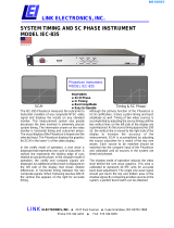 Link electronic IEC-835 User manual
-
Panasonic WVCM2000 Operating instructions
-
Hamlet Adept A700WVA Owner's manual
-
Fluke PM5414V User manual
-
BST WP-160 Owner's manual
