Agilent Technologies E3630A User manual
- Category
- Power supply units
- Type
- User manual

DUAL OUTPUT POWER SUPPLY
Agilent MODEL E3630A
OPERATING AND SERVICE MANUAL
FOR INSTRUMENTS WITH SERIAL NUMBERS
KR85014528 AND ABOVE
For instruments with Serial Numbers above
KR85014528, a change page may be included.
Manual Part No. 5959-5329
I
April 2000
Edition 7

1-2
SAFETY SUMMARY
The following general safety precautions must be observed during all phases of operation, service, and repair of this instrument.
Failure to comply with these precautions or with specific warnings elsewhere in this manual violates safety standards of design,
manufacture, and intended use of the instrument. Agilent Technologies assumes no liability for the customer's failure to comply
with these requirements.
BEFORE APPLYING POWER.
Verify that the product is set to match the available line volt-
age and that the correct fuse is installed.
GROUND THE INSTRUMENT.
This product is a Safety Class I instrument (provided with a
protective earth terminal). To minimize shock hazard, the
instrument chassis and cabinet must be connected to an
electrical ground. The instrument must be connected to the
ac power supply mains through a three-conductor power
cable, with the third wire firmly connected to an electrical
ground(safety ground) at the power outlet. Any interruption of
the protective(grounding) conductor or disconnection of the
protective earth terminal will cause a potential shock hazard
that could result in personal injury. If the instrument is to be
energized via an external autotransformer for voltage reduc-
tion, be certain that the autotransformer common terminal is
connected to the neutral(earthed pole) of the ac power lines
(supply mains).
DO NOT OPERATE IN AN EXPLOSIVE ATMOSPHERE.
Do not operate the instrument in the presence of flammable
gases or fumes.
KEEP AWAY FROM LIVE CIRCUITS.
Operating personnel must not remove instrument covers.
Component replacement and internal adjustments must be
made by qualified service personnel. Do not replace compo-
nents with power cable connected. Under certain conditions,
dangerous voltages may exist even with the power cable
removed. To avoid injuries, always disconnect power, dis-
charge circuits and remove external voltage sources before
touching components.
DO NOT SERVICE OR ADJUST ALONE.
Do not attempt internal service or adjustment unless another
person, capable of rendering first aid and resuscitation, is
present.
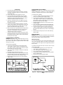
SAFETY SYMBOLS
Instruction manual symbol; the product
will be marked with this symbol when it is
necessary for the user to refer to the
instruction manual.
Indicate earth(ground) terminal.
The WARNING sign denotes a hazard. It
calls attention to a procedure, practice,
or the like, which, if not correctly per-
formed or adhered to, could result inper-
sonal injury. Do not proceed beyond a
WARNING sign until the indicated con-
ditions are fully understood and met.
The CAUTION sign denotes a hazard. It
calls attention to an operating procedure,
or the like, which, if not correctly per-
formed or adhered to, could result in
damage to or destruction of part or all of
the product. Do not proceed beyond
CAUTION sign until the indicated condi-
tions are fully understood and met.
The NOTE sign denotes important infor-
mation. It calls attention to a procedure,
practice, condition or the like, which is
essential to highlight.
DO NOT SUBSTITUTE PARTS OR MODIFY INSTRUMENT.
Because of the danger of introducing additional hazards, do
not install substitute parts or perform any unauthorized modi-
fication to the instrument. Return the instrument to a Agilent
Technologies Sales and Service Office for service and repair
to ensure that safety features are maintained.
Instruments that appear damaged or defective should be made inoperative and secured against unintended
operation until they can be repaired by qualified service personnel.
!
or
CAUTION
WARNING
NOTE

1-3
Table of Contents
SAFETY SUMMARY . . . . . . . . . . . . . . . . . . . . . . . . . . . . . . . . . . . . . . . . . . . . . . . . . . . . . . . . . . . . . . 1-2
GENERAL INFORMATION . . . . . . . . . . . . . . . . . . . . . . . . . . . . . . . . . . . . . . . . . . . . . . . . . . . . . . . . . 1-4
INTRODUCTION. . . . . . . . . . . . . . . . . . . . . . . . . . . . . . . . . . . . . . . . . . . . . . . . . . . . . . . . . . . . . . . . 1-4
SAFETY CONSIDERATIONS . . . . . . . . . . . . . . . . . . . . . . . . . . . . . . . . . . . . . . . . . . . . . . . . . . . . . . 1-4
SAFETY AND EMC REQUIREMENTS. . . . . . . . . . . . . . . . . . . . . . . . . . . . . . . . . . . . . . . . . . . . . . . 1-4
INSTRUMENT AND MANUAL IDENTIFICATION. . . . . . . . . . . . . . . . . . . . . . . . . . . . . . . . . . . . . . . 1-4
OPTIONS . . . . . . . . . . . . . . . . . . . . . . . . . . . . . . . . . . . . . . . . . . . . . . . . . . . . . . . . . . . . . . . . . . . . . 1-4
ACCESSORY . . . . . . . . . . . . . . . . . . . . . . . . . . . . . . . . . . . . . . . . . . . . . . . . . . . . . . . . . . . . . . . . . . 1-4
DESCRIPTION . . . . . . . . . . . . . . . . . . . . . . . . . . . . . . . . . . . . . . . . . . . . . . . . . . . . . . . . . . . . . . . . . 1-4
LINE FUSE . . . . . . . . . . . . . . . . . . . . . . . . . . . . . . . . . . . . . . . . . . . . . . . . . . . . . . . . . . . . . . . . . . . . 1-5
SPECIFICATIONS . . . . . . . . . . . . . . . . . . . . . . . . . . . . . . . . . . . . . . . . . . . . . . . . . . . . . . . . . . . . . . 1-5
INSTALLATION. . . . . . . . . . . . . . . . . . . . . . . . . . . . . . . . . . . . . . . . . . . . . . . . . . . . . . . . . . . . . . . . . . 1-6
INITIAL INSPECTION . . . . . . . . . . . . . . . . . . . . . . . . . . . . . . . . . . . . . . . . . . . . . . . . . . . . . . . . . . . . 1-6
Mechanical Check . . . . . . . . . . . . . . . . . . . . . . . . . . . . . . . . . . . . . . . . . . . . . . . . . . . . . . . . . 1-6
Electrical Check . . . . . . . . . . . . . . . . . . . . . . . . . . . . . . . . . . . . . . . . . . . . . . . . . . . . . . . . . . . 1-6
INSTALLATION DATA . . . . . . . . . . . . . . . . . . . . . . . . . . . . . . . . . . . . . . . . . . . . . . . . . . . . . . . . . . . 1-6
Location and Cooling . . . . . . . . . . . . . . . . . . . . . . . . . . . . . . . . . . . . . . . . . . . . . . . . . . . . . . . 1-6
Outline Diagram . . . . . . . . . . . . . . . . . . . . . . . . . . . . . . . . . . . . . . . . . . . . . . . . . . . . . . . . . . . 1-6
Rack Mounting . . . . . . . . . . . . . . . . . . . . . . . . . . . . . . . . . . . . . . . . . . . . . . . . . . . . . . . . . . . . 1-6
INPUT POWER REQUIREMENTS. . . . . . . . . . . . . . . . . . . . . . . . . . . . . . . . . . . . . . . . . . . . . . . . . . 1-6
Power Cable. . . . . . . . . . . . . . . . . . . . . . . . . . . . . . . . . . . . . . . . . . . . . . . . . . . . . . . . . . . . . . 1-6
OPERATING INSTRUCTIONS . . . . . . . . . . . . . . . . . . . . . . . . . . . . . . . . . . . . . . . . . . . . . . . . . . . . . . 1-6
INTRODUCTION. . . . . . . . . . . . . . . . . . . . . . . . . . . . . . . . . . . . . . . . . . . . . . . . . . . . . . . . . . . . . . . . 1-6
TURN -ON CHECKOUT PROCEDURE . . . . . . . . . . . . . . . . . . . . . . . . . . . . . . . . . . . . . . . . . . . . . . 1-7
OPERATION . . . . . . . . . . . . . . . . . . . . . . . . . . . . . . . . . . . . . . . . . . . . . . . . . . . . . . . . . . . . . . . . . . . 1-7
Tracking Ratio Control . . . . . . . . . . . . . . . . . . . . . . . . . . . . . . . . . . . . . . . . . . . . . . . . . . . . . . 1-7
Overload Protection Circuits. . . . . . . . . . . . . . . . . . . . . . . . . . . . . . . . . . . . . . . . . . . . . . . . . . 1-7
Operation Beyond Rated Output . . . . . . . . . . . . . . . . . . . . . . . . . . . . . . . . . . . . . . . . . . . . . . 1-7
Connecting Load . . . . . . . . . . . . . . . . . . . . . . . . . . . . . . . . . . . . . . . . . . . . . . . . . . . . . . . . . . 1-8
Parallel Operation. . . . . . . . . . . . . . . . . . . . . . . . . . . . . . . . . . . . . . . . . . . . . . . . . . . . . . . . . . 1-8
Series Operation. . . . . . . . . . . . . . . . . . . . . . . . . . . . . . . . . . . . . . . . . . . . . . . . . . . . . . . . . . . 1-8
LOAD CONSIDERATIONS . . . . . . . . . . . . . . . . . . . . . . . . . . . . . . . . . . . . . . . . . . . . . . . . . . . . . . . . . 1-8
PULSE LOADING . . . . . . . . . . . . . . . . . . . . . . . . . . . . . . . . . . . . . . . . . . . . . . . . . . . . . . . . . . . . . . . 1-8
REVERSE CURRENT LOADING . . . . . . . . . . . . . . . . . . . . . . . . . . . . . . . . . . . . . . . . . . . . . . . . . . . 1-8
OUTPUT CAPACITANCE. . . . . . . . . . . . . . . . . . . . . . . . . . . . . . . . . . . . . . . . . . . . . . . . . . . . . . . . . 1-8
REVERSE VOLTAGE PROTECTION . . . . . . . . . . . . . . . . . . . . . . . . . . . . . . . . . . . . . . . . . . . . . . . 1-8

1-4
GENERAL INFORMATION
INTRODUCTION
This section contains general information concerning the
E3630A triple output power supply. Included are safety con-
siderations, safety and EMC requirements, instrument and
manual identification, option and accessory information,
instrument description, and specifications.
SAFETY CONSIDERATIONS
This product is a Safety Class I instrument, which means that
it is provided with a protective earth ground terminal. This ter-
minal must be connected to an ac source that has a 3-wire
ground receptacle. Review the instrument rear panel and this
manual for safety markings and instructions before operating
the instrument. Refer to the Safety Summary page at the
beginning of this manual for a summary of general safety
information. Specific safety information is located at the
appropriate places in this manual.
SAFETY AND EMC REQUIREMENTS
This power supply is designed to comply with the following
safety and EMC(Electromagnetic Compatibility) require-
ments:
n IEC 1010-1(1990)/EN 61010 (1993): Safety Require-
ments for Electrical Equipment for Measurement, Control,
and Laboratory Use
n CSA C22.2 No.231: Safety Requirements for Electrical
and Electronic Measuring and Test Equipment
n UL 1244: Electrical and Electronic Measuring and Testing
Equipment
n EMC Directive 89/336/EEC: Council Directive entitled
Approximation of the Laws of the Member States relating
to Electromagnetic Compatibility
n EN 55011(1991) Group 1, Class B/CISPR 11 (1990): Lim-
its and Methods of Radio Interference Characteristics of
Industrial, Scientific, and Medical(ISM) Radio - Fre-
quency Equipment
n EN 50082-1(1992) /
IEC 801-2(1991): Electrostatic Discharge Require-
ments
IEC 801-3(1984): Radiated Electromagnetic Field
Requirements
IEC 801-4(1988): Electrical Fast Transient/Burst
Requirements
INSTRUMENT AND MANUAL IDENTIFICATION
A serial number identifies your power supply. The serial num-
ber encodes the country of manufacture, the week of the lat-
est significant design change, and a unique sequential
number. The letter "KR" designates Korea as the country of
manufacture, the first one digit indicates the year (3=1993,
4=1994, and so forth), and the second two digits indicate the
week. The remaining digits of the serial number are a unique,
five-digit number assigned sequentially.
If the serial number on your supply does not agree with those
on the title page of the manual, a yellow Change Sheet is
supplied with the manual to explain the difference
between your instrument and the instrument described by this
manual. The Change Sheet may also contain information for
correcting errors in the manual.
OPTIONS
Options OE3 and OE9 determine which line voltage is
selected at the factory. The standard unit is configured for 115
Vac ± 10%, 47-63 Hz input.
Option No. Description
OE3: 230 Vac ± 10%, 47-63 Hz Input
OE9: 100 Vac ± 10%, 47-63 Hz Input
910: One additional operating and service manual
shipped with the power supply
ACCESSORY
The accessory listed below may be ordered from your local
Agilent Technologies Sales Office either with the power sup-
ply or separately. (Refer to the list at the rear of the manual for
address.)
Agilent Part No.Description
5063-9767 Rack Kit for mounting one or two 3 1/2" high
supplies in a standard 19" rack
The rack mount kit is needed for rack mounting of the
E3630A power supply.
DESCRIPTION
This constant-voltage/current-limiting triple output power sup-
ply combines two 0 to ±20V tracking outputs rated at 0.5
amps with an additional single output that is rated at 0 to 6
volts and 2.5 amps. The +20V and -20V tracking outputs can
also be used in series as a single 0 to 40V 0.5-amp output.
Connections to the supply's output and to chassis ground are
made to binding posts on the front panel. The supply's three
outputs share a common output terminal, which is isolated
from chassis ground so that any one output terminal can be
grounded.
All outputs are protected against overload and short-circuit
damage. The ±20V outputs are protected by circuits that limit
the output current to 110% of its nominal maximum. The over-
load protection circuit for the +6V output has a current fold-
back characteristic that reduces the output current as an
overload increases until only 1 amp flows through a short cir-
cuit. The 6V output current limit depends on the output termi-
nal voltage and varies linearly between 2.75 amps at 6 volts
and 1 amp at zero volts.
All controls, digital meter, and output terminals are located on the
front panel. One voltage control sets the 0 to 6V and another
sets the voltages of the 0 to +20V and 0 to -20V outputs simul-
taneously. These dual tracking outputs are made more versatile
by providing a tracking ratio control in addition to the usual volt-
age control. With the tracking ratio control turned fully clockwise
to its "fixed" position, the dual outputs have a fixed 1:1 tracking
ratio. As the ±20V voltage control is adjusted, the voltage of the
negative supply tracks the positive output within ±1%. Turning
the tracking ratio control away from its fully clockwise position
switches the dual tracking outputs into a variable tracking ratio

1-5
mode. In this mode the voltage of the negative output can be set
lower than that of the positive output. The tracking ratio control
allows the negative supply's output to be set to any value
between a maximum that is within ±5% of the positive supply's
output and a minimum that is less than 0.5 volts. Once a ratio is
established by the tracking ratio control, the ratio of the positive
output voltage to the negative output voltage remains constant
as the ±20V voltage control varies the 0 to +20V output over its
range.
The front panel also contains a line switch, three overload
indicators for +6V output, +20V output, and -20V output, a
voltmeter and an ammeter, and three push-button meter
switches. The push buttons select one of the supply's three
outputs for display. The voltmeter and ammeter always moni-
tor any one supply simultaneously. In addition to the standard
115 Vac ± 10% 47 to 63 Hz input, two other line voltage options
are available for nominal inputs of 100 and 230 Vac. The sup-
ply is furnished with a detachable 3-wire grounding type line
cord. The ac line fuse is in an extractor type fuseholder on the
rear heat sink.
LINE FUSE
The line fuse is located by the ac line receptacle. Check the
rating of the line fuse and replace it with the correct fuse if
necessary as indicated below. These are slow-blow fuses.
Line Voltage Fuse Agilent Part No.
100/115 Vac 1.6 A 2110-0918
230 Vac 1.0 A 2110-0599
SPECIFICATIONS
Table 1 lists detailed specifications for the power supply.
Table 1. Specifications
AC INPUT
Standard: 115 Vac ± 10%, 47-63 Hz, 115 VA, 84 W
OE9:
100 Vac ± 10%, 47-63 Hz, 115 VA, 84 W
OE3:
230 Vac ± 10%, 47-63 Hz, 115 VA, 84 W
DC OUTPUT and OVERLOAD PROTECTION
0 to ±20 V Outputs: Maximum rated output current is 0.5 A.
Short circuit output current is 0.55 A ± 5% and a fixed cur-
rent limit circuit limits the output of each supply to this maxi-
mum at any output voltage setting. Unbalanced loads within
current rating are permitted.
0 to +6 V Output:
Maximum rated output current is 2.5 A at
6 V. The maximum available output current decreases with
the output voltage setting. A current foldback circuit limits
the output to 2.75 A ± 5% at 6 volts and, with decreasing
voltage, reduces the current limit linearly to 1 A ± 15% at
zero volts (short circuited).
TRACKING ACCURACY
The +20 V and -20 V outputs track within 1% with the
TRACKING ratio control in the Fixed position. (In variable
tracking ratio mode, the negative tracking output can be
adjusted from less than 0.5 V to within ±5% of the setting of
the positive output.)
LOAD REGULATION
All Outputs: Less than 0.01% plus 2 mV for a full load to
no load change in output current.
LINE REGULATION
All Outputs: Less than 0.01% plus 2 mV for any line volt-
age change within rating.
PARD (Ripple and Noise)
All Outputs: Less than 0.35 mV rms/1.5 mV p-p (20 Hz-20
MHz).
Common Mode Current (CMI):
Less than 1 mA for all
outputs (20 Hz-20 MHz).
OPERATING TEMPERATURE RANGE
0 to 40
o
C for full rated output. At higher temperatures, out-
put current is derated linearly to 50% at 55
o
C maximum
temperature.
TEMPERATURE COEFFICIENT
All Outputs: Less than 0.02% plus 1 mV voltage change
per
o
C over the operating range from 0 to 40
o
C
after 30 minutes warm-up.
STABILITY (OUTPUT DRIFT)
All Outputs: Less than 0.1% plus 5 mV (dc to 20 Hz) dur-
ing 8 hours at constant line, load and ambient
after an initial warm-up time of 30 minutes.
LOAD TRANSIENT RESPONSE TIME
All Outputs: Less than 50 msec for output recovery to
within 15 mV of nominal output voltage
following a load change from full load to half
load, or vice versa.
OUTPUT VOLTAGE OVERSHOOT
All Outputs: During turn-on or turn-off of ac power, output
plus overshoot will not exceed 1 V if the out-
put control is set for less than 1 V. If the con-
trol is set for 1 V or higher, there is no
overshoot.
METER ACCURACY: ±(0.5% of output + 2 counts) at
25
o
C±5
o
C
METER RESOLUTION
All Output: Voltage 10 mV Current 10 mA
DIMENSIONS
212.3 mmW x 88.1 mmH x 269.2 mmD
(8.354 inW x 3.469 inH x 10.591 inD)
WEIGHT: 3.8 kg(8.4 lbs) net, 5.1 kg(11.3 lbs) shipping

1-6
INSTALLATION
INITIAL INSPECTION
Before shipment, this instrument was inspected and found to
be free of mechanical and electrical defects. As soon as the
instrument is unpacked, inspect for any damage that may
have occurred in transit. Save all packing materials until the
inspection is completed. If damage is found, a claim should
be filed with the carrier. The Agilent Technologies Sales and
Service office should be notified as soon as possible.
Mechanical Check
This check should confirm that there are no broken knobs or
connectors, that the cabinet and panel surfaces are free of
dents and scratches, and that the meter is not scratched or
cracked.
Electrical Check
Perform the TURN-ON CHECKOUT PROCEDURE in the fol-
lowing paragraph to confirm that the supply is operational.
Alternately, check the supply more fully using the PERFOR-
MANCE TEST in the service information section.
INSTALLATION DATA
The instrument is shipped ready for bench operation. Before
applying power to the supply, please read the INPUT
POWER REQUIREMENTS paragraph.
Location and Cooling
This instrument is air cooled. Sufficient space should be
allowed so that a free flow of cooling air can reach the sides
and rear of the instrument when it is in operation. It should be
used in an area where the ambient temperature does not
exceed 40
o
C.
Outline Diagram
Figure 1 illustrates the outline shape and dimensions of the
supply.
Rack Mounting
This supply may be rack mounted in a standard 19-inch rack
panel either by itself or alongside a similar unit. Please see
the ACCESSORY, page 1-4, for available rack mounting
accessory. The rack-mounting kit includes complete installa-
tion instructions.
INPUT POWER REQUIREMENTS
Depending on the line voltage option ordered, the supply is
ready to be operated from one of the power sources listed in
Table 1. A label on the rear heat sink shows the nominal input
voltage set for the supply at the factory.
Power Cable
To protect operating personnel, the supply should be
grounded. This supply is equipped with a three conductor
power cable. The third conductor is the ground conductor and
when the cable is plugged into an appropriate receptacle, the
supply is grounded.
The power supply is equipped at the factory with a power
cord plug appropriate for the user's location. Notify the near-
est Agilent Sales and Service Office if the appropriate power
cord is not included with the supply.
Figure 1. Outline Diagram
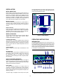
OPERATING INSTRUCTIONS
INTRODUCTION
The following steps describe the use of the front panel con-
trols and indicators illustrated in Figure 2 and serve as a brief
check that the supply is operational. Follow this checkout pro-
cedure or the more detailed performance test of service infor-
mation section when the instrument is received and before it
is connected to any load equipment.
Figure 2. Front-Panel Controls and Indicators

1-7
Before applying power to the supply, check the label on the
heat sink to make certain that the supply's line voltage option
agrees with the line voltage to be used. If the option does not
correspond to your line voltage, refer to paragraph "LINE
VOLTAGE OPTION CONVERSION" in the service section
before applying power.
TURN -ON CHECKOUT PROCEDURE
a. Connect line cord to power source and turn LINE
switch on.
b. Push +6V METER switch and, with no load con-
nected, vary +6V VOLTAGE control over its range
and check that the voltmeter responds to the control
setting and the ammeter indicates zero.
c. Set the +6V VOLTAGE control to 6 volts and short the
+6V output terminal to COM (common) terminal
with an insulated test lead. The ammeter should
indicate a short-circuit output current of approximately
1.0 A. Remove the short from the output terminals.
d. Push the +20V METER switch and turn Tracking
Ratio control fully clockwise to the Fixed position.
With no load connected, vary ±20V VOLTAGE control
over its range and check that the voltmeter
responds to the control setting and the ammeter indi-
cates zero.
e. Set the ±20V VOLTAGE control to 20 volts and
short the +20V output terminal to the COM terminal
with an insulated test lead. The ammeter should
indicate a short-circuit output current of 0.55 A ± 5%.
Remove the short from the output terminals.
f. Repeat steps (d) and (e) for -20 V output.
g. Adjust the +20V output to 20 volts. Then push -20V
METER switch and check the effect of the Tracking
Ratio control on the voltage of the -20V output. The -
20V output should be adjustable from less than 0.5
volts to a maximum of 19 to 21 volts.
If this brief checkout procedure or later use of the supply
reveals a possible malfunction, see the service information
section for detailed test, troubleshooting, and adjustment pro-
cedures.
OPERATION
This power supply can be operated individually or in parallel
or series with another supply (see Parallel and Series Opera-
tion paragraphs). All output terminals are isolated from
ground. The ±20V and +6V outputs use a single common out-
put terminal. This common (COM) terminal or any one of the
other output terminals may be grounded to the chassis at the
front panel ground terminal ( in Figure 2), or all outputs may
be left floating. Loads can be connected separately between
each of the 0 to ±20V output terminals and the COM terminal,
or between the -20V and the +20V terminals for a 0 to 40V
output. Each output voltage or current can be quickly selected
for monitoring with the push-button meter switches. To moni-
tor the 0 to 40V output voltage, add the voltmeter readings of
the +20V and -20V output and use either the +20V or the -
20V meter to measure the current.
Tracking Ratio Control
With the Tracking Ratio control in the Fixed position, the volt-
age of the -20V supply tracks that of the +20V supply within
1% for convenience in varying the symmetrical voltages
needed by operational amplifiers and other circuits using bal-
anced positive and negative inputs.
Turn the Tracking Ratio control counter clockwise out of the
Fixed position to set the voltage of the -20V supply lower than
that of the +20V supply. The negative supply can be set from
a minimum of less than 0.5 volts to a maximum within 5% of
the +20V supply's output. Once this is done, the ±20V voltage
control still controls both outputs and maintains a constant
ratio between their voltages.
Overload Protection Circuits
±20-Volt Current Limit. The +20V and -20V outputs are indi-
vidually protected against overload or short circuit damage by
separate current limit circuits to limit the output current to 0.55
A ± 5%. (This is 110% of the maximum rated output.) If a sin-
gle load is connected between the +20V and -20V outputs,
the circuit set for the lesser current limit will limit the output.
No deterioration of supply performance occurs if the output
current remains below the current limit setting.
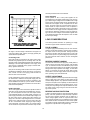
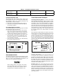
+6V Current Foldback. The overload and short-circuit pro-
tection circuit for the +6V output reduces the output current
limit as the output terminal voltage decreases. (The operating
region of the +6V output is enclosed by heavy lines in Figure
4.) The maximum rated output current is 2.5 A and the current
limit is factory-adjusted to operate at 2.75 A ± 5% when the
output is 6 volts. At lower output voltages, the circuit reduces
the maximum obtainable output current linearly until 1 A ±
15% flows when the output is shorted. The short-circuit cur-
rent can not be adjusted.
During the actual operation of the ±20V and +6V outputs, if a
load change causes the current limit to be exceeded, the OL
LED is lighted. If overload conditions occur, the ±20V supplies
will protect the load by limiting the current to 0.55 A and the
+6V supply will protect the load by reducing both voltage and
current simultaneously along the foldback locus as shown in
Figure 4. The ±20V and +6V supplies are self restoring; that
is, when the overload is removed or corrected, the output
voltage is automatically restored to the previously set value.
Operation Beyond Rated Output
The supply may be able to provide voltages and currents
greater than its rated maximum outputs if the line voltage is at
or above its nominal value. Operation can be extended up to
5% over the rated output without damage to the supply, but
performance can not be guaranteed to meet specifications in

1-8
Figure 3. Current Limit Characteristic of the 6V Supply
this region. If the line voltage is maintained in the upper end
of the input voltage range, however, the supply probably will
operate within its specifications
Connecting Load
Each load should be connected to the power supply output
terminals using separate pairs of connecting wires. This will
minimize mutual coupling effects between loads and takes full
advantage of the low output impedance of the supply. Load
wires must be of adequately heavy gauge to maintain satis-
factory regulation at the load.
Each pair of connecting wires should be as short as possible
and twisted or shielded to reduce noise pick-up. If a shield is
used, connect one end to the supply ground terminal and
leave the other end unconnected.
If load considerations require locating output power distribu-
tion terminals at a distance from the power supply, then the
power supply output terminals should be connected to the
remote distribution terminals by a pair of twisted or shielded
wires and each load should be connected to the remote distri-
bution terminals separately.
Parallel Operation
Two or more supplies can be connected in parallel to obtain a
total output current greater than that available from one sup-
ply. The total output current is the sum of the output currents
of the individual supplies. The output voltage controls of one
power supply should be set to the desired output voltage, and
the other supply set for a slightly larger output voltage. The
supply set to the lower output voltage will act as a constant
voltage source, while the supply set to the higher output will
act as a current-limited source, dropping its output voltage
until it equals that of the other supply. The constant voltage
source will deliver only that fraction of its rated output current
necessary to fulfill the total current demand.
Series Operation
Series operation of two or more power supplies can be
accomplished up to the output isolation rating of any one sup-
ply to obtain a higher voltage than that available from a single
supply. Series connected supplies can be operated with one
load across both supplies or with a separate load for each
supply. The power supply has a reverse polarity diode con-
nected across the output terminals so that if operated in
series with other supplies, damage will not occur if the load is
short-circuited or if one supply is turned on separately from its
series partners. When this connection is used, the output volt-
age is the sum of the voltages of the individual supplies. Each
of the individual supplies must be adjusted in order to obtain
the total output voltage.
LOAD CONSIDERATIONS
This section provides information on operating your supply
with various types of loads connected to its output.
PULSE LOADING
The power supply will automatically cross over from constant-
voltage to current-limit operation in response to an increase in
the output current over the preset limit. Although the preset
limit may be set higher than the average output current, high
peak currents (as occur in pulse loading) may exceed the pre-
set current limit and cause crossover to occur and degrade
performance.
REVERSE CURRENT LOADING
An active load connected to the supply may actually deliver a
reverse current to the supply during a portion of its operating
cycle. An external source can not be allowed to pump current
into the supply without risking loss of regulation and possible
damage to the output capacitor of the supply. To avoid these
effects, it is necessary to preload the supply with a dummy
load resistor so that the supply delivers current through the
entire operating cycle of the load devices.
OUTPUT CAPACITANCE
An internal capacitor across the output terminals of the supply
helps to supply high-current pulses of short duration during
constant-voltage operation. Any capacitance added externally
will improve the pulse current capability, but will decrease the
load protection provided by the current limiting circuit. A high-
current pulse may damage load components before the aver-
age output current is large enough to cause the current limit-
ing circuit to operate.
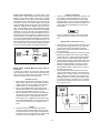
REVERSE VOLTAGE PROTECTION
A diode is connected across the output terminals with reverse
polarity. This diode protects the output electrolytic capacitors
and the series regulator transistors from the effects of a
reverse voltage applied across the output terminals. Since
series regulator transistors can not withstand reverse voltage
either, diodes are also connected across them. When operat-
ing supplies in parallel, these diodes protect an unenergized
supply that is in parallel with an energized supply.

1-9
Figure 4. Reverse Current Loading Solution

A-1
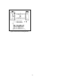
SERVICE INFORMATION
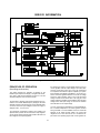
Figure A-1. Block Diagram
PRINCIPLES OF OPERATION
(Block Diagram Overview)
This section presents the principles of operation of the
E3630A Triple Output Power Supply. Throughout this discus-
sion, refer to both the block diagram of Figure A-1 and the
schematic diagrams at the rear of the manual.
The two primary windings of the power transformer are con-
nected in one of three different ways by setting the two slide
switches mounted on the circuit board. These switches select
one of the nominal ac input voltages for which the supply is
designed: 100 V, 115 V, or 230 V.
The transformer secondaries, together with rectifiers and
capacitor filters, provide raw dc for the three output regulator
circuits and for another regulator that provides reference and
bias voltages to the output regulators.
By comparing its output to a high-stability reference, the 0 to
+6-volt regulator holds its output voltage at the value deter-
mined by a front panel control. Any error in the actual output
as compared to the desired output is amplified by an opera-
tional amplifier and applied as feedback to control the con-
duction of a series regulator transistor. As a result, the voltage
across the series transistor varies so as to hold the output
voltage constant at the desired level. The high gain of the
voltage comparison amplifier and the stability of the reference
voltage ensure that input voltage or load current variations
have little effect on the output voltage.
The 0 to +6-volt output is protected by a current foldback lim-
iter to minimize dissipation in the series regulator transistor
during overloads. In a current foldback circuit, the current limit
depends on the output terminal voltage. The current limit
ranges from 2.75 A ± 5% at 6 volts to 1 A ± 15% with the out-
put shorted. The operating region of the +6-volt regulator out-

A-2
put is enclosed by a heavy line in Figure 3 of the operating
section. If the operating point reaches the diagonal current
limit line, a decrease in load resistance moves the operating
point down the line, reducing the output voltage and current.
Current foldback is controlled by a second operational ampli-
fier (current comparison amplifier) in the regulator that moni-
tors the dc output current. This current comparison amplifier
takes control of the output away from the voltage comparison
amplifier when the current reaches the design limit. Removing
the overload restores constant voltage operation auto-
matically.
The 0 to +20-volt regulator has a fixed current limit at 105% of
its 0.5 amp maximum rated output. The input ac line voltage
is first applied to the preregulator which operates in conjunc-
tion with the SCR control circuit (preregulator control circuit)
to rectify the tap switched AC voltage. This preregulator mini-
mizes the power dissipated in the series regulating elements
by controlling the dc level across the input filter capacitor,
depending on the output voltage. To achieve this, tap switch-
ing is accomplished by two SCRs and one bridge diode
(CR28, CR32 and CR26) and the SCR control circuit. This cir-
cuit allows the input capacitor to charge to one of two discrete
voltage levels depending on the output required.
When output voltage exceeds the reference level, the SCR
control circuit fires two SCRs that cause the input capacitor to
be charged to the voltage which is necessary for full output of
the supply. When the two SCRs are not fired, the bridge diode
CR26 conducts and half the voltage is applied to series pass
transistor Q9.
The 0 to -20-volt regulator is, in turn, similar to the +20-volt
regulator except that it resembles a complementary mirror
image of the latter. The output voltages of the +20-volt and -
20-volt supplies are both set by the same front panel control
and track each other within 1% in the fixed tracking ratio
mode. Precise tracking of the two outputs is achieved by
controlling the positive output conventionally and using that
output as the reference voltage for the negative output.
The reference and bias supply powers the operation amplifi-
ers and provides reference and bias voltages for the output
regulators. The display power circuit provides voltage which
is used by the A/D converter and display.
The turn-on/turn-off control circuit prevents output transients
when the supply is turned on or off. It does this by delaying
the application of certain bias and reference voltages at turn-
on and removing them shortly after turn-off.
Three meter push-button switches select which of the sup-
plies has its output voltage and current indicated on the front
panel meters.
Diode CR2, CR3, and CR4 are connected across the output
terminals in reverse polarity. They protect the output elec-
trolytic capacitor and the series regulator transistors from a
reverse voltage applied across the output terminals.
MA INTENANCE
INTRODUCTION
This section provides performance test, troubleshooting infor-
mation, and adjustment and calibration procedures. The fol-
lowing operation verification tests comprise a short procedure
to verify that the power supply is performing properly, without
testing all specified parameters.
If a fault is detected in the power supply while making the
performance check or during normal operation, proceed to
the troubleshooting procedures. After troubleshooting, per-
form any necessary adjustments and calibrations. Before
returning the power supply to normal operation, repeat the
performance check to ensure that the fault has been properly
corrected and that no other faults exist.
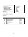
Test Equipment Required
The following Table A-1 lists the equipment required to per-
form the various procedures described in this section.
Table A-1. Test Equipment Required
TYPE REQUIRED CHARACTERISTICS USE RECOMMENDED
MODEL
Oscilloscope Sensitivity : 100 V
Bandwidth : 20 MHz/100 MHz
Display transient response and ripple
and noise waveforms.
Agilent 54600A
RMS Voltmeter True rms, 20 MHz bandwidth
Sensitivity : 1 mV
Accuracy : 5%
Measure rms ripple and noise
voltage.
Multimeter Resolution : 100 nV
Accuracy : 0.0035%
Measure dc voltages. Agilent 34401A
Electronic Load Voltage Range : 240 Vdc
Current Range : 10 Adc
Open and short switches
Transient on/off
Measure load and line regulation. Agilent 6063A
Resistive Loads (R
L
) 40 20 W, 2.4 20 W Measure ripple and noise.

A-3
Operation Verification Tests
The followin
g
tests assure that the power suppl
y
is per-
formin
g
properl
y
. The
y
do not, however, check all the speci-
fied parameters tested in the complete performance test
described below. Proceed as follows:
a. Perform turn-on checkout procedure
g
iven in pa
g
e 1-7.
b. Perform the load re
g
ulation performance tests
g
iven in
the followin
g
para
g
raphs.
Line Volta
g
e Option Conversion
To convert the suppl
y
from one line volta
g
e option to another,
the followin
g
three steps are necessar
y
:
a. After makin
g
certain that the line cord is disconnected
from a source of power, remove the top cover from the
suppl
y
and set the two sections of the line volta
g
e selec-
tor switch for the desired line volta
g
e (see Fi
g
ure A-2).
b. Check the ratin
g
of the installed fuse and replace it with
the correct value, if necessar
y
. For Option OE3, use a
slow-blow 1.0-amp fuse. For standard and Option OE9,
use a slow-blow 1.6-amp fuse.
c. Mark the instrument clearl
y
with a ta
g
or label indicatin
g
the correct line volta
g
e to be used.
Fi
g
ure A-2. Line Volta
g
e Selector (set for 115 Vac)
PERFORMANCE TESTS
The followin
g
para
g
raphs provide test procedures for verif
y
-
in
g
the power suppl
y
's compliance with the specifications of
Table 1. Proceed to the troubleshootin
g
procedures if
y
ou
observe an
y
out of specification performance.
Before appl
y
in
g
power to the suppl
y
, make certain
that its line volta
g
e selector switch (S2) is set for the
line volta
g
e to be used. (See CAUTION notice in
operatin
g
section for additional information on S2.)
General Measurement Techniques
Connectin
g
Measurin
g
Devices. To achieve valid results
when measurin
g
load re
g
ulation, ripple and noise, and tran-
sient response time of the suppl
y
, measurin
g
devices must be
connected as close to the output terminals as possible. A
measurement made across the load includes the impedance
of the leads to the load. The impedance of the load leads can
easil
y
be several orders of the ma
g
nitude
g
reater than the
suppl
y
impedance and thus invalidate the measurement. To
avoid mutual couplin
g
effects, each measurin
g
device must
be connected directl
y
to the output terminals b
y
separate
pairs of leads.
When performance measurements are made at the front ter-
minals (Fi
g
ure A-3) the load should be plu
gg
ed into the front
of the terminals at (B) while the monitorin
g
device is con-
nected to a small lead or bus wire inserted throu
g
h the hole in
the neck of the bindin
g
post at (A). Connectin
g
the measurin
g
device at (B) would result in a measurement that includes the
resistance of the leads between the output terminals and the
point of connection.
Fi
g
ure A-3. Front Panel Terminal Connections
Selectin
g
Load Resistors. Power suppl
y
specifications are
checked with a full load resistance connected across the sup-
pl
y
output. The resistance and watta
g
e of the load resistor,
therefore, must permit operation of the suppl
y
at its rated out-
put volta
g
e and current. For example, a suppl
y
rated at 20
volts and 0.5 amperes would require a load resistance of 40 Ω
at the rated output volta
g
e. The watta
g
e ratin
g
of this resistor
would have to be at least 20 watts.
Electronic Load. Some of the performance test procedures
use an electronic load to test the suppl
y
quickl
y
and accu-
ratel
y
. An electronic load is considerabl
y
easier to use than a
load resistor. It eliminates the need for connectin
g
resistors or
rheostats in parallel to handle the power, it is much more sta-
ble than a carbon-pile load. It is easier to switch between load
conditions as required for the load re
g
ulation and load tran-
sient response tests.
Current Samplin
g
Resistor (Shunt)
100 mΩ 0.1% 15 W Measure output current
Variable Volta
g
e
Auto Transformer
Ran
g
e : 85-130 and 200-260
Volts
Var
y
ac input.
Table A-1. Test Equipment Required (Cont’d)

A-4
Output Current Measurement. For accurate output current
measurements, a current sampling resistor should be inserted
between the load and the output of the supply. To simplify
grounding problems, one end of this sampling resistor should be
connected to the same output terminal of the supply which will
be shorted to ground. An accurate voltmeter is then placed
across the sampling resistor and the output current calculated by
dividing the voltage across the sampling resistor by its ohmic
value. The total resistance of the series combination should be
equal to the full load resistance as determined in the preceding
paragraphs. Of course, if the value of the sampling resistor is
very low when compared to the full load resistance, the value of
the sampling resistor may be ignored. The meter shunt recom-
mended in Table A-1, for example, has a resistance of only 100
m and can be neglected when calculating the load resistance
of the supply. Figure A-4 shows a four terminal meter shunt. The
load current through a shunt must be fed from the extremes of
the wire leading to the resistor while the sampling connections
are made as close as possible to the resistance portion itself.
Figure A-4. Current Sampling Resistor Connections
Rated Output, Tracking, Meter Accuracy, and Cur-
rent Limit
To check that all supplies will furnish their maximum rated
output voltage and current, that the ±20V outputs track each
other, that the front panel meters are accurate, and that the
current limit circuits function, proceed as follows:
Voltmeter Accuracy
a. With no loads connected: turn on the supply, connect a
digital voltmeter between the +20V terminal and common
(COM), and set the ±20V VOLTAGE control so that the
DVM indication is as near as possible to 17 volts.
b. Push the +20V METER switch on and check the front
panel voltmeter indication. It should be within ±(0.5% +2
counts) of the DVM indication (16.90V to 17.10V).
c. Set the TRACKING RATIO control to the FIXED position,
and check the +20V and -20V ranges of the front panel
voltmeter similarly by connecting the DVM to each of
these outputs in turn, setting the ±20V VOLTAGE control
for a 20 volts DVM indication, and verifying that the panel
meter is accurate within ±(0.5%+ 2 counts) (19.7V to
20.3V).
Tracking
d. Connect the DVM to the +20V output, set the ±20V
VOLTAGE control for a DVM indication of 20 volts, and
reconnect the DVM to the -20V output without disturbing
the voltage control. The voltage at the -20V output should
be within 1% of the +20V output (19.8V to 20.2V).
Variable Tracking Ratio
e. Leave the ±20V VOLTAGE control set as in step (d), and
use a DVM to monitor the voltage of the -20V supply
while adjusting the TRACKING RATIO control over its
VARIABLE range. The -20V supply should be capable of
being adjusted from less than 0.5 volts to between 19 to
21 volts. Return the TRACKING RATIO control to the
FIXED position.
Leave the TRACKING RATIO control in the FIXED
position throughout the reminder of the performance
test.
Rated Output and Ammeter Accuracy
f. Connect two 40 20 W load resistors across both of the
20V outputs of the supply and set the ±20V VOLTAGE
control for ±20V outputs. (All supplies must be fully
loaded while checking the rated output voltage and cur-
rent of each supply.)
g. Connect the test setup shown Figure A-5 to the +6V output.
Make the total resistance of R
L
and the current sampling
resistor equal to 2.4 to permit operating the output at full
load. R
L
should have a power rating of at least 20 watts.
h. Close the switch and set the +6V VOLTAGE control so that
the DVM indicates a voltage drop across the current sam-
pling resistor that corresponds to a current of 2.5 amps.
i. Push the +6V METER switch and verify that the front
panel ammeter indication is within ±(0.5%+2 counts) of
2.5 amps (2.47A to 2.53A).
j. Check the rated output and ammeter accuracy of the
+20V and -20V supplies similarly by connecting the test
setup of Figure A-5 to each output in turn. For each 20V
supply: make the total resistance of R
L
and the current
sampling resistor 40 , set the ±20V VOLTAGE control
for a current indication on the DVM of 0.5 A, check that
the panel meter indication is within ±(0.5%+2 counts) of
0.5 A (0.48A to 0.52A).
Figure A-5. Output Current, Test Set UP

A-5
Current Limit
k. Disconnect all loads from the suppl
y
.
l. Connect the test setup shown in Fi
g
ure A-5 to the +20-
volt output. Substitute a short for R
L
and leave the load
circuit switch open.
m. Set the volta
g
e of the ±20V supplies to 20 volts.
n. Close the load switch and determine the current flow
throu
g
h the current samplin
g
resistor (meter shunt) b
y
measurin
g
its volta
g
e drop with the DVM. The current
should be 0.55A±5% (0.5225A to 0.5775A).
o. Check the current limit of the -20V suppl
y
in the same
wa
y
. Its short-circuit current should also be 0.55A±5%
(0.5225A to 0.5775A).
p. Connect the test setup shown in Fi
g
ure A-5 to the +6V
output. Close the switch, set the total resistance of R
L
and
the current samplin
g
resistor to an initial value of 2.4 Ω or
g
reater, and set the output volta
g
e to 6 volts.
q. Reduce the value of R
L
g
raduall
y
while observin
g
the out-
put current indicated b
y
the DVM. The current should
increase to a maximum of 2.75A±5% (2.6125A to
2.8875A) before it be
g
ins to decrease.
r. Connect a short across R
L
and then recheck the current
indicated b
y
the DVM. The short-circuit current of this out-
put should be 1A±15% (0.85A to 1.15A). Disconnect the
test setup from the suppl
y
.
Load Re
g
ulation (Load Effect)
Definition: The chan
g
e, E
OUT
, in the static value of dc out-
put volta
g
e resultin
g
from a chan
g
e in load resistance from
open circuit to the value that
y
ields maximum rated output
current (or vice versa).
To check the load re
g
ulation:
a. Connect the test equipment across the output of the
+20V suppl
y
as shown in Fi
g
ure A-6. Operate the elec-
tronic load in constant current mode and set its current to
the full rated value of the +20V suppl
y
.
b. Turn on the suppl
y
and adjust its volta
g
e to its maximum
rated value.
c. Record the volta
g
e indicated on the DVM.
d. Operate the electronic load in open (input off) mode and
recheck the DVM indication after readin
g
settles. It should
be within 0.01% plus 2mV of the readin
g
in step (c).
e. Repeat steps (a) throu
g
h (d) for each of the remainin
g
suppl
y
outputs.
Fi
g
ure A-6. Basic Test Setup
Line Re
g
ulation (Source Effect)
Definition: The chan
g
e, E
OUT
, in the static value of dc output
volta
g
e resultin
g
from a chan
g
e in ac input volta
g
e from a
minimum to a maximum value (±10% of nominal volta
g
e).
To check the line re
g
ulation:
a. Connect a variable autotransformer between the input
power source and the power suppl
y
line plu
g
.
b. Connect the test equipment across the output of the
+20V suppl
y
as shown in Fi
g
ure A-6. Operate the elec-
tronic load in constant current mode and set its current to
the full rated value of the +20V suppl
y
.
c. Adjust the autotransformer for a low line input (-10% of
nominal volta
g
e).
d. Turn on the power, adjust the output of the suppl
y
to its
maximum rated volta
g
e, and record the DVM indication.
e. Adjust the autotransformer for hi
g
h line volta
g
e input
(+10% of nominal volta
g
e) and recheck the DVM indica-
tion. It should be within 0.01% plus 2mV of the readin
g
in
step (d).
f. Repeat steps (b) throu
g
h (e) for each of the remainin
g
suppl
y
outputs.
Ripple and Noise
Definition: Ripple and noise are measured in the rms or peak-
to-peak value over a 20 Hz to 20 MHz bandwidth. Fluctuations
below the lower frequenc
y
limit are treated as drift.
RMS Measurement
The rms measurement is not an ideal representation of the
noise, since fairl
y
hi
g
h output noise spikes of short duration
could be present in the ripple and not appreciabl
y
increase
the rms value.
To measure the ripple and noise of the rms value on each
output suppl
y
output:
a. Connect the test equipment across the output of the
+20V suppl
y
as shown in Fi
g
ure A-7.
b. Turn on the suppl
y
and push +20V METER switch.
c. Turn up output volta
g
e to the full rated value.
d. Check that the rms noise volta
g
e at the true rms voltme-
ter is less than 0.35mV.
e. Repeat for the remainin
g
suppl
y
outputs.
Fi
g
ure A-7. Ripple and Noise rms Measurement Test
Setup

A-6
Peak-to-Peak Measurement
The peak-to-peak measurement is particularly important for
applications where noise spikes could be detrimental to a
sensitive load, such as logic circuitry.
To measure the ripple and noise of the peak-to-peak value on
each output supply output:
a. Connect the test equipment across the output of the
+20V supply as shown in Figure A-7, but replace the true
rms voltmeter with the oscilloscope.
b. Turn on the supply and push +20V METER switch.
c. Turn up output voltage to the full rated value.
d. Set the oscilloscope to AC mode and bandwidth to 20
MHz.
e. Check that the peak-to-peak noise is less than 1.5 mV.
f. Repeat for the remaining supply outputs.
Common Mode Current (CMI)
Definition : Common mode current is that ac current compo-
nent which exists between any or all supply or output lines
and chassis ground.
To measure the common mode current:
a. Connect the full load for +6V output.
b. Connect a 100 k resistor(R
S
) and a 2200 pF capacitor
in parallel between common terminal(COM) and chassis
ground.
c. Connect the DVM across R
S
.
d. Turn on the supply.
e. Record the voltage across R
S
and convert it to current by
dividing this voltage by R
S
.
f. Check that the current is less than 1 A.
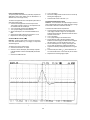
Load Transient Response Time
Definition : This is the time for the output voltage to return to
within a specified band around its voltage following a change
from full load to half load or half load to full load.
To measure the load transient response time:
a. Connect the test equipment across the output of the
+20V supply as shown in Figure A-6, but replace the
DVM with the oscilloscope. Operate the electronic load in
constant current mode.
b. Turn on the supply.
c. Turn up output voltage to the full rated value.
d. Set the electronic load to transient operation mode
between one half of supply's full rated value and supply's
full rated value at a 1 KHz rate with 50% duty cycle.
e. Set the oscilloscope for ac coupling, internal sync and
lock on either the positive or negative load transient.
f. Adjust the oscilloscope to display transients as in Figure
A-8.
g. Check that the pulse width (t
2
-t
1
) of the transients at 15
mV from the base line is no more than 50 sec as shown.
h. Repeat for the remaining supply outputs.
Figure A-8. Load Transient Response Time Waveform

A-7
Stability (Drift)
Definition: The change in output voltage (dc to 20 Hz) for the
first 8 hours following a 30-minute warm-up period with con-
stant input line voltage, constant load resistance and constant
ambient temperature.
To measure the stability:
a. Connect the test equipment across the output of the
+20V supply as shown in Figure A-6.
b. Operate the electronic load in constant current mode and
set its current to the full rated value of power supply.
c. Turn on the supply.
d. Turn up output voltage to the full rated value as read on
the digital voltmeter.
e. After a 30-minute warm-up, note the voltage on DVM.
f. The output voltage reading should deviate less than 0.1%
plus 5 mV from the reading obtained in step e over a
period of 8 hours.
g. Repeat for the remaining supply outputs.
TROUBLESHOOTING
Before attempting to troubleshoot the power supply, ensure
that the fault is with the supply and not with an associated
piece of equipment. You can determine this without removing
the covers from the power supply by using the appropriate
portions of the "Performance Test" paragraph.
Before applying power to the supply, make certain
that its line voltage selector switch (S2) is set for the
line voltage to be used.
Initial Troubleshooting Procedure
If a malfunction is found, follow the steps below:
a. Disconnect input power from the supply and remove all
loads from the output.
b. Table A-2 lists the symptoms and probable causes of sev-
eral possible troubles. If the symptoms is one of those
listed, make the recommended checks.
c. If none of the symptoms of Table A-2 apply, proceed to
Table A-3. This table provides an initial troubleshooting
procedure that also directs you to the more detailed pro-
cedures which follow it.
The numbered test points referred to in the troubleshooting
procedures are identified on the circuit schematic at the rear
of the manual.
Open Fuse Troubleshooting
Although transients or fatigue can cause a fuse to blow, it is a
good idea to inspect the unit for obvious shorts such as dam-
aged wiring, charred components, or extraneous metal parts
or wire clippings in contact with circuit board conductors
before replacing the fuse. The rating of the correct replace-
ment fuse depends on the line voltage option of the instru-
ment: for Option OE3, use a slow-blow 1.0-amp fuse and
standard and Option OE9, use a slow-blow 1.6-amp fuse.
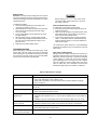
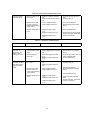
Table A-2. Miscellaneous Troubles
SYMPTOM CHECK - PROBABLE CAUSE
High ripple a. Check operating setup for ground loops.
b. Check main rectifiers(CR1, CR25, CR26) for open.
c. Supply may be operating in current limit mode. Check current limit adjustment, steps (k)
thru (r) on page A-5.
Will not current limit Check for open OR-gate diodes (CR7, CR11, CR18) or defective current limit amplifier
(U2, U6, U8).
Poor load and line regulation a. Check bias and reference voltages, Table A-4.
b. Check main rectifiers and filters for opens.
Oscillation or poor transient
response time
a. High frequency oscillations (above 50 kHz) can be caused by an open C11, C20, or C25.
b. A defective output capacitor (C2, C3, or C4) can cause oscillations in one of many frequency
ranges.
c. Oscillation only in the current limiting mode can be caused by an open C12, C19, or C24.
Transient voltage overshoot at
turn-on or turn-off
a. Overshoot only in the -20V supply can be caused by a shorted Q3.
b. Overshoot in all three supply outputs can be caused by an open Q2 or a shorted Q6.
Excessive heat a. Check preregulator control circuit. Refer to Table A-8 and Table A-9.
b. Check CR27, CR28, CR31, CR32 for short.
Output Voltage clamped
above 10V for ± 20V output
Check preregulator control circuit. Refer to Table A-8 and Table A-9.

A-8
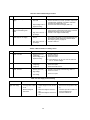
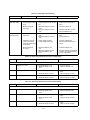
Table A-3. Initial Trobleshooting Procedure
STEP ACTION RESPONSE NEXT ACTION
1 Check output voltage of +20V
supply.
a. Normal
b. Zero volts
c. Output voltage lower or
higher than rating
a. Proceed to step (2).
b. Check ac line fuse (F1). If blown, proceed to "Open Fuse
Troubleshooting" paragraph. If not blown, check bias
and reference voltages (Table A-4).
c. Check bias and reference voltages (Table A-4).
2 Check output voltage of -20V
supply in fixed tracking ratio
mode.
a. Normal
b. High, low, or zero out-
put voltage.
a. If +20V and -20V outputs are both normal with no load, a
supply might be current limiting under load. To check this
adjustment see steps (l) thru (p) on page A-4.
b. Proceed to -20V supply troubleshooting.
3 Check output of +6V supply. a. Normal
b. High, low, or zero out-
put voltage.
a. If the output of this supply is normal unloaded but its volt-
age falls when loaded, check the current limit adjust-
ment, steps (q) thru (t) on page A-4.
b. Proceed to Table A-7.
Table A-4. Bias and Reference Voltage Check
STEP ACTION RESPONSE NEXT ACTION
1 Check +12V bias. a. Normal (+12V ± 5%)
b. Voltage high
c. Output voltage lower or
higher than rating
a. Proceed to step (3).
b. Check U3 for short.
c. Check U3 for open.
Note: A short within U2, U6, U8, U9 or U14 can cause low
+12V or -12V bias voltages.
2 Check -5V reference. a. Normal (-5V ± 2%)
b. Voltage high
c. Voltage low
a. Proceed to step (3).
b. Check U5 for open.
c. Check U5 and Q2 for short.
3 Check -12V bias. a. Normal (-12V ± 5%)
b. High voltage
c. Low voltage
a. Proceed to +20V supply troubleshooting, Table A-5.
b. Check U1 for short.
c. Check U1 for open.
Table A-5. +20V Supply Troubleshooting
SYMPTOM STEP - ACTION RESPONSE PROBABLE CAUSE
High output voltage
(higher than rating)
1. Attempt to turn off Q9 by
shorting emitter-to-base
of Q9.
2. Measure voltage at
base of Q5.
a. Output voltage remains high.
b. Output voltage becomes near zero
volt.
a. Measured voltage is less than 0
volt.
b. Measured voltage is more than 0
volt.
a. Q9 shorted.
b. Remove short and proceed to step
(2).
a. Check for open CR13 or R36 and
check for defective U6A.
b. Check for defective Q5.

A-9
Low output voltage
(lower than rating)
1. Measure voltage at the
base of Q5.
2. Eliminate current limit
circuit as a source of
trouble by disconnecting
anode of CR11.
3. Measure voltage at pin 3
of U6.
a. Measured voltage is less than 0
volt.
b. Measures voltage is more than 0
volt.
a. Output voltage increases.
b. Output voltage remains low.
a. Measured voltage is near
-0.7V.
b. Measured voltage is zero volt.
c. Measured voltage is near
+0.7V.
a. Check for open Q9, Q6, R26, or
CR5.
b. Proceed to step (2).
a. Check for U6B defective.
b. Reconnect lead and proceed to
step (3).
a. Check for defective U6A.
b. Check for CR14 or CR15 shorted.
c. Check for open R39, shorted R36,
or leaky or shorted C7.
Table A-5. +20V Supply Troubleshooting (Cont’d)
Table A-6. -20V Supply Troubleshooting
SYMPTOM STEP - ACTION RESPONSE PROBABLE CAUSE
The +20V supply must operate properly before troubleshooting the -20V supply.
High output voltage
(more than 1%
greater than +20V
supply in fixed
tracking ratio mode)
1. Attempt to turn off Q8 by
shorting emitter-to-base
of Q8.
2. Measure voltage at
base of Q7.
a. Output voltage remains high.
b. Output voltage becomes near zero
volt.
a. Measured voltage is more than
0 volt.
b. Measured voltage is less than
0 volt.
a. Q8 shorted.
b. Remove short and proceed to
step (2).
a. Check for open CR20 or R14 and
check for defective U8A.
b. Check for defective Q7.
Low output voltage
(more than 1% lower
than +20V supply in
fixed tracking ratio
mode)
1. Measure voltage at the
base of Q7.
2. Eliminate current limit
circuit as a source of
trouble by disconnecting
anode of CR18.
3. Measure voltage at pin 3
of U8.
a. Measured voltage is more than 0
volt.
b. Measured voltage is less than
0 volt.
a. Output voltage increases.
b. Output voltage remains low.
a. Measured voltage is near
+0.7V.
b. Measured voltage is zero volt.
c. Measured voltage is near
-0.7V.
a. Check for open Q8, Q3, and R24.
b. Proceed to step (2).
a. Check for U8B defective.
b. Reconnect lead and proceed to
step (3).
a. Check for defective U8A.
b. Check for shorted CR21 and
CR22.
c. Check for open R15, shorted R41,
or leaky or shorted C6.

A-10
Table A-7. +6V Supply Troubleshooting
SYMPTOM STEP - ACTION RESPONSE PROBABLE CAUSE
The +20V supply must operate properly before troubleshooting the -20V supply.
High output voltage
(higher than rating)
1. Attempt to turn off Q1 by
shorting emitter-to-base
of Q1.
2. Measure voltage at
base of Q4.
a. Output voltage remains high.
b. Output voltage becomes near zero
volt.
a. Measured voltage is more than
-0.6V.
b. Measured voltage is less than
-0.6V.
a. Q1 shorted.
b. Remove short and proceed to
step 2.
a. Check for defective Q4.
b. Check for open CR6, R11 and
check for defective U2A.
Low output voltage
(lower than rating)
1. Measure voltage at the
base of Q4.
2. Eliminate current limit
circuit as a source of
trouble by disconnecting
anode of CR7.
3. Measure voltage at
pin 3 of U2.
a. Measured voltage is less than
-0.6V.
b. Measured voltage is more than
-0.6V.
a. Output voltage increases.
b. Output voltage remains low.
a. Measured voltage is near
-0.7V.
b. Measured voltage is zero volt.
c. Measured voltage is near
+0.7V.
a. Check for open Q1, Q6, R25, or
CR5.
b. Proceed to step (2).
a. Check for U2B defective.
b. Reconnect lead and proceed to
step (3).
a. Check for defective U2A.
b. Check for CR9 and CR10 shorted.
c. Check for open R29, shorted R11,
or leaky or shorted C5.
Table A-8. +20V Preregulator/Control Circuit Troubleshooting
STEP ACTION RESPONSE PROBABLE CAUSE
Set output voltage at 12V+0.5V.
1 Measure pin 1 of U14. a. Measured voltage is -12V.
b. Measured voltage is near
+4.3V.
a. Proceed to step (2).
b. Check for defective U14A.
2 Measure pin 1 of U13. a. Measured voltage is near +1V
b. Measured voltage is near 0V.
a. Check for defective U13 or
CR12.
b. Check for open Q11 or R81.
3 Measure pin 1 of U11. a. Measured voltage is near +1V
b. Measured voltage is near 0V.
a. Check for defective U11.
b. Check for open Q11 or R82.
Table A-9. -20V Preregulator/Control Circuit Troubleshooting
STEP ACTION RESPONSE PROBABLE CAUSE
Set output voltage at -12V-0.5V.
1 Measure pin 7 of U14. a. Measured voltage is -12V.
b. Measured voltage is near
+4.3V.
a. Proceed to step (2).
b. Check for defective U14B.
2 Measure pin 1 of U12. a. Measured voltage is near +1V
b. Measured voltage is near
+4.3V.
a. Check for defective U12 or
CR31.
b. Check for open Q10 or R56
3 Measure pin 1 of U10. a. Measured voltage is near +1V
b. Measured voltage is near 0V.
a. Check for defective U10 or
CR27.
b. Check for open Q10 or R55.

A-11
ADJUSTMENT AND CALIBRATION
Current Limit Adjustment
+6V Supply. To adjust the current limit circuit in the +6V sup-
ply, proceed as follows:
a. Check the setting of the current limit by performing steps
(p) and (q) on page A-5. (Be sure to set the output voltage
to 6 volts.) If reducing the load resistance permits the cur-
rent to exceed 2.9 A, stop, turn R6 slightly clockwise, and
repeat the test. If, instead, the current begins to fall before
it reaches 2.6 A, turn R6 slightly counter clockwise and
repeat the test.
b. Recheck the setting and readjust R6 until the test shows
that the current limit circuit begins to reduce the current
when a decreasing load resistance increases it to 2.75 A
± 5%.
Meter Calibration
Panel Voltmeters. To calibrate voltmeter, proceed as follows:
a. Connect DVM across +20V output terminal and COM ter-
minal of the supply.
b. Turn on the supply.
c. Set the output voltage below 18V (ex, 15V), and adjust
R11 on the display board until front panel VOLTS display
reads exactly DVM value. Next, set the output voltage
above 20V (ex, 21V) and adjust R17 on the display board
until front panel VOLTS display reads exactly DVM value.
No other voltage output needs to be calibrated after
calibrating the voltmeter of +20V output.
Panel Ammeter. To calibrate ammeter for +20V output and -
20V output, proceed as follows:
a. Connect R
S
between +20V output terminal and COM ter-
minal and connect DVM across R
S
.
b. Push +20V meter switch and turn ±20V VOLTAGE control
fully clockwise.
c. Turn on the supply and adjust R5 on the display board
until front panel AMPS display reads exactly DVM value
divided by Rs.
d. To calibrate the ammeter for +6V output, select +6V
meter switch and turn +6V VOLTAGE control fully clock-
wise.
e. Adjust R61 on the main board until front panel AMPS dis-
play reads exactly DVM value divided by Rs.
Page is loading ...
Page is loading ...
Page is loading ...
Page is loading ...
Page is loading ...
Page is loading ...
Page is loading ...
-
 1
1
-
 2
2
-
 3
3
-
 4
4
-
 5
5
-
 6
6
-
 7
7
-
 8
8
-
 9
9
-
 10
10
-
 11
11
-
 12
12
-
 13
13
-
 14
14
-
 15
15
-
 16
16
-
 17
17
-
 18
18
-
 19
19
-
 20
20
-
 21
21
-
 22
22
-
 23
23
-
 24
24
-
 25
25
-
 26
26
-
 27
27


Agilent Technologies E3630A User manual
- Category
- Power supply units
- Type
- User manual
Ask a question and I''ll find the answer in the document
Finding information in a document is now easier with AI
Related papers
-
Agilent Technologies E3620A Operating and Service Manual
-
-
-
-
-
Agilent Technologies 34450A User manual
-
Agilent Technologies E3634A User manual
-
-
-