Tripp Lite SmartPro SMART500RT1U Owner's manual
- Type
- Owner's manual

1
Owner’s Manual
Warranty
Registration
Register online today for a
chance to win a FREE Tripp Lite
product! www.tripplite.com/warranty
1111 W. 35th Street, Chicago, IL 60609 USA • www.tripplite.com/support
Important Safety Instructions 2
Mounting 4
Quick Installation 5
Optional Installation 6
Basic Operation 7
Storage and Service 10
Battery Replacement 11
Warranty Registration 12
Español 13
Français 25
SmartPro
®
1U Rackmount
Intelligent, Line-Interactive UPS Systems
120V Output • 500VA – 1000VA
SMART500RT1U
Series: AG-0097
SMART750RM1U
Series: AGSM8269
SMART1000RM1U
Series: AGSM5060
Not suitable for mobile applications.
Copyright © 2014 Tripp Lite. All rights reserved. SmartPro
®
is a registered trademark of Tripp Lite.
13-12-130-93328A.indb 1 1/6/2014 2:59:12 PM

2
Important Safety Instructions
SAVE THESE INSTRUCTIONS
This manual contains important instructions that should be followed during the installation,
operation and storage of this product. Failure to heed these warnings may affect the warranty.
UPS Location Warnings
• Use caution when lifting the UPS. Because of the considerable weight of all rackmount UPS
systems, at least two people should assist in lifting and installing them.
• Install the UPS indoors, away from excess moisture or heat, dust or direct sunlight.
• For best performance, the ambient temperature near the UPS should be between 0° C and 40° C
(between 32° F and 104° F).
• Leave adequate space around all sides of the UPS for proper ventilation. Do not obstruct its vents
or fan openings.
• When mounting the UPS system in a tower orientation, make sure the LED Screen panel is at the
top of the UPS, not at the bottom.
• Do not mount unit with its front or rear panel facing down (at any angle). Mounting in this manner
will seriously inhibit the unit’s internal cooling, eventually causing product damage not covered
under warranty.
UPS Connection Warnings
• The UPS contains its own energy source (battery). The output terminals may be live even when
the UPS is not connected to an AC supply.
• Connect the UPS to a properly grounded AC power outlet. Do not modify the UPS’s plug in a way
that would eliminate the UPS’s connection to ground. Do not use adapters that eliminate the
UPS’s connection to ground.
• Do not plug the UPS into itself; this will damage the UPS and void your warranty.
• If you are connecting the UPS to a motor-powered AC generator, the generator must provide
filtered, frequency-regulated computer-grade output. Connecting the UPS to a generator will void
its Ultimate Lifetime Insurance.
Equipment Connection Warnings
• Use of this equipment in life support applications where failure of this equipment can reasonably
be expected to cause the failure of the life support equipment or to significantly affect its safety
or effectiveness is not recommended. Do not use this equipment in the presence of a flammable
anesthetic mixture with air, oxygen or nitrous oxide.
• Do not connect surge suppressors or extension cords to the output of the UPS. This might
damage the UPS and may affect the surge suppressor and UPS warranties.
13-12-130-93328A.indb 2 1/6/2014 2:59:12 PM

3
Battery Warnings
• Batteries can present a risk of electrical shock and burn from high short-circuit current. Observe
proper precautions. Do not dispose of the batteries in a fire. Do not open the UPS or batteries.
Do not short or bridge the battery terminals with any object. Unplug and turn off the UPS before
performing battery replacement. Use tools with insulated handles. There are no user-serviceable
parts inside the UPS. Battery replacement should be performed only by authorized service
personnel using the same number and type of batteries (Sealed Lead-Acid). The batteries
are recyclable. Refer to your local codes for disposal requirements or visit www.tripplite.com/
UPSbatteryrecycling for recycling information. Tripp Lite offers a complete line of UPS System
Replacement Battery Cartridges (R.B.C.).Visit Tripp Lite on the Web at www.tripplite.com/support/
battery/index.cfm to locate the specific replacement battery for your UPS. The RBC Type can also
be found on the label affixed to the Battery Retention Plate.
• During hot-swap battery replacement, the UPS will not provide backup power in the event of a
blackout or other power interruptions.
• Do not operate the UPS without batteries.
• Servicing of batteries should be performed or supervised by personnel knowledgeable about
batteries and required precautions.
• When replacing batteries, replace with the same type and number of batteries or battery packs.
• CAUTION: Do not dispose of batteries in a fire. The batteries may explode.
• CAUTION: Do not open or mutilate batteries. Released electrolyte is harmful to the skin and eyes. It
may be toxic.
• CAUTION: A battery can present a risk of electrical shock and high short-circuit current. The
following precautions should be observed when working on batteries:
o Remove watches, rings or other metal objects.
o Use tools with insulated handles.
o Wear rubber gloves and boots.
o Do not lay tools or metal parts on top of batteries.
o Determine if battery is inadvertently grounded. If inadvertently grounded, remove source from
ground. Contact with any part of a grounded battery can result in electric shock. The likelihood of
such shock can be reduced if such grounds are removed during the installation and maintenance
(applicable to equipment and remote battery supplies not having a grounded supply circuit).
• For pluggable equipment, the socket-outlet shall be installed near the equipment and shall be easily
accessible.
Important Safety Instructions
13-12-130-93328A.indb 3 1/6/2014 2:59:12 PM

4
1
1
2
2
D
D
D
D
A
A
B
B
C
C
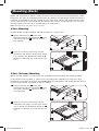
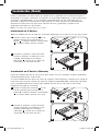
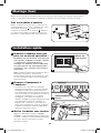
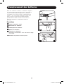
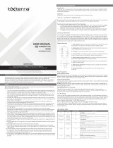
Mounting (Rack)
Mount your equipment in either a 4-post or 2-post rack or rack enclosure (see below for 2-post
mounting). The user must determine the fitness of hardware and procedures before mounting. If
hardware and procedures are not suitable for your application, contact the manufacturer of your
rack or rack enclosure. The procedures described in this manual are for common rack and rack
enclosure types and may not be appropriate for all applications.
Note: The illustrations may differ from your model.
4-Post Mounting
All UPS models include hardware required to mount in a 4-post rack.
1
Attach mounting ears
A
to the front
mounting holes of your equipment
B
using
the screws provided
C
. The ears should
face forward.
2
Using an assistant if necessary, lift your
equipment and mount it to the rack. Attach
it by screwing the appropriate hardware
D
through its mounting ears and into the rack
rails.
2-Post (Telecom) Mounting
Mount 1U UPS models in 2-post racks with included hardware following the procedure below.
If you mount 2U UPS models in 2-post racks, they require the addition of a Tripp Lite 2-Post
Rackmount Installation Kit (model: 2POSTRMKITWM, sold separately). See Installation Kit owner’s
manual for installation procedure for 2U UPS models.
1
Attach mounting ears
A
to the front
mounting holes of your equipment
B
using
the screws provided
C
. The ears should
face backward.
2
Using an assistant if necessary, lift your
equipment and mount it to the rack. Attach
it by screwing the appropriate hardware
D
through its mounting ears and into the rack
rails.
13-12-130-93328A.indb 4 1/6/2014 2:59:17 PM

5
A
A
B
B
2
3
1
NEMA 5-15P
Plug Shown
SMART1000RM1U
Shown
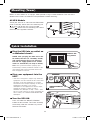
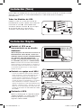
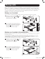
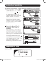
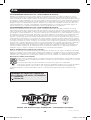
Mounting (Tower)
Mount all UPS models in an upright, tower position using included hardware. The user must
determine the fitness of hardware and procedures before mounting.
All UPS Models
Stand your UPS on its side with the LED/Control
panel at the top. Attach one rack mounting ear
A
to each side of the UPS using included
screws
B
. Attach the rack mounting ears to the
floor with user-supplied hardware.
Quick Installation
1
Plug the UPS into an outlet on
a dedicated circuit.*
NOTE! after you plug the UPS into a live
AC outlet, the UPS (in “Standby” mode)
will automatically charge its batteries,
but will not supply power to its outlets
until it is turned ON (see Step 3 below).
Note: UPS system will function properly upon
initial startup; however, maximum runtime for the
unit’s battery will only be accessible after it has
been charged for 24 hours.
2
Plug your equipment into the
UPS.*
* Your UPS is designed to support only electronic
equipment. You will overload the UPS if the total
VA ratings for all the equipment you connect
exceeds the UPS’s Output Capacity. To find your
equipment’s VA ratings, look on their
nameplates. If the equipment is listed in amps,
multiply the number of amps by 120 to
determine VA. (Example: 1 amp × 120 = 120
VA). If you are unsure if you have overloaded the
UPS’s outlets, see “OUTPUT LOAD LEVEL” LED
description.
3
Turn the UPS ON.
Press and hold the “ON/OFF/STANDBY”
button for one second. The alarm will beep
once briefly after one second has passed.
Release the button.
13-12-130-93328A.indb 5 1/6/2014 2:59:21 PM

6
1A
1B
2A
4-5
2B
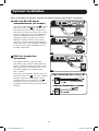
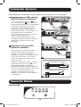
Optional Installation
These connections are optional. Your UPS will function properly without these connections.
1
USB and RS-232 Serial
Communications (all models)
Use the included USB cable (see
1A
) and/or
DB9 serial cable (see
1B
) to connect the
communication port on your computer to
the communication port of your UPS. Install
on your computer the Tripp Lite PowerAlert
Software appropriate to your computer’s
operating system. Your UPS may feature
additional communications ports; these
ports may also be connected to additional
computers which have PowerAlert Software
installed. Consult your PowerAlert manual
for more information.
2
EPO Port Connection
(all models)
This optional feature is only for those
applications which require connection to a
facility’s Emergency Power Off (EPO) circuit.
When the UPS is connected to this circuit,
it enables emergency shutdown of the
UPS’s inverter.
Using the cable provided, connect the EPO
port of your UPS (see
2A
) to a user-supplied
normally closed or normally open switch
according to the circuit diagram (see
2B
).
The EPO port is not a phone line surge
suppressor; do not connect a phone line to
this port.
13-12-130-93328A.indb 6 1/6/2014 2:59:23 PM

7
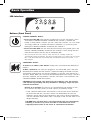
Basic Operation
LED Interface
“ON/OFF/STANDBY” Button
• To turn the UPS ON: with the UPS plugged into a live AC wall outlet*, press
and hold the “ON/OFF/STANDBY” button for one second.** Release the
button. If utility power is absent, you can “cold-start” the UPS (i.e.: turn it ON
and supply power for a limited time from its batteries***) by pressing and
holding the “ON/OFF/STANDBY” button for one second.**
• To turn the UPS OFF: with the UPS ON and receiving utility power, press and
hold the “ON/OFF/STANDBY” button for one second.** Then unplug the UPS
from the wall outlet. The UPS will be completely OFF.
* After you plug the UPS into a live AC outlet, the UPS (in ”Standby” mode) will
automatically charge its batteries, but will not supply power to its outlets until it is turned
ON. ** The alarm will beep once briefly after the indicated interval has passed. *** If
fully charged.
“MUTE/TEST” Button
To Silence (or “Mute”) UPS Alarms: briefly press and release the MUTE/TEST
button.*
To Run a Self-Test: with your UPS plugged in and turned ON, press and hold
the MUTE/TEST button for two seconds.* Continue holding the button until the
alarm beeps several times and the UPS performs a self test. See “Results of a
Self-Test” below. Note: you can leave connected equipment on during a self-test.
Your UPS, however, will not perform a self-test if the UPS is not turned on (see
“ON/OFF/STANDBY” Button description).
CAUTION! Do not unplug your UPS to test its batteries. This will remove
safe electrical grounding and may introduce a damaging surge into your
network connections.
Results of a Self-Test: The test will last approximately 10 seconds as the
UPS switches to battery to test its load capacity and battery charge.
• If the “OUTPUT LOAD LEVEL” LED remains lit red and the alarm continues
to sound after the test, the UPS’s outlets are overloaded. To clear the
overload, unplug some of your equipment and run the self-test repeatedly
until the “OUTPUT LOAD LEVEL” LED is no longer lit red and the alarm is no
longer sounding.
CAUTION! Any overload that is not corrected by the user immediately
following a self-test may cause the UPS to shut down and cease
supplying output power in the event of a blackout or brownout.
Buttons (Front Panel)
13-12-130-93328A.indb 7 1/6/2014 2:59:23 PM

8
Basic Operation continued
• If the “BATTERY WARNING” LED remains lit and the alarm continues to
sound after the test, the UPS batteries need to be recharged or replaced.
Allow the UPS to recharge continuously for 12 hours, and repeat the self-
test. If the LED remains lit, contact Tripp Lite for service. If your UPS
requires battery replacement, visit www.tripplite.com to locate the specific
Tripp Lite replacement battery for your UPS.
* The alarm will beep once briefly after the indicated interval has passed.
Indicator Lights (Front Panel)
All Indicator Light descriptions apply when the UPS is plugged into a wall outlet and turned ON.
“POWER” LED: this green LED lights continuously when the UPS is ON and
supplying connected equipment with AC power from a utility source. The LED
flashes and an alarm sounds (4 short beeps followed by a pause) to indicate
the UPS is operating from its internal batteries during a blackout or severe
brownout. If the blackout or severe brownout is prolonged, you should save files
and shut down your equipment since internal battery power will eventually be
depleted. See “BATTERY CHARGE” LED description below.
“VOLTAGE CORRECTION” LED: this green LED lights continuously whenever
the UPS is automatically correcting high or low AC voltage on the utility line
without the assistance of battery power. The UPS will also emit a slight clicking
noise. These are normal, automatic operations of the UPS, no action is required
on your part.
“OUTPUT LOAD LEVEL” LED: this multicolored LED indicates the approximate
electrical load of equipment connected to the UPS’s AC outlets. It will turn from
green (light load) to yellow (medium load) to red (overload). If the LED is red
(either illuminated continuously or flashing), clear the overload immediately by
unplugging some of your equipment from the outlets until the LED changes
from red to yellow (or green). CAUTION! Any overload that is not corrected by
the user immediately may cause the UPS to shut down and cease supplying
output power in the event of a blackout or brownout.
“BATTERY CHARGE” LED: when the UPS is operating from utility power, this
LED indicates the approximate charge state of the UPS’s internal batteries: red
indicates the batteries are beginning to charge; yellow indicates the batteries
are roughly midway through charging; and green indicates the batteries are fully
charged. When the UPS is operating from battery power during a blackout or
severe brownout, this LED indicates the approximate amount of energy
(ultimately affecting runtime) which the UPS’s batteries will provide: red
indicates a low level of energy; yellow indicates a medium level of energy; and
green indicates a high level of energy. Since the runtime performance of all UPS
batteries will gradually deplete over time, it is recommended that you
periodically perform a self-test (see MUTE/TEST Button description) to determine
the energy level of your UPS batteries BEFORE a blackout or severe brownout
occurs. During a prolonged blackout or severe brownout, you should save files
and shut down your equipment since battery power will eventually be depleted.
When the LED turns red and an alarm sounds continuously, it indicates the
UPS’s batteries are nearly out of power and UPS shut down is imminent.
“BATTERY WARNING” LED: this LED lights red and an alarm sounds
intermittently after you initiate a self test (See “MUTE/TEST” Button description)
to indicate the UPS batteries need to be recharged or replaced. Allow the UPS
to recharge continuously for 12 hours, and repeat the self-test. If the LED
continues to light, contact Tripp Lite for service. If your UPS requires battery
replacement, visit www.tripplite.com to locate the specific Tripp Lite replacement
battery for your UPS.
13-12-130-93328A.indb 8 1/6/2014 2:59:23 PM

9
NEMA 5-15R
Basic Operation continued
AC Receptacles: Your UPS features 15-amp AC outlets. These output
receptacles provide your connected equipment with AC line power during
normal operation and battery power during blackouts and brownouts. The UPS
protects equipment connected to these receptacles against damaging surges
and line noise. If you have a serial or USB connection to your UPS, you can
remotely reboot connected equipment by turning the receptacles OFF and ON
using Tripp Lite’s PowerAlert Software. Select models have their receptacles
divided into one or more load banks (labelled “LOAD 1,” etc.) which may be
remotely switched OFF and ON using Tripp Lite UPS software without
interrupting power to equipment connected to the other outlets. Select models
feature special outlets (clearly labeled on the rear panel) which provide surge-
only (not battery backup) protection designed for laser printers and other
heavy-draw devices. Select models also feature outlets labelled
“UNSWITCHED”, which may not be remotely switched off. See software
instructions for details.
Communications Ports (USB or RS-232): These ports connect your UPS to
any workstation or server. Use with Tripp Lite’s PowerAlert Software and
included cables to enable your computer to automatically save open files and
shut down equipment during a blackout. Also use PowerAlert Software to
monitor a wide variety of AC line power and UPS operating conditions. Consult
your PowerAlert Software manual or contact Tripp Lite Customer Support for
more information. See “USB and RS-232 Serial Communications” in the
“Optional Installation” section for installation instructions.
EPO (Emergency Power Off) Port: Your UPS features a EPO port that may be
used to connect the UPS to a contact closure switch to enable emergency
inverter shutdown. See Optional Installation.
Accessory Slot: Remove the small cover panel from this slot to install optional
accessories to remotely monitor and control your UPS. Refer to your
accessory’s manual for installation instructions. Contact Tripp Lite Customer
Support at (773) 869-1234 for more information, including a list of available
SNMP, network management and connectivity products.
Power Sensitivity Adjustment: This dial is normally set fully counter-
clockwise, which enables the UPS to provide maximum protection against
waveform distortions in its AC input. When such distortion occurs, the UPS will
normally switch to providing sine wave power from its battery reserves for as
long as the distortion is present. In areas with poor utility power or where the
UPS’s input power comes from a backup generator, chronic waveform distortion
could cause the UPS to switch to battery too frequently, draining its battery
reserves. You may be able to reduce how often your UPS switches to battery
due to moderate waveform distortion by experimenting with different settings
for this dial. As the dial is turned clockwise, the UPS becomes more tolerant of
variations in its input power’s AC waveform. NOTE: The further the dial is
adjusted clockwise, the greater the degree of waveform distortion the UPS will
allow to pass to connected equipment. When experimenting with different
settings for this dial, operate connected equipment in a safe test mode so that
the effect on the equipment of any waveform distortions in the UPS’s output
can be evaluated without disrupting critical operations.
Other UPS Features (Rear Panel)
13-12-130-93328A.indb 9 1/6/2014 2:59:23 PM

10
Input Breaker(s) (all models): Protect your electrical circuit from overcurrent
draw from the UPS load. If these breakers trip, remove some of the load, then
reset them by pressing the breaker(s) in.
Output Breaker (select models): Your UPS features one or more breakers that
protect your UPS from output overload. If one or more breakers trip, remove
some of the load on the circuit(s), then reset them by pressing the breaker
switch(es) in.
Ground Screw: Use this to connect any equipment that requires a chassis
ground.
Basic Operation continued
Storage and Service
Storage
Before storing your UPS, turn it completely OFF: with the UPS ON and receiving utility power, press
and hold the “ON/OFF/STANDBY” button for one second (an alarm will beep once briefly after the
interval has passed); then, unplug the UPS from the wall outlet. If you store your UPS for an
extended period of time, recharge the UPS batteries once every three months: plug the UPS into a
wall outlet; allow it to charge for 12 hours; and then unplug it and place it back in storage.
Note: after you plug the UPS in, it will automatically begin charging its batteries; however, it will not
supply power to its outlets (see Quick Installation section). If you leave your UPS batteries
discharged for an extended period of time, they will suffer a permanent loss of capacity.
Service
A variety of Extended Warranty and On-Site Service Programs are available from Tripp Lite. For
more information on service, visit www.tripplite.com/support. Before returning your product for
service, follow these steps:
1. Review the installation and operation procedures in this manual to insure that the service
problem does not originate from a misreading of the instructions.
2. If the problem continues, do not contact or return the product to the dealer. Instead, visit
www.tripplite.com/support.
3. If the problem requires service, visit www.tripplite.com/support and click the Product Returns
link. From here you can request a Returned Material Authorization (RMA) number, which is
required for service. This simple on-line form will ask for your unit’s model and serial numbers,
along with other general purchaser information. The RMA number, along with shipping
instructions will be emailed to you. Any damages (direct, indirect, special or consequential) to
the product incurred during shipment to Tripp Lite or an authorized Tripp Lite service center are
not covered under warranty. Products shipped to Tripp Lite or an authorized Tripp Lite service
center must have transportation charges prepaid. Mark the RMA number on the outside of the
package. If the product is within its warranty period, enclose a copy of your sales receipt.
Return the product for service using an insured carrier to the address given to you when you
request the RMA.
13-12-130-93328A.indb 10 1/6/2014 2:59:24 PM

11
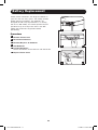
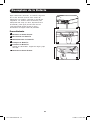
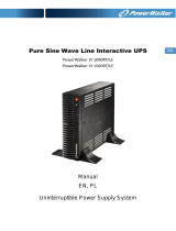
Battery Replacement
Under normal conditions, the original batteries in
your UPS will last many years. See Safety section
before replacing batteries. The batteries are
designed for hot-swap replacement (i.e. leaving
the UPS in ON mode), but some qualified service
personnel may wish to put the UPS in the OFF
mode and disconnect equipment before
proceeding.
Procedure
1
Remove Front Panel
2
Disconnect Batteries
3
Remove/Dispose of Batteries
4
Add Batteries
5
Connect Batteries
Attach connectors: black-to-black and red-to-red.
6
Replace Front Panel
1
6
2
5
3
4
13-12-130-93328A.indb 11 1/6/2014 2:59:24 PM

12
FCC RADIO/TV INTERFERENCE NOTICE: (FOR CLASS A MODELS)
Note: This equipment has been tested and found to comply with the limits for a Class A digital device, pursuant to Part 15 of the
FCC Rules. These limits are designed to provide reasonable protection against harmful interference when operated in a commercial
environment. This equipment generates, uses and can radiate radio frequency energy, and if not installed and used in accordance
with the instruction manual, may cause interference to radio communications. Operation of this equipment is likely to cause
harmful interference in which case the user will be required to correct the interference at his own expense. The user must use
shielded cables and connectors with this product. Any changes or modifications to this product not expressly approved by the party
responsible for compliance could void the user’s authority to operate the equipment.
FCC RADIO/TV INTERFERENCE NOTICE: (FOR CLASS B MODELS)
Note: This equipment has been tested and found to comply with the limits for a Class B digital device, pursuant to Part 15 of the
FCC Rules. These limits are designed to provide reasonable protection against harmful interference in a residential installation. This
equipment generates, uses and can radiate radio frequency energy, and if not installed and used in accordance with the instruction
manual, may cause interference to radio communications. However, there is no guarantee that interference will not occur in a
particular installation. If this equipment does cause harmful interference to radio or television reception, which can be determined
by turning the equipment off and on, the user is encouraged to try to correct the interference using one or more of the following
measures: reorient or relocate the receiving antenna; increase the separation between the equipment and the receiver; connect the
equipment into an outlet on a circuit different from that which the receiver is connected; consult the dealer or an experienced radio/
television technician for help. The user must use shielded cables and connectors with this product. Any changes or modifications to
this product not expressly approved by the party responsible for compliance could void the user’s authority to operate the
equipment. This device complies with part 15 of the FCC rules. Operation is subject to the following 2 conditions: (1) This device
may not cause harmful interference, and (2) This device must accept any interference received, including interference that may
cause undesired operation.
Regulatory Compliance Identification Numbers
For the purpose of regulatory compliance certifications and identification, your Tripp Lite product has been assigned a unique series
number. The series number can be found on the product nameplate label, along with all required approval markings and
information. When requesting compliance information for this product, always refer to the series number. The series number should
not be confused with the marking name or model number of the product.
UPS and Battery Recycling
Please recycle Tripp Lite Products. The batteries used in Tripp Lite products are sealed Lead-Acid batteries.
These batteries are highly recyclable. Please refer to your local codes for disposal requirements.
You can call Tripp Lite for recycling info at 1-773-869-1234.
You can go the Tripp Lite Website for up-to-date information on recycling the batteries or any Tripp Lite product.
Please follow this link: http://www.tripplite.com/en/support/recycling-program.cfm
Tripp Lite has a policy of continuous improvement. Product specifications are subject to change without notice.
Note on Labeling
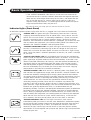
Two symbols are used on the label.
V~ : AC Voltage
V : DC Voltage
Warranty Registration
Visit www.tripplite.com/warranty today to register the warranty for your new Tripp Lite product.
You’ll be automatically entered into a drawing for a chance to win a FREE Tripp Lite product!*
* No purchase necessary. Void where prohibited. Some restrictions apply. See Web site for details.
1111 W. 35th Street, Chicago, IL 60609 USA • www.tripplite.com/support
13-12-130-93328A.indb 12 1/6/2014 2:59:25 PM

13
Manual del propietario
MÁS DE
1111 W. 35th Street, Chicago, IL 60609 USA • www.tripplite.com/support
Instrucciones Importantes de Seguridad
14
Instalación 16
Instalación Rápida 17
Instalación Opcional 18
Operación Básica 18
Almacenamiento y Servicio 22
Reemplazo de la Batería 23
Avisos 24
English 1
Français 25
SmartPro
®
para Instalación
de 1U en Rack
Sistemas UPS Inteligentes, Interactivos
Salida de 120V • 500VA – 1000VA
SMART500RT1U
Serie: AG-0097
SMART750RM1U
Serie: AGSM8269
SMART1000RM1U
Serie: AGSM5060
No es adecuado para aplicaciones móviles.
Copyright © 2014 Tripp Lite. Todos los derechos reservados.
SmartPro
®
es una marca registrada Tripp Lite.
13-12-130-93328A.indb 13 1/6/2014 2:59:26 PM
Page is loading ...
Page is loading ...
Page is loading ...
Page is loading ...
Page is loading ...
Page is loading ...
Page is loading ...
Page is loading ...
Page is loading ...
Page is loading ...
Page is loading ...
Page is loading ...
Page is loading ...
Page is loading ...
Page is loading ...
Page is loading ...
Page is loading ...
Page is loading ...
Page is loading ...
Page is loading ...
Page is loading ...
Page is loading ...
Page is loading ...
-
 1
1
-
 2
2
-
 3
3
-
 4
4
-
 5
5
-
 6
6
-
 7
7
-
 8
8
-
 9
9
-
 10
10
-
 11
11
-
 12
12
-
 13
13
-
 14
14
-
 15
15
-
 16
16
-
 17
17
-
 18
18
-
 19
19
-
 20
20
-
 21
21
-
 22
22
-
 23
23
-
 24
24
-
 25
25
-
 26
26
-
 27
27
-
 28
28
-
 29
29
-
 30
30
-
 31
31
-
 32
32
-
 33
33
-
 34
34
-
 35
35
-
 36
36


Tripp Lite SmartPro SMART500RT1U Owner's manual
- Type
- Owner's manual
Ask a question and I''ll find the answer in the document
Finding information in a document is now easier with AI
in other languages
Related papers
-
Tripp Lite BC Internet Owner's manual
-
-
-
-
Tripp-Lite SmartPro Series User manual
-
-
-
-
-
Other documents
-
 bXterra 350VA UPS BG350 Standby UPS Battery Backup, 6 Outlets, Easy Mute Button, RJ11, Energy Star, LEDs, Contoured Design, Compact User manual
-
Dynex DX-800U User manual
-
Legrand KEOR PDU Single Phase UPS User manual
-
Eaton BC36ML User guide
-
Belkin F6C700-EUR User manual
-
 Best Power Patriot Pro II 750 VA User guide
-
Middle Atlantic Products UPS-S1500R User manual
-
Lithonia Lighting LXRM Emergency Sign Installation guide
-
 PowerWalker VI 1500 RT LE Owner's manual
-


