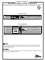
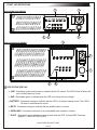
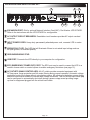
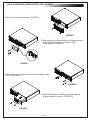
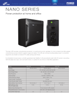
Middle Atlantic Products UPS-S1500R is a rackmount UPS that provides battery backup during power outages, automatic voltage regulation during periods of inconsistent utility power and surge protection. The UPS features a front panel LCD display that provides information on the UPS status, including input and output voltage, load level, and battery charge level. The UPS also has a variety of connectivity options, including USB, RS-232, and EPO (Emergency Power Off) ports. These ports allow the UPS to be monitored and controlled remotely.
Middle Atlantic Products UPS-S1500R is a rackmount UPS that provides battery backup during power outages, automatic voltage regulation during periods of inconsistent utility power and surge protection. The UPS features a front panel LCD display that provides information on the UPS status, including input and output voltage, load level, and battery charge level. The UPS also has a variety of connectivity options, including USB, RS-232, and EPO (Emergency Power Off) ports. These ports allow the UPS to be monitored and controlled remotely.


-
 1
1
-
 2
2
-
 3
3
-
 4
4
-
 5
5
-
 6
6
-
 7
7
-
 8
8
-
 9
9
-
 10
10
-
 11
11
-
 12
12
-
 13
13
-
 14
14
-
 15
15
-
 16
16
-
 17
17
-
 18
18
-
 19
19
-
 20
20


Middle Atlantic Products UPS-S1500R User manual
- Type
- User manual
- This manual is also suitable for
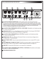
Middle Atlantic Products UPS-S1500R is a rackmount UPS that provides battery backup during power outages, automatic voltage regulation during periods of inconsistent utility power and surge protection. The UPS features a front panel LCD display that provides information on the UPS status, including input and output voltage, load level, and battery charge level. The UPS also has a variety of connectivity options, including USB, RS-232, and EPO (Emergency Power Off) ports. These ports allow the UPS to be monitored and controlled remotely.
Ask a question and I''ll find the answer in the document
Finding information in a document is now easier with AI
in other languages
Related papers
-
Middle Atlantic Products UPS-IPCARD Installation guide
-
-
-
Middle Atlantic Products 1000R Series User manual
-
Middle Atlantic Products MFR-RRK-12 Installation guide
-
-
-
-
-
Other documents
-
Manhattan Line Interactive User manual
-
Minuteman Endeavor ED1000RTXL2U User manual
-
Sprint S1000R User manual
-
-
Rosewill RU-103 User manual
-
 FSP/Fortron PPF4800305 Datasheet
-
Tripp Lite SmartOnline Rack/Tower UPS Owner's manual
-
Tripp-Lite SmartPro Series User manual
-
-
Tripp Lite SmartPro SMART1400RM2U Owner's manual
