Page is loading ...

1070224-2-B
1
CL CABINET INSTRUCTIONS
English/Français/Español
ONE DOOR CABINETS:
K-CB-CLC1526FS, K-CB-CLC1530AS,
K-CB-CLC2026FS, K-CB-CLC2030AS,
K-CB-CLC2030VAS, K-CB-CLC2031BAN,
K-3073
TWO DOOR CABINETS:
K-CB-CLC2526FS, K-CB-CLC3026FS,
K-CB-CLC3526FS

1070224-2-B
2
CL CABINET INSTRUCTIONS
General Notes
1. For recess mount see instructions below.
For surfaces mount instructions see page 2.
A surface mounted cabinet requires the optional
CLSK26 Mirror kit supplied with your cabinet.
2. If you have a K-CB-CLC1530AS or K-CB-CLC2030AS,
this is an arch cabinet.
3. If you have purchased the optional CLL Light
Kit refer to the instructions supplied with the light kit for
layout and wiring.
4.
Mounting location for
#8 x 1 1/2" philips
head screws
25 1/4" high
for CLC15 Models
d ls
24 1/4"W for CLC25 Models
29 1/4"W for CLC30 and CL
Models
4 1/4"W for CLC35 Models
35 1/4"W for CLC3626 Models
ROUGH OPENING DIMENSIONS
One Year Limited Warranty
Top View
Stud and wall
surface
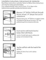
Install dome caps
over screws.
Cabinet flange fits
flush against wall.
Fig. 2
Install screws through
holes in cabinet as
shown in Fig. 1
DO NOT OVER-
TIGHTEN!
Use #8 x 1 1/2
Phillips head.
Fig. 1
ONE DOOR CABINETS: K-CB-CLC1526FS, K-CB-CLC1530AS, K-CB-CLC2026FS, K-CB-CLC2030AS
K-CB-CLC2030VAS, K-CB-CLC2031BAN, K-3073
TWO DOOR CABINETS: K-CB-CLC2526FS, K-CB-CLC3026FS, K-CB-CLC3526FS
Call our Customer Service Department - 1-800-4-KOHLER
(456-4537) from within the USA and Mexico, and
1-800-964-5590 from within Canada between 7:00 AM -
6:00 PM (Central Time) Monday to Friday if you have
any questions or require parts.
444 Highland Drive, Kohler, WI 53044, USA
1. Recessing the cabinet into the wall.
14 1/4"W for K-CB-CLC15 Model
19 1/4"W for K-
CB-CLC20 and
K-3073 Models
24 1/4"W for K-CB-CLC25 Model
29 1/4"W for K-CB-CLC30 Model
34 1/4"W for K-
CB-CLC35 Model
Mounting location for
#8 x 1 1/2" Philips
head screws
For the U.S.A. and Canada Only
KOHLER plumbing products are warranted to be free of defects in
material and workmanship for one year from date of installation.
Kohler Co. will, at its election, repair, replace or make appropriate
adjustment where Kohler Co. inspection discloses any such defects
occurring in normal usage within one (1) year after installation. Kohler
Co. is not responsible for removal or installation costs. Use of in-tank
toilet cleaners will void the warranty.
To obtain warranty service contact Kohler Co. either through your
Dealer, Plumbing Contractor, Home Center or E-tailer, or by writing
Kohler Co., Attn.: Customer Service Department, 444 Highland Drive,
Kohler, WI 53044, USA, or by calling 1-800-4-KOHLER from within the
USA, 1-800-964-5590 from within Canada and 001-877-680-1310 from
within Mexico.
Implied warranties including that of merchantability and fitness for
a particular purpose are expressly limited in duration to the duration
of this warranty. Kohler Co. and/or seller disclaims any liability for
special, incidental or consequential damages.
Some states/provinces do not allow limitations on how long an
implied warranty lasts, or the exclusion or limitation of special,
incidental or consequential damages so these limitations and exclusions
may not apply to you. This warranty gives you specific legal rights.
You may also have other rights which vary from state/province to
state/province.
This is Kohler Co.’s exclusive written warranty.
INSTALLER NOTE:
The K-CB-CLL03F ver
tical
fluorescent light changes the
width of the rough out. Please
refer to K-CB-CLL03F
instructions 1070228-2.

1070224-2-B
3
Cabinet bottom sits
in lip on bottom
mounting bar.
#8 x 2" Hex
head screw &
Wall anchor
(use 1/4" driver)
11" bottom mounting bar for K-CB-CLC15/20,
K-3073
21" bottom mounting bar for K-CB-CLC25
INSTALLER’S NO
TE:
Installing the cabinet on a wall without the door attached can make installing easier
for one person. Do not mount the doors until the box is in or on the wall.
Wall anchor
(if required)
Top mount clip
#8 x 2" Hex head screw
(Use 1/4" driver)
INSTALLER’S NO
TE:
2. Surface mounting the cabinet on a wall.
A. Install Mounting Bar.
(Step one varies on type of cabinet
you have, see below.)
Fig. 3A – For Single Door
Fig. 3B – For
Two Door
2. Drill 3/16” hole in wall for mounting bar anchors at locations
shown in Fig. 3. (If you do not use the anchor, drill a 3/32”
pilot hole.) After the holes are drilled, fit the mounting bar
onto the wall, refer to Fig. 3 for measurements, and Fig. 5
for information on anchor cinching.
B. Install
Top Clips
(Left and right top clips come connected, hold
both clips and snap them apart).
1. Fit cabinet into position on mounting bar as
shown in Fig. 4A.
2. Place clip in position as shown in Fig. 4B and
mark with a pencil. Remove clip and cabinet and
drill the pilot or anchor holes where marked.
3. Fix both the clips into position with a screw, and
slide the clip into the up position. Sit the cabinet
on the mounting bar, then lower and tighten the
screws into place, as shown in Fig. 4C
.
4. See Fig. 5 on next page for proper turns required
for anchor cinching.
5. See page 4 for Side Kit Mirror application.
Fig. 4A
3/4"
4 1/2" from edge
Bottom of Cabinet
2" from edge
K-CB-CLC20
and K3073
K- CB-CLC15
1. Drill two 3/16 holes in bottom mounting bar at indent
location. Use the supplied anchors or locate studs
if possible.
Side of Cabinet
3/4"
Bottom of Cabinet
2" from edge
1. Drill three 3/16 holes in bottom mounting bar at indent
location. Use the supplied anchors or locate studs
if possible.
Side of Cabinet
If you are using a CLL Top Light
STOP HERE and follow the CLL instructions.
31" bottom mounting bar for K-CB-CLC35
26" bottom mounting bar for K-CB-CLC30

1070224-2-B
4
3. Attaching Side Kits to a Surface Mounted Cabinet
Fig. 4B & 4C
4B
4C
Fig. 5
Once Screw is bottomed out on
mount clip, turn screw an additional
5 to 7 turns to fully expand the anchor.
Side view at top of cabinet
1. Apply foam tape to Side kit bracket.
A. Peel tape from sheet, leave liner on.
B. Apply as shown to side kit brackets,
be sure they are clean and dry.
C. DO NOT PEEL RELEASE LINER
UNTIL YOU HAVE TEST FIT THE
SIDE KITS ON THE CABINET!
2. Attach the side kit brackets to the
cabinet as shown in Fig. 6.
3. Test fit the side kit , then clean the
back of the side kits with rubbing alcohol.
4. Peel the release tape from the
brackets and apply the side kits, push
fir mly to set.
5. Cover the screw heads with the screw caps.
Align top of side kit with top of flange.
Side kit bracket
(Fits tight under the
flange of cabinet)
#8 x 3/8" screws
self thread into
Side Kit brackets
Side Kit brackets
2 pieces
26" high
Fig. 6

1070224-2-B
5
2. Door adjustments
8-32 x 1/2"
6-32 x 3/8"
A
B
B
A. This screw releases the door from the cabinet and
allows up and down adjustment. Fig. 9
B. These screws allow you to plumb the door as
shown in Fig. 10.
C. The screws you use for attaching the hinges.
(Supplied with hinges)
4. Installing the shelves – see Fig. 11
1. Push/twist the pins
into place.
A. Push one side of
the shelf into the
left or right clips.
B. Snap the shelf
down into the
opposite side. If
the shelf is too
tight, repeat the
process from the
other side.
2. Fill the remaining
holes with the plugs.
Fig. 11
Fig. 9
Fig. 10
1. Installing the door bumpers – see Fig. 9
1.
Install the clear door bumpers in the round indent
area at the top and bottom of the door.
Fig. 9
BELOW FOR 1 & 2 DOOR CABINET ONLY
A
B
1
2
Door
Bumper

1070224-2-B
6
#8" X 3/8" Side Kits Screws
#8 X 1 1/2" Phillips
Head Screws
CB-3115X26 Side Mirrors
4 Side Kits brackets
Wall Anchors
ves (SHLFCLC25,
CB-SHLFCLC30, CB-SHLFCLC35)
(Doors shipped loose are supplied with
this hinge kit)
(CB-RO332100W)
26" Mounting Bar for K-CB-CLC3026
(CB-RO332600W)
31" Mounting Bar for K-CB-CLC3526
(CB-RO333100W)
Toothbrush covers for 10” door
Door Bumpers
2 Glass Shelves
(CB-SHLFCLC15 - K-CB-CLC15)
(Doors shipped loose are supplied with
this hinge kit)
21” Mounting Bar for
K-CB-CLC1526 & K-CB-CLC2026 , K-3073
CB-120331100M
Toothbrush covers for 10” door
Door Bumpers
Screw Caps
#8 X 2" Hex Head Slotted Screws
4 Side Kits Bracket Foam tape
Top Clips
Snap-in Pins
Checklist • Care & Maintenance
Parts supplied with your cabinet. (For cabinet body and door replacement, call customer service with
model number.) Be sure to check the cardboard supports in the carton, glass parts are packed in them.
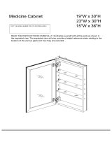
A. The cabinet door and interior are constructed of mirror and aluminum. Use only a damp cloth to
clean. Spray the cloth, not the mirror when cleaning. Mirrors are damaged by the use of ammonia
or vinegar based cleaners. Rubbing alcohol can be used for stubborn stains.
B. Do not use abrasive cleansers on any part of the cabinet.
Hole plugs
21" Mounting Bar for K-CB-CLC2526
2 Glass Shelves
(CB-SHLFCLC25,
21" Mounting Bar for
2 Glass Shelves
(CB-SHLFCLC20 - K-CB-CLC20 &
K-3073)
(2) CB-BAGCLCHGE Hinge Kit
(1) CB-BAGCLCHGE Hinge Kit
1. Cleaning
Parts on the left are used with all cabinets
Parts on left are used with all cabinets.
ONE DOOR CABINET – Part LIst
TWO DOOR CABINET – Part List

Experience Gracious Living @
www. .com
A. This scre
w releases the door f
ws up and down adjustment. Fig. 9
The scre ou use for attaching the hinges
(Supplied with hinges)
Installing the shelves – see Fig.
/