Legrand Correlated Color Temperature Low Voltage Timer Switch (Tri-Lingual) Installation guide
- Type
- Installation guide

Wattstopper
®
Correlated Color Temperature Low Voltage Timer Switch
Interrupteur faible tension pour la programmation de la température
de couleur corrélée
Interruptor con temporizador de bajo voltaje de Temperatura de
color correlacionada
Quick Start Guide • Guide de démarrage rapide • Guía de inicio rápido
No: 25090 – 08/17 rev. 3
Catalog Numbers • Les Numéros de Catalogue • Los Números de Catálogo:
Country of Origin: Made in China • Pays d’origine: Fabriqué en Chine • País de origen: Hecho en China
SPECIFICATIONS
Voltage .............................................................................. 24VDC
Current Consumption ...........................................................12mA
Power Supply ................................. Wattstopper Room Controller
Connection to the DLM Local Network .................... 2 RJ-45 ports
DLM Local Network characteristics when using LMRC-11x/2xx
room controllers:
Low voltage power provided over Cat 5e cable (LMRJ);
max current 800mA. Supports up to 64 load addresses,
48 communicating devices including up to 4 LMRC-10x
series and/or LMPL-101 controllers.
Free topology up to 1,000’ max.
Environment ................................................. For Indoor Use Only
Operating Temperature .................32° to 131°F (0° to 55°C)
Storage Temperature ...................23° to 176°F (-5° to 80°C)
Relative Humidity .......................5 to 95% (non condensing)
Patent Pending
This unit is pre-set for Plug n’ Go™ operation,
adjustment is optional.
For full operational details, adjustment and more features
of the product, see the DLM System Installation Guide
provided with Wattstopper room controllers, and also
available at www.legrand.us/wattstopper.
Installation shall be in accordance with all applicable
regulations, local and NEC codes. Wire connections
shall be rated suitable for the wire size (lead and building
wiring) employed.
For Class 2 DLM devices and device wiring: To be
connected to a Class 2 power source only. Do not reclassify
and install as Class 1, or Power and Lighting Wiring.
Do not apply cleaning solvent directly onto unit. Apply
cleaning solvent onto a cloth, then wipe the unit to clean it..
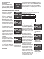
DESCRIPTION AND OPERATION
The LMTS-101-CCT provides daily control of Correlated Color Temperature (CCT) lighting fixtures of any CCT device within a single
DLM Network. Two types of event scheduling are available to control CCT:
Astro CCT event scheduling uses a location based Astronomical Clock entry, which determines Sunrise and Sunset times. A restricted
set of parameters allows the LMTS-101-CCT to make seasonal adjustments based on the astronomical settings. In Astro CCT mode,
only the CCT Target Level parameter can be modified.
Custom CCT event scheduling allows editing the default parameters for each event, including Start Time, Stop Time and a Target CCT Level.
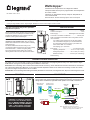
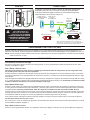
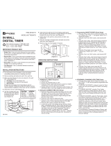
MOUNTING
LMRJ Cables
LMSW-105-CCT
Preset Switch
Occupancy
Sensor
LMTS-101-CCT
Schedule Switch
Daylighting Sensor
LMFC-RJ
DLM Cable Connector
LMLM-101 Mounted on
Araya or Blanco Logic Module
LMPB-100
Power
Booster
J-Box
120/277VAC
NOTE: Each DLM local network must include a
DLM room controller, relay panel, or power booster
to supply low voltage power to the LMLM-101.
Red
Black
Blue
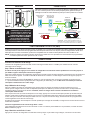
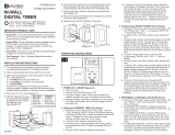
CONNECTIVITY
The illustration below shows an examples of free-topology wiring. The LMTS-101-CCT
communicates with all other Digital Lighting Management devices connected to the low
voltage DLM Local Network, regardless of their position on the DLM Local Network.
CAUTION: TO CONNECT A COMPUTER
TO THE DLM LOCAL NETWORK USE THE
LMCI-100. NEVER CONNECT THE DLM
LOCAL NETWORK TO AN ETHERNET
PORT – IT MAY DAMAGE COMPUTERS
AND OTHER CONNECTED EQUIPMENT.

2
PLUG N’ GO OPERATION (PNG)
All loads in the local DLM network that are CCT compatible will automatically respond to schedule events in the LMTS-101-CCT.
Additionally, all loads in the local DLM network will respond to the On/Off button whether or not they are CCT compatible.
NOTE: Only loads bound to the LMTS-101-CCT button will respond to the schedule events. See the following section on Push ‘n Learn.
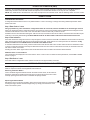
PUSH N’ LEARN
Load Selection Procedure
A configuration button allows access to our patented Push n’ Learn™ technology to change the binding relationship between switch
buttons and loads.
Step 1 Enter Push n’ Learn
Using a pointed tool, press and hold the configuration button for 3 seconds, until the Red LED on the switch begins to blink.
When you release the switch’s configuration button, the red LED on other communicating DLM Local Network devices begins to blink.
The DLM Local Network is now in PnL mode. The Red LEDs continue to blink until you exit PnL mode.
All loads in the room turn OFF after entering PnL. After one second, one load turns ON. This is Load #1, which is bound to the button as part
of the Plug n’ Go factory default setting. The Blue LED will be ON for all switch buttons and sensors that are bound to this load.
Step 2 Load selection
Press and release the configuration button to step through the loads connected to the DLM Local Network. As each load turns ON note
which devices (switch buttons and sensors) are showing the blue LED. These devices are currently bound to the load that is ON. By
default, all loads in the local DLM network are bound to the LMTS-101-CCT.
To unbind a switch button from a load, press the switch button while its blue LED is ON. The blue LED turns OFF to indicate the button
no longer controls the load that is currently ON. Note that if LMTS-101-CCT button is unbound from the load, the schedule events will
also have no effect on that load.
Pressing the switch button again while the load is ON rebinds the load to the button and the blue LED illuminates.
Additional Push ‘n Learn Features
Three parameters are displayed in the screen while in Push ‘n Learn mode. For details on these parameters, see the Push ‘n Learn
section on page 4.
Step 3 Exit Push n’ Learn
Press and hold the configuration button until the red LED turns off, approximately 3 seconds.
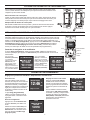
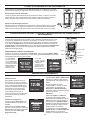
ACCESSING PROGRAMMING PARAMETERS
To access programmable parameters directly on the LMTS-101-CCT, remove the switch
button to expose the Select and navigational buttons behind it.
Removing the Switch Button
Insert a small flat edged screwdriver between the button and the frame, at the bottom of
the button. Rotate the screwdriver downward so that it catches the channel in the button
and keep pressing down till the button is released and springs forward.
Replacing the Switch Button
Reinsert the lens in the proper orientation: place the two posts at the top of the button at
a 30 degree angle, with the chamfered edge facing up. Gently press the bottom of the
button until it locks in place.

3
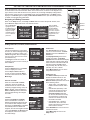
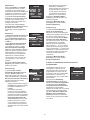
SETTING THE TIME AND DATE AND MODIFYING PROGRAMMING PARAMETERS
When the LMTS-101-CCT is powered up, it will first display a boot up screen showing the version
of the firmware in the unit and will then switch to the Home screen, as shown in the diagram to the
right. However, if the date and time have not yet been set, a message will display stating that the
date and time need to be set. To enter Setup mode, press the Select button. The Setup screen
displays. Press Select again to display the Set Time and Date screen. (See the following section
for detail on all programming parameters.
Navigating and Editing Parameters
When on the Setup screen, use the Up and Down buttons to select the specific function, then
press Select to display that screen. For all other screens:
ON/OFF
CONFIG
SELECT
DOW
N
UP
DST
Mon 08/14/2016
12:46
Prog 1 2 3 4 5 6
10
PM
SET TIME AND DATE
PREVIOUS MENU
TIME:
DATE:
DST:
START:
END:
06 : 30 AM
08/14/16
DISABLE
2nd Sun Mar
1st Sun Nov
SET TIME AND DATE
PREVIOUS MENU
TIME:
DATE:
DST:
START:
END:
06 : 30 AM
08/14/16
DISABLE
2nd Sun Mar
1st Sun Nov
With the Parameter
highlighted, press
the Select button to
toggle to the Value,
OR press the Up
or Down buttons to
move to a different
parameter.
With the Value
highlighted, press
the Up or Down
buttons to change
the value, OR press
the Select button to
toggle back to the
Parameter.
PROGRAMMABLE PARAMETERS
Setting Date/Time, Location, and Preferences
DST
Mon 08/14/2016
12:46
Prog 1 2 3 4 5 6
10
PM
SETUP
SET TIME AND DATE
LOCATION
PREFERENCES
SCHEDULING
MAIN PAGE
Home Screen
This screen displays the current date
and time, as well as if Daylight Savings
Time (DST is currently in effect). The
AM/PM designation does not display if
the unit is set to show a 24 hour clock
(see Preferences.)
The Prog line shows the number of
scheduling events. The one currently in
effect will blink.
Setup Screen
Press the Select button on the Home
screen to display this screen.
Use the Up and Down buttons to
choose an option and press Select.
To return to the Home screen, select
Main Page
SET TIME AND DATE
PREVIOUS MENU
TIME:
DATE:
DST:
START:
END:
06 : 30 AM
08/14/16
DISABLE
2nd Sun Mar
1st Sun Nov
Set Time and Date
Enter the current Time and Date.
These are used by Schedules to
determine when an event is active.
If following Daylight Savings Time, set
DST to “Enable”. When enabled, the
Start and End parameters determine
when Daylight Savings Time begins
and ends.
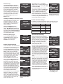
LOCATION
PREVIOUS MENU
LONGITUDE:
LONGITUDE:
TIME ZONE:
-086°
+33°
-06
<Sunrise: 05:39>
<Sunset: 19:02>
Location
Enter the Longitude and Latitude
of the current location. A number of
latitude and longitude lookup tools exist
on the Internet. One example is www.
latlong.net. The Time Zone is calculated
automatically based on latitude and
longitude, but can be changed if needed.
The current Sunrise and Sunset times
are displayed, based on the location
and date settings.
PREFERENCES
MORE OPTIONS
TIME FMT:
DATE FMT:
DIS INTENSITY:
DIS TIMEOUT:
12 HOURS
MM/DD/YY
90%
NEVER
Preferences
The Time Format can be set to a
12 hour or 24 hour format. The Date
Format can be set to MM/DD/YY or
DD-MM-YY.
The Display Intensity can be set to
a range of 10-100%. The Display
Timeout determines whether the display
will shut off after a period of time during
which no button on the LMTS-100-CCT
has been pressed. Available values:
10s (seconds), 20s, 30s, 40s, 50s, 1m
(minutes), 5m, 10m, or Never.
Select More Options to move to the
next preferences screen
PREFERENCES
NEXT MENU
MAIN PAGE
Btn LOCKOUT:
Btn FUNCTION:
OFF
TOGGLE LOAD
Preferences (2)
The Button Lockout parameter will
disable the ON/OFF button on the
LMTS-100-CCT if set to “ON”. The
Button Function parameter can be set
to the following values:
• Toggle Load – Turns all bound
loads in the DLM network ON or
OFF.
• Override Sch (Schedule) – Will
override all schedule events for
a period of time based on the
Override Duration parameter
(on the next Preferences screen).
Once the button is pressed, the
override can’t be turned off until
the duration is ended.
• Override/Resume – Similar to
Override Sch, but in this case,
pressing the button a second time
will turn off the override.
Select Next Menu to move to the next
Preferences screen.
Select Main Page to return to the
Setup screen.

4
PREFERENCES
MAIN PAGE
OVERRIDE DURATION:
1 HOUR
Preferences (3)
The Override Duration parameter
determines how long a schedule event
is overridden, after the On/Off button is
pressed (when the Button Function
is set to Override Sch or Override/
Resume). Available values: 1,2, 3, or
4 hours, All Day (ends when Event 1
occurs the next day), or Next Sched
(ends when the next event occurs)
Select Main Page to return to the
Setup screen.
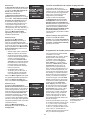
Creating or Modifying Schedule Events
SCHEDULING
NEW EVENT LIST
EDIT CURRENT EVENT
LIST
The LMTS-100-CCT stores only one
schedule in memory at a time. A
schedule consists of 6 events for an
Astro schedule or 2-8 events for a
Custom schedule.
When the Scheduling screen is
selected from Setup, there are two
options. New Event List will delete the
current schedule and start new schedule
from default values. Edit Current Event
List will display current events and allow
you to modify those values.
SCHEDULING
EVENT(S) TYPE
ASTRO
CUSTOM
Scheduling Event(s) Type
If you select New Event List on
the Scheduling screen, this screen
appears. Select either Astro or
Custom for the event type.
SCHEDULING
NEXT
EVENT:
TARGET CCT:
START:
FINISH:
#1
2000K
12:00 AM
06:00 AM
SCHEDULING
PREV NEXT
EVENT:
TARGET CCT:
START:
FINISH:
#2
5500K
06:00 AM
09:00 PM
Custom Event Scheduling
Custom Schedules start with a default
of 5 events. You can add up to 3 more
for a total of 8. For each event you
select the Target CCT level, and then
select specific times for the Start and
Finish of that event. As with Astro
scheduling, the finish time of one event
can’t overlap with the start time of the
next event. However, a gap of time can
occur between the end of one even
and the start of the next event.
When the Start time occurs, the CCT
value of the load will begin gradually
changing from the Target CCT value of
the previous event to the value of the
current event. It will reach the new value
at the Finish time. Therefore, the longer
the amount of time between start and
finish, the more gradual the change. If
there is a gap of time between the finish
of one event and the start of the next
event, the CCT level will remain the
same during that period of time.
All events must occur in a time frame
between 12:00 AM and 11:59 PM.
However, you do not have to start
event 1 at 12:00AM and end the last
event at 11:59 PM. There can be a gap
of time between the end of one day
and the start of the next.
Event 5 screen initial
default
SCHEDULING
PREV DONE
EVENT:
TARGET CCT:
START:
FINISH:
#5
2000K
07:00 PM
11:59 PM
After editing Event 1, select Next to
display Event 2. Continue editing events,
until you reach event 5. At this point, Next
is replaced by Done.
If you edit the Finish time so that it
occurs before 11:59 PM, the Add option
appears, allowing you to add another
event. The Start and Finish times
of the new event are set to the same
time as the Finish time of the previous
event. You can keep adding events, up
to 8 total, as long as the Finish time is
set to a value less than 11:59PM
SCHEDULING
PREV ADD DONE
EVENT:
TARGET CCT:
START:
FINISH:
#5
2000K
07:00 PM
11:00 PM
Event 5 screen after
changing Finish time so
it ends before 11:59 PM
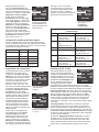
Astro Event Scheduling
SCHEDULING
NEXT
EVENT:
TARGET CCT:
START:
FINISH:
(ASTRO) #1
35%
Sunrise+00
Sunrise+30
SCHEDULING
PREV NEXT
EVENT:
TARGET CCT:
START:
FINISH:
(ASTRO) #2
65%
Sunrise+30
MORNING
SCHEDULING
PREV DONE
EVENT:
TARGET CCT:
START:
FINISH:
(ASTRO) #6
10%
Sunset+45
Sunset+75
Astro Schedules have 6 predefined
events. For each event, set the Target
CCT level. The level is a percentage
of CCT defined by the min/max range.
By default, the six Events progress
through the following values from
sunrise through Nightime: 35%, 65%,
100%, 65%, 35%, 10%
The six events are pre-programmed to
specific general categories of the day for
the Start and Finish of the event. These
categories can’t be changed. However,
for the Events that occur around Sunrise
or Sunset, you can modify the number
of minutes plus or minus the sunrise/
sunset time for that event to begin or
end. The range and default event values
are shown in the chart on the following
page.
As with Custom scheduling, the Target
CCT value will gradually change from
the value of the previous event to the
value of the current event, based on
the Start and Finish values.Events
cannot overlap. You can, however,
have a gap in time, as in the default
values of Events 5 and 6. If there is a
gap of time between the finish of one
event and the start of the next event, the
CCT level will remain the same during
that period of time.
... and so on through
events 3, 4, 5, and 6.
Select Next to
display Event 2
Select Done to return
to the Setup screen.
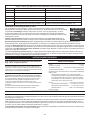
Default Schedule Settings
By default, out of the box and after a reset, the LMTS-101 is set
to use Custom Event Schedule, with five events, set as follows:
Target CCT Start Finish
2000K 12:00 AM 6:00 AM
5500K 6:00 AM 9:00 AM
5500K 9:00 AM 5:00 PM
2000K 5:00 PM 7:00 PM
2000K 7:00 PM 11:59 PM

5
Astro Event Start/Finish Ranges and Defaults
Event Start Finish
1 Sunrise (-90 to +10 min) Default: 0 Sunrise (+10 to +30 min) Default: +30
2 Sunrise (+30 to +90 min) Default: +30 Morning
3 Morning Mid-Day
4 Evening Sunset (-90 to -30 min) Default: -60
5 Sunset (-30 to 0 min) Default: -15 Sunset (0 to +30 min)
Default: +15
6 Sunset (+30 to +60 min) Default: +45 Sunset (+60 to +90 min) Default: +75
Push ‘n Learn Parameters
This screen displays in Push n’ Learn mode. These parameters do not necessarily apply specifically to the
LMTS, but instead to the function on various components in the DLM network.
The Load parameter indicates the currently active load being programmed. This will change automatically if
the Config button on any device in the DLM network, or the load button on the fixture controller is pressed.
You can also manually change it in the display.
Operation determines the operating mode If set to Manual, a DLM switch is required to turn on a load.
(This includes the LMTS-100-CCT if Button Function is set to Toggle.) A sensor is then used to keep the
load ON, based on occupancy. If set to Auto, either a switch or occupancy sensor can turn a load ON.
If Blink is turned ON, the LED on a switch will flash to provide a visual warning before the load is turned OFF by a sensor registering
vacancy. For the LMTS-100-CCT, the LED will only blink if the Button Function is set to Toggle. The button LED will not blink if it is set
to an override function.
The Daylighting parameter does not apply to the LMTS-100-CCT, but instead to the DLM Network. It determines if the load will respond
to commands from a daylight sensor. By default, daylight is enabled for load 1 and disabled for all other loads.
LOAD CONFIGURATION
(Push n Learn)
EXIT PNL
LOAD:
OPERATION:
BLINK:
DAYLIGHTING:
01
Manual
OFF
OFF
INSTRUCTIONS EN FRANÇAIS
SPÉCIFICATIONS
Tension .................................................................................. 24 VCC
Consommation de courant ........................................................12mA
Alimentation électrique .................... Wattstopper contrôleur de pièce
Connexion au réseau local DLM .................................. 2 ports RJ-45
Caractéristiques du réseau local DLM pendant l’utilisation de
LMRC-111/112:
La basse tension est générée par le câble Cat 5e (LMRJ);
courant maximal 800mA. Supporte jusqu’à 64 adresses de
charge, 48 dispositifs de communication incluant jusqu’à 4
séries LMRC-10x et contrôleurs LMPL-101. Topologie libre
allant jusqu’à 305 m (1 000 pi) max.
Environnement .................................Pour usage intérieur seulement
Température de fonctionnement ........0 ° à 55°C (32 ° à 131°F)
Température d’entreposage ............-5 ° à 80 °C (23 ° à 176 °F)
Humidité relative ..............................5 à 95 % (non condensée)
Brevet en instance
Cet appareil est préréglé pour un fonctionnement Plug n’ Go
MC
et son réglage est optionnel.
Pour connaître tous les détails opérationnels, les réglages et les fonctions
supplémentaires du produit, consulter le guide d’installation du système
DLM fourni avec Wattstopper contrôleurs de pièce et aussi disponible au
www.legrand.us/wattstopper.
L’installation doit être effectuée conformément à tous les règlements
ainsi qu’aux codes locaux et de la NEC en vigueur. Les raccordements
de fils doivent être classés comme pouvant convenir au calibre du fil (fil de
sortie et de bâtiment) utilisé.
Pour les dispositifs DLM de classe 2 et le câblage du dispositif : Doit être
connecté à une source d’alimentation de classe 2 seulement. Ne pas
reclasser et installer en tant que classe 1 ou en tant que fil d’alimentation ou
d’éclairage.
Ne pas appliquer de solvant de nettoyage directement sur l’appareil. Appliquer
le solvant de nettoyage sur un chiffon et frotter l’appareil pour le nettoyer.
DESCRIPTION ET FONCTIONNEMENT
L’interrupteur LMTS-101-CCT permet le contrôle quotidien des appareils d’éclairage à température de couleur corrélée faisant partie de
n’importe quel dispositif à température de couleur corrélée au sein d’un réseau local DLM unique. Deux types de programmation des
événements sont offerts pour contrôler la température de couleur corrélée :
La programmation d’événement Astro CCT (TCC astronomique) utilise les entrées d’une horloge astronomique, laquelle détermine
les heures du lever et du coucher du soleil. Un ensemble restreint de paramètres permet à l’interrupteur LMTS-101-CCT d’apporter
des ajustements saisonniers en fonction des réglages astronomiques. Les réglages par défaut sont générés en fonction du nombre
d’événements choisi. En mode Astro CCT (TCC astronomique), seul le paramètre Target CCT (TCC cible) peut être modifié
La programmation d’événement Custom CCT (TCC personnalisée) permet de modifier les paramètres par défaut pour chaque
événement, notamment Start Time (Heure de début), Stop Time (Heure de fin) et Target CCT Level (niveau de TCC cible).
Page is loading ...
Page is loading ...
Page is loading ...
Page is loading ...
Page is loading ...
Page is loading ...
Page is loading ...
Page is loading ...
Page is loading ...

800.879.8585
www.legrand.us/wattstopper
No. 25090 – 08/17 rev. 3
© Copyright 2017 Legrand All Rights Reserved.
© Copyright 2017 Tous droits réservés Legrand.
© Copyright 2017 Legrand Todos los derechos reservados.
Wattstopper warranties its products to be free
of defects in materials and workmanship for a
period of five (5) years. There are no obligations
or liabilities on the part of Wattstopper for
consequential damages arising out of, or in
connection with, the use or performance of this
product or other indirect damages with respect
to loss of property, revenue or profit, or cost of
removal, installation or reinstallation.
Wattstopper garantit que ses produits sont
exempts de défauts de matériaux et de fabrication
pour une période de cinq (5) ans. Wattstopper
ne peut être tenu responsable de tout dommage
consécutif causé par ou lié à l’utilisation ou
à la performance de ce produit ou tout autre
dommage indirect lié à la perte de propriété, de
revenus, ou de profits, ou aux coûts d’enlèvement,
d’installation ou de réinstallation.
Wattstopper garantiza que sus productos
están libres de defectos en materiales y mano
de obra por un período de cinco (5) años. No
existen obligaciones ni responsabilidades por
parte de Wattstopper por daños consecuentes
que se deriven o estén relacionados con el
uso o el rendimiento de este producto u otros
daños indirectos con respecto a la pérdida
de propiedad, renta o ganancias, o al costo
de extracción, instalación o reinstalación.
WARRANTY INFORMATION INFORMATIONS RELATIVES À LA GARANTIE INFORMACIÓN DE LA GARANTÍA
-
 1
1
-
 2
2
-
 3
3
-
 4
4
-
 5
5
-
 6
6
-
 7
7
-
 8
8
-
 9
9
-
 10
10
-
 11
11
-
 12
12
-
 13
13
-
 14
14
-
 15
15


Legrand Correlated Color Temperature Low Voltage Timer Switch (Tri-Lingual) Installation guide
- Type
- Installation guide
Ask a question and I''ll find the answer in the document
Finding information in a document is now easier with AI
in other languages
Related papers
-
Legrand Digital Lighting Management Low Voltage CCT Controller (Tri-Lingual) Installation guide
-
-
Legrand Wattstopper LMPL-101 Quick start guide
-
wattstopper LMSW-101/102/103/104/108 DLM Low Voltage Switches Quick Start Quick start guide
-
-
-
-
-
-
Other documents
-
wattstopper LMSW-105-CCT Installation guide
-
Robus RDR6D2W-11 Product information
-
wattstopper LMRC-101 Quick start guide
-
-
Intermatic DT121K Installation guide
-
-
 Utilitech UTTNDIW7D Operating instructions
-
 Utilitech UTDT9IW7 Quick Use Manual
-
Tork RZ307 User guide
-
 BN-LINK BND-60 SU135A Owner's manual


