
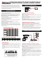
Power Supply Voltage Power Supply Voltage 12 VDC12 VDC 24 VAC24 VAC 28 VAC28 VAC
Voltage at the camera
100 mA Camera
Dual 24 AWG
Dual 22 AWG
300 mA Camera
1 Amp Camera
11.5 VDC 21 VAC 21 VAC
Dual 24 AWG
Dual 22 AWG
Dual 24 AWG
Dual 22 AWG
175 ft 1,000 ft 2,500 ft
300 ft
50 ft
1,500 ft 4,000 ft
850 ft350 ft
100 ft 600 ft 1,400 ft
15 ft 100 ft 250 ft
30 ft 150 ft 400 ft
Power Distance Chart
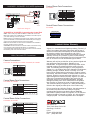
Application Diagram
The Vigitron VPD series are designed to combine video, PTZ data, and
camera power over a single 4-pair UTP cable to simplify CCTV instalations in
a structured wiring environment. They support up to 16 cameras. These units
receive low-voltage camera power from any third-party multi-output Class 2
power supply. Each camera power output (excluding Vi1053) is equipped with
a self-resetting fuse for extra protection.
DVR
1053VPD
1053VPD
1053VPD
Vi1316VPD; 16-Ch VPD Combiner
Cat-5
Cat-5
Data
Data
Data
Data
Power
Power
One Cat5 Cable
per 4 video feeds
Local Power
24/28VAC PS
for Cameras
Cat-5
Vi6016HR
16-Ch. Active Receiver
16 Coax Jumpers
1053VPD
1053VPD
1053VPD
1053VPD
Data
Power
24/28VAC PS
for Cameras
1053VPD
Data
1053VPD
1053VPD
DVR
Cat-5
1. Use point-to-point Unshielded Twisted Pair wire, 24-16 AWG (0,5-1,3mm),
stranded or solid, Category 2 or better.
2. The Video signal may co-exist in the same wire bundle as other Video,
telephone, Data, control signals, or low-voltage Power. It is also OK to run
Vigitron Video signals in or near electromagnetic fields (in accordance with
National Electrical Code, local, or other local safety requirements).
3. Measure the wire distance.
4. DO NOT USE SHIELDED TWISTED PAIR WIRE. Multi-pair (6 pair or
more) wires with an overall shield are fine.
5. DO NOT USE UN-TWISTED WIRE.
6. DO NOT place a transmit and a receive signal in the same wire bundle. It
may cause interference.
7. DO NOT send “Up-the-Coax” Pan/Tilt/Zoom signals through active
(amplified) Vigitron transmitters or receivers.
Passive Vigitron transceivers can transmit “Up-the-Coax” P/T/Z control
signals up to 750ft (225m).
8. Vigitron recommends the use of 18AWG solid wires for power connections.
Verify wire distance, camera current requirement and wire resistance limit for
the maximum distance that Power can travel. Use “Power Distance Chart” to
verify the wire distance.
Safety Warnings
- This installation should be made by a qualified service person and should
conform to all local codes.
- Never put Vigitron signals in the same conduit as high-voltage wiring.
- To reduce a risk of fire or electrical shock, do not expose this product to rain
or moisture.
- The Vigitron equipment shall not be exposed to dripping or splashing.
- No objects filled with liquids, such as vases, shall be placed on Vigitron
equipment.
AWG 24AW G 22AW G 20AW G 19AW G 18AW G 16AW G
mm 0,5mm 0,6mm 0,7mm 0,8mm 1,0mm 1,3mm
Ohm 52 32 20 16 13 8.2
Loop Resistance per 1,000ft (304m)
Vi1304VPD or Vi1316VPD: Control End Connection
Video: Use a cat-5 cable with RJ-45 connectors on both ends to connect the
RJ-45 video output of the Vi1304VPD or Vi1316VPD to a Vigitron active or
passive receiver HUB.
Power: Connect one isolated fused power supply output to each power input
of Vi1304VPD or Vi1316VPD. Make sure that the power supply is class 2 and
can handle the required current and voltage.
Data: Connect the Data connector of the Vi1304VPD or Vi1316VPD to the
PTZ controlling unit such as DVR .
Cat-5 Cable: Connect the RJ-45 connector of each Cat-5 cable coming from
cameras to the appropriate RJ-45 jack on Vi1304VPD or Vi1316VPD. Make
sure that the pin-out of the RJ-45 connector matches the following color code
of the Cat-5 wires.
For short runs place the Vi1304VPD or Vi1316VPD and power supply close to
the control end.
For long runs place the Vi1304VPD or Vi1316VPD and power supply at a mid
span point close to the camera end to minimize the loss of voltage over
Twisted pair.
Vi1053VPD: Camera End Connection
Video: Connect the baseband Video signal output of the camera to the BNC
pigtail on the Vi1053VPD.
Power: Connect the Power UTP pigtail (Black/Red) of the Vi1053VPD to the
power connector of the camera.
Data: Connect the Data UTP pigtail (Black/White) of the Vi1053VPD to the
data connector of the camera.
Cat-5 Cable: Connect the RJ-45 connector attached to the camera end of
Cat-5 cable to the RJ-45 Jack of Vi1053VPD. Make sure that the pin-out of
the RJ-45 connector matches the Vigitron color code of the Cat-5 wires.
Vi1053VPD: Control End Connection
Video: Connect the baseband Video signal output (BNC pigtail) of the
Vi1053VPD to the BNC input of a video receiver unit such as a DVR.
Power: Connect the Power UTP pigtail (Black/Red) of the Vi1053VPD to the
power connector of the a Class-II power supply.
Data: Connect the Data UTP pigtail (Black/White) of the Vi1053VPD to the
data connector of the PTZ controller output.
Cat-5 Cable: Connect the RJ-45 connector attached to the control end of
Cat-5 cable to the RJ-45 Jack of Vi1053VPD. Make sure that the pin-out of
the RJ-45 connector matches the Vigitron color code of the Cat-5 wires.
Application Diagram
Vi1053VPD - Vi1053VPD Application
Vi1053VPD - Vi1304VPD/ Vi1316VPD Application
Technical Wiring Notes
Video-Power-Data CCTV Product Installation Manual
Vi1053VPD, Vi1204VPD, Vi1216VPD, Vi1304VPD, Vi1316VPD

Control Room Data Connections:
Vi1216VPD, Vi1316VPD
Video +
Video
Data +
Power
Power +
Data
Power +
Power
Camera Connections:
Vi1053VPD, Vi1204VPD, Vi1216VPD, Vi1304VPD, Vi1316VPD
Video/Power/Data
Local Power
Vi1216VPD; 16-Ch VPD Combiner w/RX
Cat-5
Cat-5
Cat-5
1053VPD
1053VPD
1053VPD
Data
Power
Power
Data
24/28VAC PS
for Cameras
16 Coax Jumpers
Data
DVR
1053VPD
1053VPD
1053VPD
Vi1204VPD or Vi1216VPD: Connecting the Control End
Video: Use a Coax jump cable with BNCs on both ends connect the
BNC video output of the Vi1204VPD or Vi1216VPD to the video input of
your video receiving unit such as a DVR.
Power: Connect one isolated fused power supply output to each power
input of Vi1204VPD or Vi1216VPD. Make sure that the power supply is
class 2 and can handle the required current and voltage.
Data: Connect the Data connector of the Vi1204VPD or Vi1216VPD to
the PTZ controlling unit such as DVR .
Cat-5 Cable: Connect the RJ-45 connector of each Cat-5 cable coming
from cameras to the appropriate RJ-45 jack on Vi1204VPD or
Vi1216VPD. Make sure that the pin-out of the RJ-45 connector matches
the following color code of the Cat-5 wires.
Application Diagram
VIGITRON, Inc.
7810 Trade Street, Suite 100
San Diego, CA 92121
U.S.A.
Phone: (858) 484-5209
Fax: (858) 484-1205
Vigitron, Inc. warrants that all Vigitron products (“Product”), if
used in accordance with these instructions, will be free of
defects in material and workmanship for lifetime defined as
the duration period of time until product end of life is
announcement. After which Vigitron will continue to provide
warranty services for a period of 3 years. Period covering
valid warranty will be determined by proof of purchase in the
form of an invoice from an authorized Vigitron dealer.
Warranty will only be provided for as long as the original end
user purchaser owns the product. Warranty is not
transferrable. At Vigitron's option, defective product will be
repaired, replaced or substituted with a product of equal
value. This warranty does not apply if, in the judgment of
Vigitron, Inc., the Product fails due to damage from shipment,
handling, storage, accident, abuse or misuse, or if it has
been used or maintained not conforming to Product manual
instructions, has been modified, or serial number removed or
defaced. Repair by anyone other than Vigitron, Inc. or an
approved agent will void this warranty. Vigitron, Inc. shall not
under any circumstances be liable to any person for any
incidental, indirect or consequential damages, including
damages resulting from use or malfunction of the product,
loss of profits or revenues or costs of replacement goods.
The maximum liability of Vigitron, Inc. under this warranty is
limited to the original purchase price of the Product only.
Prior to returning any defective Product, the end customer or
the reseller from whom the end customer originally
purchased the Product must obtain a Return Materials
Authorization (RMA) number from Vigitron, Inc. All defective
Products should be returned to Vigitron, Inc. with shipping
charges prepaid. No collect shipments will be accepted.
Vi1053VPD - Vi1204VPD/ Vi1216VPD Application
Video, Data and UTP Connections
Limited Lifetime Warranty
Pin#
1
2
3
4
5
6
7
8
Pin#
1
2
3
4
5
6
7
8
Data-A +
Data-A -
Data-B +
Data-C -
Data-C +
Data-B -
Data-D +
Data-D -
Data GroupRelated Cameras
Camera 1, 5, 9, 13
Camera 2, 6, 10, 14
Camera 3, 7, 11, 15
Camera 4, 8, 12, 16
Control Room Video Connections:
Vi1304VPD, Vi1316VPD
Pin#
1
2
3
4
5
6
7
8
Video-A +
Video-A -
Video-B +
Video- C -
Video- C +
Video-B -
Video-D+
Video-D -
Video GroupRelated Cameras
Camera 1, 5, 9, 13
Camera 2, 6, 10, 14
Camera 3, 7, 11, 15
Camera 4, 8, 12, 16
Pin#
1
2
3
4
5
6
7
8
Control Room Data Connections:
Vi1304VPD
Data +
Data
Signal
-
+-
+-+ +-
1234
Control Room Power Connections:
Vi1204VPD
Camera Power
Camera 1
Data +
Data
Data +
Data
Camera 1
Camera 2
Camera 3
Camera 3
Camera 2
Camera 4
Camera 4
Related Cameras
Data +
Data
-
 1
1
-
 2
2

