Miller LG280416G Owner's manual

Category
Welding System
Type
Owner's manual
ProHeat 35
Processes
Description
Induction Heating Power Source
Induction Heating
OM-222 166H 200612
File: Induction Heating
Visit our website at
www.MillerWelds.com
Miller Electric manufactures a full line
of welders and welding related equipment.
For information on other quality Miller
products, contact your local Miller distributor to receive the latest full
line catalog or individual specification sheets. To locate your nearest
distributor or service agency call 1-800-4-A-Miller, or visit us at
www.MillerWelds.com on the web.
Thank you and congratulations on choosing Miller. Now you can get
the job done and get it done right. We know you don’t have time to do
it any other way.
That’s why when Niels Miller first started building arc welders in 1929,
he made sure his products offered long-lasting value and superior
quality. Like you, his customers couldn’t afford anything less. Miller
products had to be more than the best they could be. They had to be the
best you could buy.
Today, the people that build and sell Miller products continue the
tradition. They’re just as committed to providing equipment and service
that meets the high standards of quality and value established in 1929.
This Owners Manual is designed to help you get the most out of your
Miller products. Please take time to read the Safety precautions. They
will help you protect yourself against potential hazards on the worksite.
We’ve made installation and operation quick
and easy. With Miller you can count on years
of reliable service with proper maintenance.
And if for some reason the unit needs repair,
there’s a Troubleshooting section that will
help you figure out what the problem is. The
parts list will then help you to decide the
exact part you may need to fix the problem.
Warranty and service information for your
particular model are also provided.
Miller is the first welding
equipment manufacturer in
the U.S.A. to be registered to
the ISO 9001:2000 Quality
System Standard.
Working as hard as you do
every power source from
Miller is backed by the most
hassle-free warranty in the
business.
From Miller to You
Mil_Thank 4/05
TABLE OF CONTENTS
SECTION 1 SAFETY PRECAUTIONS READ BEFORE USING 1 . . . . . . . . . . . . . . . . . . . . . . . . . . . . . . . . . .
1-1. Symbol Usage 1 . . . . . . . . . . . . . . . . . . . . . . . . . . . . . . . . . . . . . . . . . . . . . . . . . . . . . . . . . . . . . . . . . . . . . . . .
1-2. Induction Heating Hazards 1 . . . . . . . . . . . . . . . . . . . . . . . . . . . . . . . . . . . . . . . . . . . . . . . . . . . . . . . . . . . . .
1-3. Additional Symbols for Installation, Operation, and Maintenance 2 . . . . . . . . . . . . . . . . . . . . . . . . . . . . . .
1-4. California Proposition 65 Warnings 2 . . . . . . . . . . . . . . . . . . . . . . . . . . . . . . . . . . . . . . . . . . . . . . . . . . . . . . .
1-5. Principal Safety Standards 2 . . . . . . . . . . . . . . . . . . . . . . . . . . . . . . . . . . . . . . . . . . . . . . . . . . . . . . . . . . . . .
1-6. EMF Information 3 . . . . . . . . . . . . . . . . . . . . . . . . . . . . . . . . . . . . . . . . . . . . . . . . . . . . . . . . . . . . . . . . . . . . . .
SECTION 2 CONSIGNES DE SÉCURITÉ LIRE AVANT UTILISATION 4 . . . . . . . . . . . . . . . . . . . . . . . . . . . .
2-1. Symboles utilisés 4 . . . . . . . . . . . . . . . . . . . . . . . . . . . . . . . . . . . . . . . . . . . . . . . . . . . . . . . . . . . . . . . . . . . . .
2-2. Risques de chauffage par induction 4 . . . . . . . . . . . . . . . . . . . . . . . . . . . . . . . . . . . . . . . . . . . . . . . . . . . . . .
2-3. Dangers supplémentaires en relation avec l’installation, le fonctionnement
et la maintenance 5 . . . . . . . . . . . . . . . . . . . . . . . . . . . . . . . . . . . . . . . . . . . . . . . . . . . . . . . . . . . . . . . . . . . . .
2-4. Proposition californienne 65 Avertissements 5 . . . . . . . . . . . . . . . . . . . . . . . . . . . . . . . . . . . . . . . . . . . . . . .
2-5. Principales normes de sécurité 6 . . . . . . . . . . . . . . . . . . . . . . . . . . . . . . . . . . . . . . . . . . . . . . . . . . . . . . . . . .
2-6. Information EMF 6 . . . . . . . . . . . . . . . . . . . . . . . . . . . . . . . . . . . . . . . . . . . . . . . . . . . . . . . . . . . . . . . . . . . . . .
SECTION 3 DEFINITIONS 7 . . . . . . . . . . . . . . . . . . . . . . . . . . . . . . . . . . . . . . . . . . . . . . . . . . . . . . . . . . . . . . . . . . .
3-1. Warning Label Definitions 7 . . . . . . . . . . . . . . . . . . . . . . . . . . . . . . . . . . . . . . . . . . . . . . . . . . . . . . . . . . . . . .
3-2. Rating Label For CE Products 9 . . . . . . . . . . . . . . . . . . . . . . . . . . . . . . . . . . . . . . . . . . . . . . . . . . . . . . . . . . .
3-3. Symbols And Definitions 9 . . . . . . . . . . . . . . . . . . . . . . . . . . . . . . . . . . . . . . . . . . . . . . . . . . . . . . . . . . . . . . .
SECTION 4 INSTALLATION 10 . . . . . . . . . . . . . . . . . . . . . . . . . . . . . . . . . . . . . . . . . . . . . . . . . . . . . . . . . . . . . . . . . .
4-1. Specifications 10 . . . . . . . . . . . . . . . . . . . . . . . . . . . . . . . . . . . . . . . . . . . . . . . . . . . . . . . . . . . . . . . . . . . . . . . .
4-2. Selecting A Location 11 . . . . . . . . . . . . . . . . . . . . . . . . . . . . . . . . . . . . . . . . . . . . . . . . . . . . . . . . . . . . . . . . . . .
4-3. Tipping 12 . . . . . . . . . . . . . . . . . . . . . . . . . . . . . . . . . . . . . . . . . . . . . . . . . . . . . . . . . . . . . . . . . . . . . . . . . . . . . .
4-4. Electrical Service Guide 12 . . . . . . . . . . . . . . . . . . . . . . . . . . . . . . . . . . . . . . . . . . . . . . . . . . . . . . . . . . . . . . . .
4-5. Connecting 3-Phase Input Power For 460/575 Volt Models 13 . . . . . . . . . . . . . . . . . . . . . . . . . . . . . . . . . . .
4-6. Connecting 3-Phase Input Power For 400/460 Volt Models 14 . . . . . . . . . . . . . . . . . . . . . . . . . . . . . . . . . . .
4-7. Power Source Output Connections 15 . . . . . . . . . . . . . . . . . . . . . . . . . . . . . . . . . . . . . . . . . . . . . . . . . . . . . .
4-8. Remote 14 Receptacle RC14 Information and Connections 16 . . . . . . . . . . . . . . . . . . . . . . . . . . . . . . . . . .
4-9. Remote 14 Socket Information 16 . . . . . . . . . . . . . . . . . . . . . . . . . . . . . . . . . . . . . . . . . . . . . . . . . . . . . . . . . .
4-10. Temperature Recorder Receptacle RC9 Information And Connections 17 . . . . . . . . . . . . . . . . . . . . . . . . .
4-11. Temperature Recorder Socket Information 17 . . . . . . . . . . . . . . . . . . . . . . . . . . . . . . . . . . . . . . . . . . . . . . . .
4-12. Secondary Insulation Protection 18 . . . . . . . . . . . . . . . . . . . . . . . . . . . . . . . . . . . . . . . . . . . . . . . . . . . . . . . . .
4-13. 115 Volt AC Duplex Receptacle And Supplementary Protector 19 . . . . . . . . . . . . . . . . . . . . . . . . . . . . . . . .
4-14. Locating Thermocouples 19 . . . . . . . . . . . . . . . . . . . . . . . . . . . . . . . . . . . . . . . . . . . . . . . . . . . . . . . . . . . . . . .
4-15. Attaching Welded Thermocouples 21 . . . . . . . . . . . . . . . . . . . . . . . . . . . . . . . . . . . . . . . . . . . . . . . . . . . . . . .
4-16. Using Contact Thermocouples 22 . . . . . . . . . . . . . . . . . . . . . . . . . . . . . . . . . . . . . . . . . . . . . . . . . . . . . . . . . .
4-17. Placing Temperature Probe 22 . . . . . . . . . . . . . . . . . . . . . . . . . . . . . . . . . . . . . . . . . . . . . . . . . . . . . . . . . . . . .
SECTION 5 COMPONENTS AND CONTROLS 23 . . . . . . . . . . . . . . . . . . . . . . . . . . . . . . . . . . . . . . . . . . . . . . . . . .
5-1. Controls 23 . . . . . . . . . . . . . . . . . . . . . . . . . . . . . . . . . . . . . . . . . . . . . . . . . . . . . . . . . . . . . . . . . . . . . . . . . . . . .
SECTION 6 SETUP AND OPERATION 24 . . . . . . . . . . . . . . . . . . . . . . . . . . . . . . . . . . . . . . . . . . . . . . . . . . . . . . . .
6-1. Safety Equipment 24 . . . . . . . . . . . . . . . . . . . . . . . . . . . . . . . . . . . . . . . . . . . . . . . . . . . . . . . . . . . . . . . . . . . . .
6-2. System Description 24 . . . . . . . . . . . . . . . . . . . . . . . . . . . . . . . . . . . . . . . . . . . . . . . . . . . . . . . . . . . . . . . . . . .
6-3. Power Source/System Setup 24 . . . . . . . . . . . . . . . . . . . . . . . . . . . . . . . . . . . . . . . . . . . . . . . . . . . . . . . . . . .
6-4. Programming 26 . . . . . . . . . . . . . . . . . . . . . . . . . . . . . . . . . . . . . . . . . . . . . . . . . . . . . . . . . . . . . . . . . . . . . . . . .
6-4-1. Temperature-Based Control 26 . . . . . . . . . . . . . . . . . . . . . . . . . . . . . . . . . . . . . . . . . . . . . . . . . . . . . . . . . .
6-4-1-1. Preheat 26 . . . . . . . . . . . . . . . . . . . . . . . . . . . . . . . . . . . . . . . . . . . . . . . . . . . . . . . . . . . . . . . . . . . . . . .
6-4-1-2. Bake-Out 27 . . . . . . . . . . . . . . . . . . . . . . . . . . . . . . . . . . . . . . . . . . . . . . . . . . . . . . . . . . . . . . . . . . . . . .
6-4-1-3. PWHT (Post-Weld Heat Treat) 28 . . . . . . . . . . . . . . . . . . . . . . . . . . . . . . . . . . . . . . . . . . . . . . . . . . . .
6-4-1-4. Custom Program 29 . . . . . . . . . . . . . . . . . . . . . . . . . . . . . . . . . . . . . . . . . . . . . . . . . . . . . . . . . . . . . . . .
6-4-2. Manual Control 33 . . . . . . . . . . . . . . . . . . . . . . . . . . . . . . . . . . . . . . . . . . . . . . . . . . . . . . . . . . . . . . . . . . . . .
TABLE OF CONTENTS
6-5. Run Status 33 . . . . . . . . . . . . . . . . . . . . . . . . . . . . . . . . . . . . . . . . . . . . . . . . . . . . . . . . . . . . . . . . . . . . . . . . . . .
6-5-1. Temperature Based Control 33 . . . . . . . . . . . . . . . . . . . . . . . . . . . . . . . . . . . . . . . . . . . . . . . . . . . . . . . . . .
6-5-1-1. Preheat, Bake-Out And PWHT Run Status Screen 33 . . . . . . . . . . . . . . . . . . . . . . . . . . . . . . . . . . .
6-5-1-2. Custom Program 34 . . . . . . . . . . . . . . . . . . . . . . . . . . . . . . . . . . . . . . . . . . . . . . . . . . . . . . . . . . . . . . . .
6-5-2. Manual Control 34 . . . . . . . . . . . . . . . . . . . . . . . . . . . . . . . . . . . . . . . . . . . . . . . . . . . . . . . . . . . . . . . . . . . . .
6-6. Parameters 34 . . . . . . . . . . . . . . . . . . . . . . . . . . . . . . . . . . . . . . . . . . . . . . . . . . . . . . . . . . . . . . . . . . . . . . . . . .
6-7. Cooler 34 . . . . . . . . . . . . . . . . . . . . . . . . . . . . . . . . . . . . . . . . . . . . . . . . . . . . . . . . . . . . . . . . . . . . . . . . . . . . . .
6-8. Real-Time Operation 35 . . . . . . . . . . . . . . . . . . . . . . . . . . . . . . . . . . . . . . . . . . . . . . . . . . . . . . . . . . . . . . . . . .
6-9. System Operating Characteristics 38 . . . . . . . . . . . . . . . . . . . . . . . . . . . . . . . . . . . . . . . . . . . . . . . . . . . . . . .
SECTION 7 MAINTENANCE 39 . . . . . . . . . . . . . . . . . . . . . . . . . . . . . . . . . . . . . . . . . . . . . . . . . . . . . . . . . . . . . . . . .
7-1. Routine Maintenance 39 . . . . . . . . . . . . . . . . . . . . . . . . . . . . . . . . . . . . . . . . . . . . . . . . . . . . . . . . . . . . . . . . . .
7-2. Blowing Out Inside Of Unit 39 . . . . . . . . . . . . . . . . . . . . . . . . . . . . . . . . . . . . . . . . . . . . . . . . . . . . . . . . . . . . . .
SECTION 8 SAFETY PRECAUTIONS FOR SERVICING 40 . . . . . . . . . . . . . . . . . . . . . . . . . . . . . . . . . . . . . . . . . .
8-1. Symbol Usage 40 . . . . . . . . . . . . . . . . . . . . . . . . . . . . . . . . . . . . . . . . . . . . . . . . . . . . . . . . . . . . . . . . . . . . . . . .
8-2. Servicing Hazards 40 . . . . . . . . . . . . . . . . . . . . . . . . . . . . . . . . . . . . . . . . . . . . . . . . . . . . . . . . . . . . . . . . . . . .
8-3. California Proposition 65 Warnings 41 . . . . . . . . . . . . . . . . . . . . . . . . . . . . . . . . . . . . . . . . . . . . . . . . . . . . . . .
8-4. EMF Information 41 . . . . . . . . . . . . . . . . . . . . . . . . . . . . . . . . . . . . . . . . . . . . . . . . . . . . . . . . . . . . . . . . . . . . . .
SECTION 9 DIAGNOSTICS & TROUBLESHOOTING 42 . . . . . . . . . . . . . . . . . . . . . . . . . . . . . . . . . . . . . . . . . . . .
9-1. Operator Interface Indicators 42 . . . . . . . . . . . . . . . . . . . . . . . . . . . . . . . . . . . . . . . . . . . . . . . . . . . . . . . . . . . .
9-2. Limit Conditions 43 . . . . . . . . . . . . . . . . . . . . . . . . . . . . . . . . . . . . . . . . . . . . . . . . . . . . . . . . . . . . . . . . . . . . . . .
9-3. Limit Condition Codes 43 . . . . . . . . . . . . . . . . . . . . . . . . . . . . . . . . . . . . . . . . . . . . . . . . . . . . . . . . . . . . . . . . .
9-4. Fault Conditions 44 . . . . . . . . . . . . . . . . . . . . . . . . . . . . . . . . . . . . . . . . . . . . . . . . . . . . . . . . . . . . . . . . . . . . . .
9-5. Fault Condition Codes 44 . . . . . . . . . . . . . . . . . . . . . . . . . . . . . . . . . . . . . . . . . . . . . . . . . . . . . . . . . . . . . . . . .
9-6. System Diagnostic Screens 45 . . . . . . . . . . . . . . . . . . . . . . . . . . . . . . . . . . . . . . . . . . . . . . . . . . . . . . . . . . . .
9-7. Removing Wrapper and Measuring Input Capacitor Voltage 48 . . . . . . . . . . . . . . . . . . . . . . . . . . . . . . . . . .
SECTION 10 ELECTRICAL DIAGRAM 50 . . . . . . . . . . . . . . . . . . . . . . . . . . . . . . . . . . . . . . . . . . . . . . . . . . . . . . . . .
SECTION 11 PARTS LIST 52 . . . . . . . . . . . . . . . . . . . . . . . . . . . . . . . . . . . . . . . . . . . . . . . . . . . . . . . . . . . . . . . . . . . .
WARRANTY
dec_stat_6/05
Declaration of Conformity for
European Community (CE) Products
This information is provided for units with CE certification (see rating label on unit).
NOTE
Manufacturer: European Contact:
Miller Electric Mg. Co. Mr. Danilo Fedolfi,
1635 W. Spencer St. Managing Director
Appleton, WI 54914 USA ITW Welding Products Italy S.r.l.
Phone: (920) 734-9821 Via Privata Iseo 6/E
20098 San Giuliano
Milanese, Italy
Phone: 39(02)98290-1
Fax: 39(02)98290203
European Contact Signature:
Declares that this product: ProHeat 35
conforms to the following Directives and Standards:
Directives
Low Voltage Directive: 73/23/EEC
Electromagnetic compatibility Directives: 89/336/EEC, 92/31/EEC
Machinery Directives: 98/37EEC, 91/368/EEC, 92/31/EEC, 133/04, 93/68/EEC
Standards
Degrees of Protection Provided By Enclosures (IP Code): IEC 60529 Ed. 2.1
Insulation Coordination For Equipment Within Low-Voltage Systems:
Part 1: Principles, Requirements And Tests. IEC 60664-1 Ed. 1.1
The product technical file is maintained by the responsible Business Unit(s) located at the manufacturing facility.
OM-222 166 Page 1
SECTION 1 SAFETY PRECAUTIONS READ BEFORE
USING
Y Warning: Protect yourself and others from injury — read and follow these precautions.
1-1. Symbol Usage
safety_ihom 5/05
Means Warning! Watch Out! There are possible hazards
with this procedure! The possible hazards are shown in
the adjoining symbols.
Y Marks a special safety message.
. Means “Note”; not safety related.
This group of symbols means Warning! Watch Out! possible
ELECTRIC SHOCK, MOVING PARTS, and HOT PARTS hazards.
Consult symbols and related instructions below for necessary actions
to avoid the hazards.
1-2. Induction Heating Hazards
Y The symbols shown below are used throughout this manual to
call attention to and identify possible hazards. When you see
the symbol, watch out, and follow the related instructions to
avoid the hazard. The safety information given below is only a
summary of the more complete safety information found in the
Safety Standards listed in Section 1-5. Read and follow all Safe-
ty Standards.
Y Only qualified persons should install, operate, maintain, and
repair this unit.
Y During operation, keep everybody, especially children, away.
ELECTRIC SHOCK can kill.
Touching live electrical parts can cause fatal shocks
or severe burns. The power circuit and output bus
bars or connections are electrically live whenever
the output is on. The input power circuit and machine
internal circuits are also live when power is on. Incorrectly installed or
improperly grounded equipment is a hazard.
D Do not touch live electrical parts.
D Enclose any connecting bus bars and coolant fittings to prevent
unintentional contact.
D Wear dry, hole-free insulating gloves and body protection.
D Insulate yourself from work and ground using dry insulating mats or
covers big enough to prevent any physical contact with the work or
ground.
D Additional safety precautions are required when any of the follow-
ing electrically hazardous conditions are present: in damp locations
or while wearing wet clothing; on metal structures such as floors,
gratings, or scaffolds; when in cramped positions such as sitting,
kneeling, or lying; or when there is a high risk of unavoidable or ac-
cidental contact with the workpiece or ground. For these
conditions, see ANSI Z49.1 listed in Safety Standards. And, do not
work alone!
D Disconnect input power before installing or servicing this equip-
ment. Lockout/tagout input power according to OSHA 29 CFR
1910.147 (see Safety Standards).
D Use only nonconductive coolant hoses with a minimum length of 18
inches (457 mm) to provide isolation.
D Properly install and ground this equipment according to its Owner’s
Manual and national, state, and local codes.
D Always verify the supply ground check and be sure that input pow-
er cord ground wire is properly connected to ground terminal in
disconnect box or that cord plug is connected to a properly grounded
receptacle outlet.
D When making input connections, attach proper grounding
conductor first double-check connections.
D Frequently inspect input power cord for damage or bare wiring re-
place cord immediately if damaged bare wiring can kill.
D Turn off all equipment when not in use.
D Do not use worn, damaged, undersized, or poorly spliced cables.
D Do not drape cables over your body.
D Do not touch power circuit if you are in contact with the work, ground,
or another power circuit from a different machine.
D Use only well-maintained equipment. Repair or replace damaged
parts at once. Maintain unit according to manual.
D Wear a safety harness if working above floor level.
D Keep all panels and covers securely in place.
SIGNIFICANT DC VOLTAGE exists in inverter-type
power sources after removal of input power.
D Turn Off inverter, disconnect input power, and discharge input
capacitors according to instructions in Maintenance Section before
touching any internal parts.
Induction Heating of certain materials, adhesives,
and fluxes can produce fumes and gases. Breathing
these fumes and gases can be hazardous to your
health.
FUMES AND GASES can be hazardous.
D Keep your head out of the fumes. Do not breathe the fumes.
D If inside, ventilate the area and/or use local forced ventilation to re-
move fumes and gases.
D If ventilation is poor, wear an approved air-supplied respirator.
D Read and understand the Material Safety Data Sheets (MSDSs)
and the manufacturer’s instruction for adhesives, fluxes, metals,
consumables, coatings, cleaners, and degreasers.
D Work in a confined space only if it is well ventilated, or while wearing
an air-supplied respirator. Always have a trained watchperson near-
by. Fumes and gases from heating can displace air and lower the
oxygen level causing injury or death. Be sure the breathing air is
safe.
D Do not heat in locations near degreasing, cleaning, or spraying oper-
ations. The heat can react with vapors to form highly toxic and
irritating gases.
D Do not overheat coated metals, such as galvanized, lead, or
cadmium plated steel, unless the coating is removed from the
heated area, the area is well ventilated, and while wearing an air-
supplied respirator. The coatings and any metals containing these
elements can give off toxic fumes if overheated. See coating MSDS
for temperature information.
OM-222 166 Page 2
FIRE OR EXPLOSION hazard.
D Do not overheat parts and adhesive.
D Watch for fire; keep extinguisher nearby.
D Keep flammables away from work area.
D Do not locate unit on, over, or near combustible surfaces.
D Do not install unit near flammables.
D Do not operate unit in explosive atmosphere.
INDUCTION HEATING can cause burns.
D Hot parts and equipment can injure.
D Do not touch or handle induction head/coil
during operation.
D Do not touch hot parts bare-handed.
D Allow cooling period before handling parts or equipment.
D Keep metal jewelry and other metal personal items away from
head/coil during operation.
1-3. Additional Symbols for Installation, Operation, and Maintenance
FALLING UNIT can cause injury.
D Use handle and have person of adequate
physical strength lift unit.
D Move unit with hand cart or similar device.
D For units without a handle, use equipment of
adequate capacity to lift unit.
D When using lift forks to move unit, be sure forks are long enough
to extend beyond opposite side of unit.
FLYING METAL OR ADHESIVE can injure eyes.
D Wear approved safety glasses with side
shields or wear face shield.
MOVING PARTS can cause injury.
D Keep away from moving parts such as fans.
D Keep all doors, panels, covers, and guards
closed and securely in place.
MAGNETIC FIELDS can affect pacemakers.
D Pacemaker wearers keep away.
D Wearers should consult their doctor before
going near induction heating operations.
OVERUSE can cause OVERHEATING
D Allow cooling period.
D Reduce output or reduce duty cycle before
starting to heat again.
D Follow rated duty cycle.
STATIC (ESD) can damage PC boards.
D Put on grounded wrist strap BEFORE handling
boards or parts.
D Use proper static-proof bags and boxes to
store, move, or ship PC boards.
H.F. RADIATION can cause interference.
D High-frequency (H.F.) can interfere with radio
navigation, safety services, computers, and
communications equipment.
D Have only qualified person familiar with electronic equipment per-
form this installation.
D The user is responsible for having a qualified electrician promptly
correct any interference problem resulting from the installation.
D If notified by the FCC about interference, stop using the equip-
ment at once.
D Have the installation regularly checked and maintained.
D Keep high-frequency source doors and panels tightly shut.
READ INSTRUCTIONS.
D Read Owner’s Manual before using or servic-
ing unit.
D Use only genuine Miller/Hobart replacement
parts.
1-4. California Proposition 65 Warnings
Y Welding or cutting equipment produces fumes or gases which
contain chemicals known to the State of California to cause
birth defects and, in some cases, cancer. (California Health &
Safety Code Section 25249.5 et seq.)
Y Battery posts, terminals and related accessories contain lead
and lead compounds, chemicals known to the State of
California to cause cancer and birth defects or other
reproductive harm. Wash hands after handling.
For Gasoline Engines:
Y Engine exhaust contains chemicals known to the State of
California to cause cancer, birth defects, or other reproductive
harm.
For Diesel Engines:
Y Diesel engine exhaust and some of its constituents are known
to the State of California to cause cancer, birth defects, and oth-
er reproductive harm.
1-5. Principal Safety Standards
Safety in Welding, Cutting, and Allied Processes, ANSI Standard Z49.1,
from Global Engineering Documents (phone: 1-877-413-5184, website:
www.global.ihs.com).
Safety and Health Standards, OSHA 29 CFR 1910, from Superintendent
of Documents, U.S. Government Printing Office, Washington, D.C.
20402.
National Electrical Code, NFPA Standard 70, from National Fire Protec-
tion Association, Batterymarch Park, Quincy, MA 02269.
Canadian Electrical Code Part 1, CSA Standard C22.1, from Canadian
Standards Association, Standards Sales, 178 Rexdale Boulevard,Rex-
dale, Ontario, Canada M9W 1R3.
Practice For Occupational And Educational Eye And Face Protection,
ANSI Standard Z87.1, from American National Standards Institute, 11
West 42nd Street, New York, NY 100368002 (phone: 2126424900,
website: www.ansi.org).
OM-222 166 Page 3
1-6. EMF Information
Considerations About Induction Heating And The Effects Of Low Fre-
quency Electric And Magnetic Fields
The following is a quotation from the General Conclusions Section of the
U.S. Congress, Office of Technology Assessment, Biological Effects of
Power Frequency Electric & Magnetic Fields Background Paper, OTA-
BP-E-53 (Washington, DC: U.S. Government Printing Office, May
1989): “. . . there is now a very large volume of scientific findings based
on experiments at the cellular level and from studies with animals and
people which clearly establish that low frequency magnetic fields can in-
teract with, and produce changes in, biological systems. While most of
this work is of very high quality, the results are complex. Current scientif-
ic understanding does not yet allow us to interpret the evidence in a
single coherent framework. Even more frustrating, it does not yet allow
us to draw definite conclusions about questions of possible risk or to of-
fer clear science-based advice on strategies to minimize or avoid
potential risks.”
To reduce magnetic fields in the workplace, use the following proce-
dures:
1. Arrange output cable to one side and away from the operator.
2. Do not coil or drape output cable around the body.
3. Keep power source and cable as far away from the operator as
practical.
About Pacemakers:
Pacemaker wearers consult your doctor before welding or going near
welding or induction heating operations. If cleared by your doctor, then
following the above procedures is recommended.
OM-222 166 Page 4
SECTION 2 CONSIGNES DE SÉCURITÉ
LIRE AVANT UTILISATION
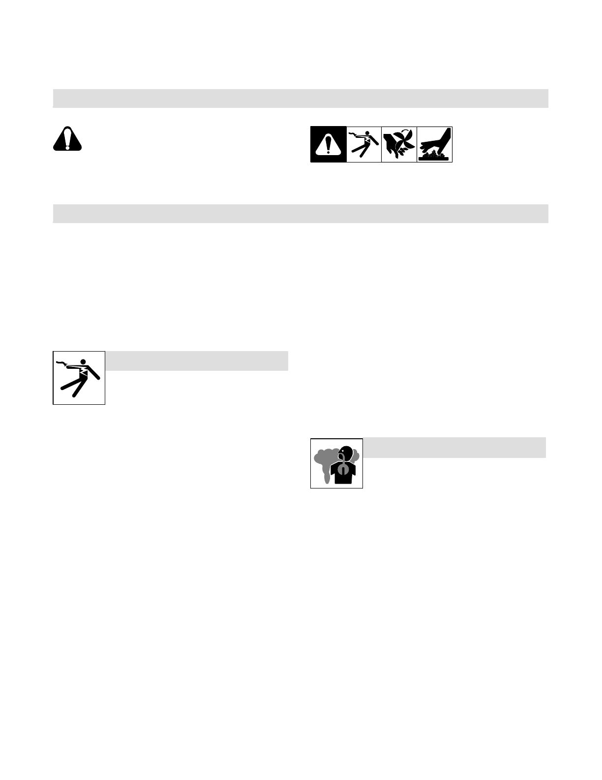
Y Avertissement : se protéger et protéger les autres contre le risque de blessure — lire et respecter ces consignes.
2-1. Symboles utilisés
safety_ihom 5/05
Symbole graphique d’avertissement ! Attention ! Cette procédure
comporte des risques possibles ! Les dangers éventuels sont
représentés par les symboles graphiques joints.
Y Indique un message de sécurité particulier
. Signifie NOTE ; n’est pas relatif à la sécurité.
Ce groupe de symboles signifie Avertissement ! Attention ! Risques
d’ÉLECTROCUTION, ORGANES MOBILES et PARTIES CHAUDES.
Consulter les symboles et les instructions afférentes ci-dessous
concernant les mesures à prendre pour supprimer les dangers.
2-2. Risques de chauffage par induction
Y Les symboles représentés ci-dessous sont utilisés dans ce
manuel pour attirer l’attention et identifier les dangers possibles.
En présence de l’un de ces symboles, prendre garde et suivre
les instructions afférentes pour éviter tout risque. Les instructions
en matière de sécurité indiquées ci-dessous ne constituent
qu’un sommaire des instructions de sécurité plus complètes
fournies dans les normes de sécurité énumérées dans la
Section 2-5. Lire et observer toutes les normes de sécurité.
Y Seul un personnel qualifié est autorisé à installer, faire
fonctionner, entretenir et réparer cet appareil.
Y Pendant le fonctionnement, maintenir à distance toutes les
personnes, notamment les enfants de l’appareil.
UNE DÉCHARGE ÉLECTRIQUE peut entraîner
la mort.
Le contact de composants électriques peut provoquer
des accidents mortels ou des brûlures graves. Le
circuit électrique et les barres collectrices ou les
connexions de sortie sont sous tension lorsque
l’appareil fonctionne. Le circuit d’alimentation et les circuits internes
de la machine sont également sous tension lorsque l’alimentation est
sur marche. Des équipements installés ou reliés à la borne de terre de
manière incorrecte sont dangereux.
D Ne pas toucher aux pièces électriques sous tension.
D Protéger toutes les barres collectrices et les raccords de
refroidissement pour éviter de les toucher par inadvertance.
D Porter des gants isolants et des vêtements de protection secs et
sans trous.
D S’isoler de la pièce à couper et du sol en utilisant des housses ou
des tapis assez grands afin d’éviter tout contact physique avec la
pièce à couper ou le sol.
D D’autres consignes de sécurité sont nécessaires dans les conditions
suivantes : risques électriques dans un environnement humide ou
si l’on porte des vêtements mouillés ; sur des structures métalliques
telles que sols, grilles ou échafaudages ; en position coincée
comme assise, à genoux ou couchée ; ou s’il y a un risque élevé de
contact inévitable ou accidentel avec la pièce à souder ou le sol.
Dans ces conditions, voir ANSI Z49.1 énuméré dans les normes de
sécurité. En outre, ne pas travailler seul !
D Couper l’alimentation d’entrée avant d’installer l’appareil ou
d’effectuer l’entretien. Verrouiller ou étiqueter la sortie d’alimentation
selon la norme OSHA 29 CFR 1910.147(se reporter aux Principales
normes de sécurité).
D N’utiliser que des tuyaux de refroidissement non conducteurs ayant
une longueur minimale de 457 mm pour garantir l’isolation.
D Installer le poste correctement et le mettre à la terre convenablement
selon les consignes du manuel de l’opérateur et les normes nationales,
provinciales et locales.
D Toujours vérifier la terre du cordon d’alimentation. Vérifier et s’assurer
que le fil de terre du cordon d’alimentation est bien raccordé à la
borne de terre du sectionneur ou que la fiche du cordon est
raccordée à une prise correctement mise à la terre.
D En effectuant les raccordements d’entrée, fixer d’abord le conducteur
de mise à la terre approprié et revérifier les connexions.
D Vérifier fréquemment le cordon d’alimentation afin de s’assurer qu’il
n’est pas altéré ou à nu, le remplacer immédiatement s’il l’est. Un fil à
nu peut entraîner la mort.
D L’équipement doit être hors tension lorsqu’il n’est pas utilisé.
D Ne pas utiliser des câbles usés, endommagés, de grosseur insuffisante
ou mal épissés.
D Ne pas enrouler les câbles autour du corps.
D Ne pas toucher le circuit électrique si l’on est en contact avec la pièce,
la terre ou le circuit électrique d’une autre machine.
D N’utiliser qu’un matériel en bon état. Réparer ou remplacer sur-le-
champ les pièces endommagées. Entretenir l’appareil conformément
à ce manuel.
D Porter un harnais de sécurité si l’on doit travailler au-dessus du sol.
D S’assurer que tous les panneaux et couvercles sont correctement
en place.
Il reste une TENSION DC NON NÉGLIGEABLE dans
les sources de soudage onduleur quand on a coupé
l’alimentation.
D Avant de toucher des organes internes, couper l’onduleur, débrancher
l’alimentation et décharger les condensateurs d’alimentation
conformément aux instructions indiquées dans la partie maintenance.
Le chauffage à induction de certains matériaux,
adhésifs et flux génère des fumées et des gaz. Leur
inhalation peut être dangereuse pour votre santé.
LES FUMÉES ET LES GAZ peuvent être dangereux.
D Ne pas mettre sa tête au-dessus des vapeurs. Ne pas respirer ces
vapeurs.
D À l’intérieur, ventiler la zone et/ou utiliser une ventilation forcée au
niveau de l’arc pour l’évacuation des fumées et des gaz.
D Si la ventilation est médiocre, porter un respirateur anti-vapeurs
approuvé.
D Lire et comprendre les spécifications de sécurité des matériaux
(MSDS) et les instructions du fabricant concernant les adhésifs, les
flux, les métaux, les consommables, les revêtements, les nettoyants
et les dégraisseurs.
D Travailler dans un espace fermé seulement s’il est bien ventilé ou en
portant un respirateur. Demander toujours à un surveillant dûment
formé de se tenir à proximité. Des fumées et des gaz provenant du
chauffage peuvent déplacer l’air, abaisser le niveau d’oxygène et
provoquer des lésions ou des accidents mortels. S’assurer que l’air
ambiant ne présente aucun danger.
D Ne pas chauffer dans des endroits se trouvant à proximité
d’opérations de dégraissage, de nettoyage ou de pulvérisation. La
chaleur peut réagir en présence de vapeurs et former des gaz
hautement toxiques et irritants.
D Ne pas surchauffer des métaux munis d’un revêtement tels que
l’acier galvanisé, plaqué au plomb ou au cadmium, à moins que le
revêtement ne soit enlevé de la zone chauffée, que la zone soit bien
ventilée et, si nécessaire, en portant un respirateur. Les revêtements et
tous les métaux contenant ces éléments peuvent dégager des fumées
toxiques s’ils sont surchauffés. Voir les informations concernant la
température dans les spécifications de revêtement MSDS.
OM-222 166 Page 5
Risque D’INCENDIE OU D’EXPLOSION.
D Ne pas surchauffer les composants ni les adhésifs.
D Attention aux risques d’incendie: tenir un extincteur
à proximité.
D Stocker des produits inflammables hors de la zone de travail.
D Ne pas placer l’appareil sur, au-dessus ou à proximité de surfaces
inflammables.
D Ne pas installer l’appareil à proximité de produits inflammables.
D Ne pas faire fonctionner l’appareil en atmosphère explosive.
LE CHAUFFAGE PAR INDUCTION peut provoquer
des brûlures.
D Des pièces ou de l’équipement chaud peuvent
provoquer des blessures.
D Ne pas toucher ou manipuler la tête/l’enroulement à induction
pendant le fonctionnement.
D Ne pas toucher des parties chaudes à mains nues.
D Laisser refroidir les composants ou équipements avant de les
manipuler.
D Tenir les bijoux et autres objets personnels en métal éloignés de la
tête/de l’enroulement pendant le fonctionnement.
2-3. Dangers supplémentaires en relation avec l’installation, le fonctionnement
et la maintenance
LA CHUTE DE L’APPAREIL peut blesser.
D Utiliser la poignée et demander à une personne
ayant la force physique nécessaire pour soulever
l’appareil.
D Déplacer lappareil à l’aide dun chariot ou d’un engin
similaire.
D Pour les appareils sans poignée utiliser un équipement d’une
capacité appropriée pour soulever l’appareil.
D En utilisant des fourches de levage pour déplacer l’unité, s’assurer
que les fourches sont suffisamment longues pour dépasser du côté
opposé de l’appareil.
LA PROJECTION DE PIÈCES DE METAL ou DE
COLLE peut provoquer des blessures aux yeux.
D Porter des lunettes de sécurité à coques latérales
ou un écran facial.
DES ORGANES MOBILES peuvent provoquer
des blessures.
D S’abstenir de toucher des organes mobiles tels
que des ventilateurs.
D Maintenir fermés et verrouillés les portes, panneaux,
recouvrements et dispositifs de protection.
LES CHAMPS MAGNÉTIQUES peuvent affecter
les stimulateurs cardiaques.
D Porteurs de stimulateur cardiaque, rester à distance.
D Les porteurs d’un stimulateur cardiaque doivent
d’abord consulter leur médecin avant de s’approcher
des opérations de chauffage à induction.
L’EMPLOI EXCESSIF peut SURCHAUFFER
L’ÉQUIPEMENT.
D Prévoir une période de refroidissement
D Réduire le courant de sortie ou le facteur de marche
avant de recommencer le chauffage.
D Respecter le cycle opératoire nominal.
LES CHARGES ÉLECTROSTATIQUES peuvent
endommager les circuits imprimés.
D Établir la connexion avec la barrette de terre
AVANT de manipuler des cartes ou des pièces.
D Utiliser des pochettes et des boîtes antistatiques
pour stocker, déplacer ou expédier des cartes PC.
LE RAYONNEMENT HAUTE FRÉQUENCE (HF)
risque de provoquer des interférences.
D Le rayonnement haute fréquence (HF) peut provo-
quer des interférences avec les équipements de
radio-navigation et de communication, les services
de sécurité et les ordinateurs.
D Demander seulement à des personnes qualifiées familiarisées
avec des équipements électroniques de faire fonctionner
l’installation.
D L’utilisateur est tenu de faire corriger rapidement par un électricien
qualifié les interférences résultant de l’installation.
D Si le FCC signale des interférences, arrêter immédiatement l’appareil.
D Effectuer régulièrement le contrôle et l’entretien de l’installation.
D Maintenir soigneusement fermés les portes et les panneaux des
sources de haute fréquence.
LIRE LES INSTRUCTIONS.
D Lire le manuel d’utilisation avant d’utiliser ou
d’intervenir sur l’appareil.
D Utiliser uniquement des pièces de rechange
Miller/Hobart.
2-4. Proposition californienne 65 Avertissements
Y Les équipements de soudage et de coupage produisent des
fumées et des gaz qui contiennent des produits chimiques
dont l’État de Californie reconnaît qu’ils provoquent des
malformations congénitales et, dans certains cas, des cancers.
(Code de santé et de sécurité de Californie, chapitre 25249.5 et
suivants).
Y Les batteries, les bornes et autres accessoires contiennent du
plomb et des composés à base de plomb, produits chimiques
dont l’État de Californie reconnaît qu’ils provoquent des
cancers et des malformations congénitales ou autres problèmes
de procréation. Se laver les mains après manipulation.
Pour les moteurs à essence :
Y Les gaz d’échappement des moteurs contiennent des produits
chimiques dont l’État de Californie reconnaît qu’ils provoquent
des cancers et des malformations congénitales ou autres
problèmes de procréation.
Pour les moteurs diesel :
Y Les gaz d’échappement des moteurs diesel et certains de leurs
composants sont reconnus par l’État de Californie comme
provoquant des cancers et des malformations congénitales ou
autres problèmes de procréation.
OM-222 166 Page 6
2-5. Principales normes de sécurité
Safety in Welding, Cutting, and Allied Processes, ANSI Standard Z49.1,
de Global Engineering Documents (téléphone : 1-877-413-5184, site In-
ternet : www.global.ihs.com).
Normes de sécurité et de santé, OSHA 29 CFR 1910, from Superintendent
of Documents, U.S. Government Printing Office, Washington, D.C.
20402.
Code électrique national, NFPA Standard 70, from National Fire Protection
Association, Batterymarch Park, Quincy, MA 02269.
Code électrique du Canada, partie 1, CSA Standard C22.1, from Canadian
Standards Association, Standards Sales, 178 Rexdale Boulevard,Rexdale,
Ontario, Canada M9W 1R3.
Practice For Occupational And Educational Eye And Face Protection,
ANSI Standard Z87.1, de American National Standards Institute, 11 West
42nd Street, New York, NY 10036-8002 (téléphone : 212-642-4900, site
Internet : www.ansi.org).
2-6. Information EMF
Considérations relatives au chauffage à induction et aux effets des champs
électriques et magnétiques basse fréquence.
Le texte suivant est extrait des conclusions générales Département du
Congrès U.S., Office of Technology Assessment, Effets biologiques des
champs magnétiques et électriques basse fréquence Background Paper,
OTA-BP-E-53 (Washington, DC: U.S. Government Printing Office, May
1989): “. . . on dispose maintenant d’importantes découvertes scientifiques
reposant sur des expériences effectuées dans le domaine cellulaire et
des études réalisées sur des animaux et des personnes qui démontrent
clairement que des champs magnétiques basse fréquence peuvent
avoir une interaction et produire des changements dans les systèmes
biologiques. Alors que la plus grande partie de cet ouvrage est d’une très
grande qualité, les résultats sont complexes. La compréhension scienti-
fique courante ne nous permet pas encore d’interpréter la preuve fournie
dans un seul ouvrage cohérent. Il est encore plus frustrant de ne pas
pouvoir tirer des conclusions définitives en ce qui concerne les problèmes
de risque possible ou de proposer des recommandations scientifiques
claires pour des stratégies à suivre en vue de minimiser ou de prévenir
des risques potentiels.”
Pour réduire les champs magnétiques sur le poste de travail, appliquer
les procédures suivantes :
4. Disposer le câble de sortie d’un côté à distance de l’opérateur
5. Ne pas enrouler ou draper le câble électrique autour du corps.
6. Placer la source de courant et le câble le plus loin possible de
l’opérateur.
En ce qui concerne les stimulateurs cardiaques
Les porteurs de stimulateur cardiaque doivent consulter leur médecin avant
de souder, d’approcher des opérations de soudage ou de chauffage
par induction. Si le médecin approuve, il est recommandé de suivre les
procédures précédentes.
OM-222 166 Page 7
SECTION 3 DEFINITIONS
3-1. Warning Label Definitions
Warning! Watch Out! There are
possible hazards as shown by the
symbols.
1 Electric shock from wiring can
kill.
1.1 Wear dry insulating gloves.
Do not wear wet or damaged
gloves.
1.2 Disconnect input plug or
power before working on
machine.
2 Induction heating can cause
injury or burns from hot items
such as rings, watches, or
parts.
2.1 Do not wear metal jewelry and
other metal personal items
such as rings and watches
during operation.
2.2 Do not touch hot parts or hot
head/coil.
3 Induction heating sparks can
cause fire. Do not overheat
parts and adhesives.
3.1 Keep flammables away from
heating operation. Do not heat
near flammables.
3.2 Heating sparks can cause
fires. Have a fire extinguisher
nearby and have a
watchperson ready to use it.
4 Breathing heating fumes can
be hazardous to your health.
Read Material Safety Data
Sheets (MSDSs) and
manufacturer’s instructions for
material used.
4.1 Keep your head out of the
fumes.
4.2 Use forced ventilation or local
exhaust to remove the fumes.
4.3 Use ventilating fan to remove
fumes.
5 Always wear safety glasses
or goggles during and around
heating operations to prevent
possible injury.
5.1 Wear either safety glasses or
full goggles depending on
type of operation and nearby
processes.
6 Do not remove or paint over
(cover) the label.
7 Become trained and read the
instructions before working on
the machine or heating.
190 025
OM-222 166 Page 8
3-1. Warning Label Definitions (Continued)
1 Warning! Watch Out! There
are possible hazards as
shown by the symbols.
2 Electric shock from wiring can
kill.
3 Overuse can cause
overheating. Follow rated duty
cycle.
4 Disconnect input plug or
power before working on
machine.
5 Become trained and read the
instructions before working on
the machine.
6 Connect green or
green/yellow grounding
conductor to ground terminal.
7 Connect input conductors (L1,
L2 And L3) to line terminals.
194 466
12
4
5
3
6
7
227 085-A
123 4
1 Warning! Watch Out! There
are possible hazards as
shown by the symbols.
2 Electric shock from wiring can
kill.
3 Disconnect input plug or
power before working on
machine.
4 Do not touch input
capacitor(s). Allow time for
capacitor(s) to discharge.
Check input capacitor(s)
voltage (see Section 9-7).
OM-222 166 Page 9
226 534-B
3-2. Rating Label For CE Products
For label location
see Section 4-2.
3-3. Symbols And Definitions
Some symbols are found only on CE products.
Note
A
Amperes
V
Volts Alternating Current
X
Duty Cycle
IP
Degree Of
Protection
Hz
Hertz Circuit Protection Output
Increase Line Connection
I
1
Primary Current
I
2
Rated Current
U
1
Primary Voltage
U
2
Load Voltage Read Instructions
Three Phase Static
Frequency Con-
verter-Transform-
er-Frequency Con-
verter
I
1max
Rated Maximum
Supply Current
P
1max
Maximum Power
Consumption
Three Phase Percent
Remote Panel/Local High Temperature Voltage Input
Off On
OM-222 166 Page 10
SECTION 4 INSTALLATION
4-1. Specifications
Output
Frequency
Rated Output
Required
Reflective
Inductance
Amperes Input at
Rated Load Output
50 or 60 Hz,
Three-Phase
Overall
Dimensions
Weight
Frequency
Single
Output
Dual
Output
I
n
d
uc
t
ance
400 V 460 V 575 V
kVA kW
Dimensions
5 To 30
kHz
35 kW At
100% Duty
Cycle
350 A
(RMS), 700
V (RMS)
35 kW At
100% Duty
Cycle
700 A
(RMS),
700 V
(RMS)
2.5 To 50
μh
60 A 50 A 40 A 39 37
Length: 36-3/4 in
(993 mm)
Width: 21-1/2 in
(546 mm)
Height: 29 in
(737 mm)
227 lb
(103 kg)
*While idling
WARNING
HIGH-FREQUENCY RADIATION can interfere with radio navigation, safety services,
computers, and communications equipment.
Have only qualified person familiar with electronic equipment perform this installation.
The user is responsible for having a qualified electrician promptly correct any interference problem resulting from the installation.
If notified by the FCC about interference, stop using the equipment at once.
Have the installation regularly checked and maintained.
Keep high-frequency source doors and panels tightly shut.
OM-222 166 Page 11
4-2. Selecting A Location
1 Lifting Eye
2 Lifting Forks
Use lifting eye or lifting forks to
move unit.
If using lifting forks, extend forks
beyond opposite side of unit.
3 Rating Label (Non CE Models
Only)
Use rating label to determine input
power needs. Label located under
front access door.
4 Plate Label (CE Models Only)
Label located under power switch.
5 Rating Label (CE Models
Only)
Use rating label to determine input
power needs.
6 Line Disconnect Device
Locate unit near correct input
power supply.
Y Special installation may be
required where gasoline or
volatile liquids are present
see NEC Article 511 or CEC
Section 20.
3
6
18 in
(460 mm)
18 in
(460 mm)
OR
1
2
Movement
Location And Airflow
4
5
803 992-B
OM-222 166 Page 12
4-3. Tipping
Y Be careful when placing or
moving unit over uneven
surfaces.
4-4. Electrical Service Guide
50 Hz
Three
Phase
60 Hz Three Phase
Input Voltage 400 460 575
Input Amperes At Rated Output 60 50 40
Max Recommended Standard Fuse Or Circuit Breaker Rating In Amperes
1
Circuit Breaker
1
, Time-Delay
2
70 61 45
Normal Operating
3
80 70 60
Min Input Conductor Size In AWG
4
6 8 8
Max Recommended Input Conductor Length In Feet (Meters)
254
(77)
214
(65)
334
(102)
Min Grounding Conductor Size In AWG
4
8 8 10
Reference: 2005 National Electrical Code (NEC) (including article 630)
1 Choose a circuit breaker with time-current curves comparable to a Time Delay Fuse.
2 Time-Delay fuses are UL class RK5 .
3 Normal Operating (general purpose - no intentional delay) fuses are UL class K5 (up to and including 60 amp), and UL class H ( 65 amp and above).
4 Conductor data in this section specifies conductor size (excluding flexible cord or cable) between the panelboard and the equipment per NEC Table
310.16. If a flexible cord or cable is used, minimum conductor size may increase. See NEC Table 400.5(A) for flexible cord and cable requirements.
Y Caution: Failure to follow these fuse and circuit breaker recommendations could create an electric shock or fire hazard. These
recommendations are for a dedicated branch circuit that applies to the rated output and duty cycle of the welding power source.
OM-222 166 Page 13
4-5. Connecting 3-Phase Input Power For 460/575 Volt Models
803 994-C
3/8 in
Tools Needed:
Y Installation must meet all National
and Local Codes have only quali-
fied persons make this installation.
Y Disconnect and lockout/tagout in-
put power before connecting input
conductors from unit.
Y Make input power connections to
the welding power source first.
Y Always connect green or green/
yellow conductor to supply
grounding terminal first, and never
to a line terminal.
. The circuitry in this unit automatically
adapts the power source to the
primary voltage being applied. Check
input voltage available at site. This
unit can be connected to either 460 or
575 VAC input power.
See rating label on unit and check input
voltage available at site.
1 Input Power Conductors (Customer
Supplied Cord)
Select size and length of conductors using
Section 4-4. Conductors must comply with
national, state, and local electrical codes.
If applicable, use lugs of proper amperage
capacity and correct hole size.
Welding Power Source Input Power
Connections
2 Strain Relief
Route conductors (cord) through strain re-
lief and tighten screws.
3 Machine Grounding Terminal
4 Green Or Green/Yellow Grounding
Conductor
Connect green or green/yellow grounding
conductor to welding power source
grounding terminal first.
5 Welding Power Source Line
Terminals
6 Input Conductors L1 (U), L2 (V) And
L3 (W)
Connect input conductors L1 (U), L2 (V)
and L3 (W) to welding power source line
terminals.
Close and secure access door on welding
power source.
Disconnect Device Input Power
Connections
7 Disconnect Device (switch shown in
OFF position)
8 Disconnect Device (Supply)
Grounding Terminal
Connect green or green/yellow grounding
conductor to disconnect device grounding
terminal first.
9 Disconnect Device Line Terminals
Connect input conductors L1 (U), L2 (V)
And L3 (W) to disconnect device line
terminals.
10 Over-Current Protection
Select type and size of over-current
protection using Section 4-4 (fused dis-
connect switch shown).
Close and secure door on line disconnect
device. Remove lockout/tagout device,
and place switch in the On position.
GND/PE Earth Ground
7
2
10
8
4
9
1
6
3
4
3
6
5
OM-222 166 Page 14
Ref. 804 430-A
Tools Needed:
4-6. Connecting 3-Phase Input Power For 400/460 Volt Models
3/8 in
Y Installation must meet all National and
Local Codes have only qualified per-
sons make this installation.
Y Disconnect and lockout/tagout input
power before connecting input con-
ductors from unit.
Y Make input power connections to the
welding power source first.
Y Always connect green or green/yellow
conductor to supply grounding termi-
nal first, and never to a line terminal.
. The circuitry in this unit automatically
adapts the power source to the primary
voltage being applied. Check input
voltage available at site. This unit can be
connected to either 400 or 460 VAC input
power.
See rating label on unit and check input volt-
age available at site.
1 Input Power Conductors (Customer
Supplied Cord)
Select size and length of conductors using
Section 4-4. Conductors must comply with
national, state, and local electrical codes. If
applicable, use lugs of proper amperage
capacity and correct hole size.
Welding Power Source Input Power Con-
nections
2 Strain Relief
Route conductors (cord) through strain relief
and tighten screws.
3 Machine Grounding Terminal
4 Green Or Green/Yellow Grounding
Conductor
Connect green or green/yellow grounding
conductor to welding power source grounding
terminal first.
5 Welding Power Source Line Terminals
6 Input Conductors L1 (U), L2 (V) And L3
(W)
Connect input conductors L1 (U), L2 (V) and
L3 (W) to welding power source line terminals.
Close and secure access door on welding
power source.
Disconnect Device Input Power Connec-
tions
7 Disconnect Device (switch shown in
OFF position)
8 Disconnect Device (Supply) Grounding
Terminal
Connect green or green/yellow grounding
conductor to disconnect device grounding ter-
minal first.
9 Disconnect Device Line Terminals
Connect input conductors L1 (U), L2 (V) And
L3 (W) to disconnect device line terminals.
10 Over-Current Protection
Select type and size of over-current protection
using Section 4-4 (fused disconnect switch
shown).
Close and secure door on line disconnect de-
vice. Remove lockout/tagout device, and
place switch in the On position.
7
8
1
5
4
2
3
4
L1
L2
L3
6
9
10
= GND/PE Earth Ground
3
6
1 / 1

Ask a question and I''ll find the answer in the document

Finding information in a document is now easier with AI

Ask the document

in other languages