Page is loading ...

DIAGNOSTIC GUIDE
Before servicing, check the following:
■
Make sure there is power at the wall outlet.
■
Has a household fuse blown or circuit breaker
tripped?Was a regular fuse used? Use a time-
delay fuse.
■
Is dryer vent properly installed and clear of lint
or other obstructions?
■
All tests/checks should be made with
a VOM (volt-ohm-milliammeter) or DVM
(digital-voltmeter) having a sensitivity
of 20,000 Ω per volt DC or greater.
■
Check all connections before replacing
components. Look for broken or loose wires,
failed terminals,or wires not pressed into
connectors far enough.
■
A potential cause of a controlnot functioning is
corrosion on connections.Observe connections
and check for continuity with an ohmmeter.
■
Connectors: Look at top of connector. Check
for broken or loose wires. Check for wires not
pressed into connector far enough to engage
metal barbs.
■
Resistance checks must be made with dryer
unplugged or power disconnected.
SERVICE DIAGNOSTIC MODE ENTRY
These tests allow factory or service personnel
to test and verify all inputs to the machine control
electronics.You may want to do a quick and
overall checkup of the dryer with these tests
before going to specific troubleshooting tests.
FOR SERVICE TECHNICIAN ONLY - DO NOT REMOVE OR DESTROY
PART NO. W10386307B PAGE 1
IMPORTANT
Electrostatic Discharge (ESD)
Sensitive Electronics
ESD problems are present everywhere. ESD may damage or weaken the
machine control electronics.The new control assembly may appear to work well
after repair is finished, but failure may occur at a later date due to ESD stress.
■
Use an anti-static wrist strap. Connect wrist strap to green ground
connection point or unpainted metal in the appliance.
-OR-
■
Touch your finger repeatedly to a green ground connection point or
unpainted metal in the appliance.
■
Before removing the part from its package, touch the anti-static bag
to a green ground connection point or unpainted metal in the appliance.
■
Avoid touching electronic parts or terminal contacts; handle electronic
control assembly by edges only.
■
When repackaging failed machine control electronics in anti-static bag,
observe above instructions.

ACTIVATING THE SERVICE
DIAGNOSTIC MODE
FOR SERVICE TECHNICIAN ONLY - DO NOT REMOVE OR DESTROY
PAGE 2
1. Be sure the dryer is in standby mode
(plugged in with all indicators off,or with only the
DONE [on some models] or COMPLETE [on some
models] indicator on).
2. Select any three buttons and follow the steps
below, using the same buttons (remember the
buttons and the order that the buttons were
pressed):
Within 8 seconds,
Press and Release the 1st selected button,
Press and Release the 2nd selected button,
Press and Release the 3rd selected button;
Repeat this 3 button sequence 2 more times.
3. If this test mode has been entered
successfully, all indicators on the console are
illuminated for 5 seconds, with some models
showing
88 in the Estimated Time Remaining
two-digit display. If there are no saved fault
codes,all indicators on the console will
momentarily turn off, then only the seven
segment display (on some models) will come
back on and display
88, and, on other models,
only the WET indicator will come on and stay
on constantly.
SERVICE DIAGNOSTIC MENU TABLE
Button Press Function Behavior
1st Button Momentary press Activates User Interface/
Control System Test
Press and hold Exits Service Diagnostics
for 5 secs.
2nd Button Momentary press Triple Beep
Press and hold Triple Beep
for 5 secs.
3rd Button Momentary press Displays Next Error Code
Press and hold Clears the Error Codes
for 5 secs.
If any button fails to change the function,
something is faulty with the button, and it will
not be possible to enter the diagnostic mode
using that button. Replace the user interface
and housing assembly. See Accessing &
Removing the Electronic Assemblies, page 21.
If no indicators come on after selecting the
cycle, go to TEST #1, page 12.
Indication 2:
Console indicators begin
flashing immediately.
Action:
If console indicators begin flashing on
and off immediately, replace the user interface.
See Accessing & Removing the Electronic
Assemblies, page 21.
Activation With Saved Fault Codes
(models with seven segment display)
If there is a saved fault code, it will be flashing
in the display. Review the Fault/Error Codes table,
page 4, for the recommended procedure.
If there is no saved fault code,
88 will be displayed.
(models without seven segment display)
If there is a saved fault code, only the WET
indicator will be flashing. Review the Fault/Error
Codes table for the recommended procedure.
Fault/Error Code Display Method
(models with seven segment display)
Fault codes are displayed by alternately showing
F# and E#. All fault codes have an F# and an E#.
The F# indicates the suspect System/Category.
The E# indicates the suspect Component system.
(models without seven segment display)
Fault codes are displayed by a series of flashes of
the WET indicator.All fault codes have an F# and
an E#.The first set of 0.5 second flashes should
be counted and used as the F#.The F# indicates
the suspect System/Category.The second set of
0.5 second flashes should again be counted and
used as the E#. The E# indicates the suspect
Component system.The transition from the F# to
the E# is indicated by a 2 second pause.After the
E# is displayed, there will be a 5 second pause
before the F# is flashed again.
Below shows how F3E6 would be displayed:
3 flashes ➔ 2 second pause ➔ 6 flashes ➔ 5 second pause
Unsuccessful Activation
If entry into diagnostic mode is unsuccessful,
refer to the following indications and actions:
Indication 1:
None of the indicators or display
turns on.
Action:
Select any cycle.
If indicators come on, try to change the
function for the three buttons used to activate
the diagnostic test mode.

Advancing Through Saved Fault/
Error Codes
Procedure for advancing through saved fault codes:
Press and release Most
the 3rd button beep recent fault
used to activate
tone
code is
Service Diagnostics displayed.
Second most
Repeat
beep recent fault
tone
code is
displayed.
Third most
Repeat
beep recent fault
tone
code is
displayed.
Fourth most
Repeat
beep recent fault
tone
code is
displayed.
Repeat
Triple beep, then back to
the most recentfault code.
Up to four Fault/Error codes may be stored.
When the oldest fault code is displayed,additional
presses of the 3rd button will result in a triple
beep, then display of (or cycling back to) the most
recent fault code.If each press of the 3rd button
results in a triple beep and the display shows
88
(on models with seven segment display) or the
WET indicator is constantly lit (on models without
seven segment display), no saved fault codes
are present.
FOR SERVICE TECHNICIAN ONLY - DO NOT REMOVE OR DESTROY
PAGE 3
Clearing Fault Codes
To clear fault codes,enter Service Diagnostic mode.
Then press and hold the 3rd button used to enter
Service Diagnostic mode for 5 seconds. Once the
fault codes are successfully erased,the seven
segment display will show
88 (on models with
seven segment display) or the WET indicator will
be lit constantly (on models without seven
segment display).

FOR SERVICE TECHNICIAN ONLY - DO NOT REMOVE OR DESTROY
PAGE 4
FAULT/ERROR CODES
The fault codes below would be indicated when attempting to start a drying cycle, or after activating the
service diagnostic mode.
Code Description Explanation/Recommended Procedure
pf Power Failure PF indicates that a power failure occurred while the
(on some models) dryer was running.
■ Press START/PAUSE to continue the cycle, or press
POWER or POWER/CANCEL (Maytag models) to clear
the display.
f1e1 Primary Control Failure F1E1 indicates a primary control failure.
■ Replace the machine control electronics. See
Accessing & Removing the Electronic Assemblies,
page 21.
f2 e 1 Keypad/User F2E1 indicates a stuck button or user interface
Interface Failure mismatch.This fault code will ONLY appear when
in the service diagnostic mode.
■ See TEST #5, page 20.
f3 e 1 Exhaust Thermistor Open F3E1 indicates that the thermistor is open.
■ See TEST #3a,page 17.
f3 e2 Exhaust Thermistor Shorted F3E2 indicates that the thermistor has shorted.
■ See TEST #3a,page 17.
f3 e6 Moisture Sensor Open F3E6 indicates that the moisture sensor strip is open.
This fault code will ONLY appear when in the service
diagnostic mode.
■ See TEST #4, page 18.
f3 e 7 Moisture Sensor Shorted F3E7 indicates that the moisture sensor strip has
shorted.This fault code will ONLY appear when in the
service diagnostic mode.
■ See TEST #4, page 18.
f8 e 1 Water Valve Failure F8E1 indicates that no voltage is detected at the water
(Steam Models Only) valve relay.This fault code will ONLY appear when in
the service diagnostic mode.
■ See TEST #7, page 21.
Status AUTO CYCLE
Indicator Delicate Casual Normal Eco Normal Heavy Duty
“ON” “ON” “OFF” “OFF” “OFF”
“ON” “ON” “OFF” “OFF” “OFF”
“ON” “ON” “OFF” “OFF” “ON”
“OFF” “ON” “OFF” “ON” “OFF”
FOR SERVICE TECHNICIAN ONLY - DO NOT REMOVE OR DESTROY
PAGE 5
USER INTERFACE/
CONTROL SYSTEM TEST
Entry Procedure:
Press and release the first button used to activate
Service Diagnostic mode.The following tests will
be available.
NOTE: The Service Diagnostic mode must be
activated before activating the User Interface/
Control System test; see procedure on page 2.
Active Fault Code Display in User
Interface/Control System Test:
If the display (on models with seven segment
display) or WET indicator (on models without
seven segment display) begins flashing while in
User Interface/Control System test,it is displaying
an active fault code. Active fault codes are codes
that are currently failing. Only one active fault
code can be displayed at a time.
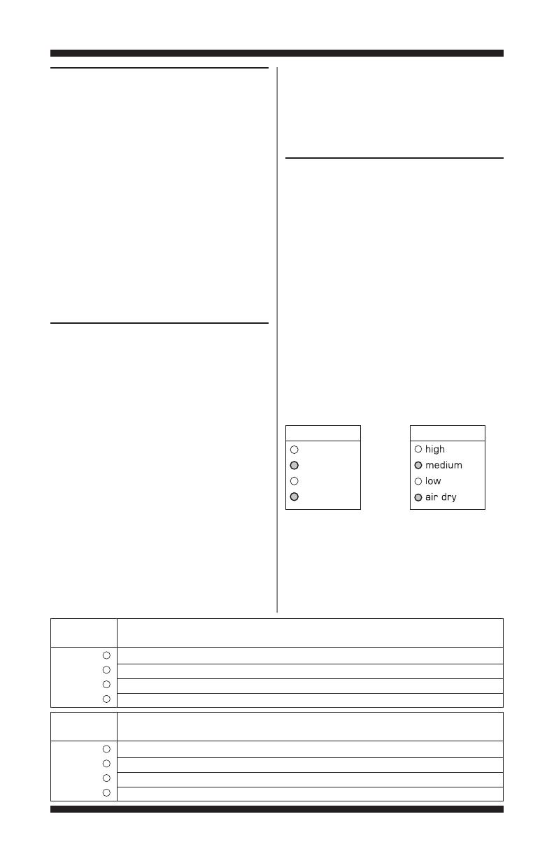
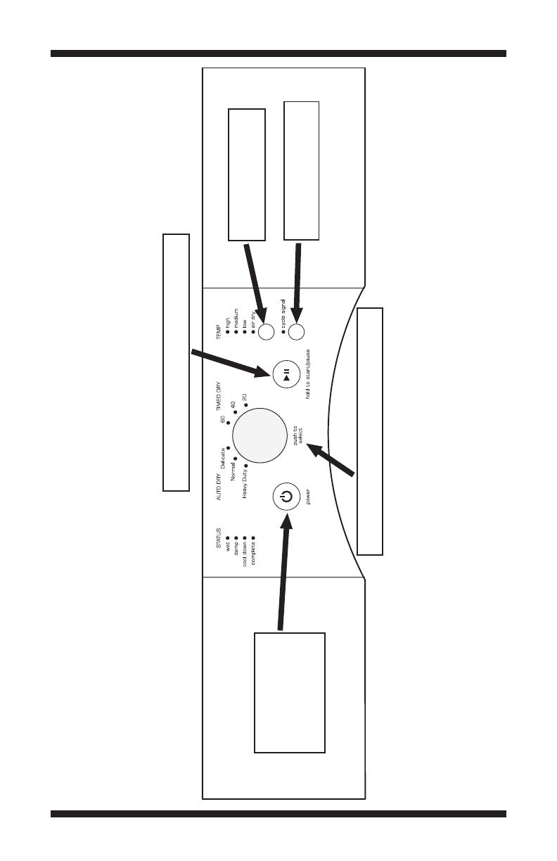
Diagnostic Test: Console Buttons
and Indicators
(models with seven segment display
and some models without seven
segment display)
Pressing buttons and rotating the cycle selector
will turn off the corresponding indicator and
sound a beep as shown in figure 1,Console
Diagnostics. If indicators fail to come on and beep
after pressing buttons and rotating the cycle
selector, go to TEST #5, page 20.
(model 9150 without seven
segment display)
Pressing buttons will turn off the corresponding
indicator and sound a beep as shown in figure 1,
Console Diagnostics. Rotating the cycle selector
will cause the status indicators to display the
index of the cycle selector. See table below for
details.If indicators fail to come on and beep after
pressing buttons and rotating the cycle selector,
go toTEST #5, page 20.
(all models)
NOTE: A second press of the POWER (POWER/
CANCEL on Maytag models) button while in
Console Buttons and Indicators mode exits the
Service Diagnostic mode and returns the dryer
to standby mode.
Diagnostic Test: Door Switch
(models with seven segment display)
Opening the door should cause a beep and an
alphanumeric number to be displayed. Closing
the door should cause a beep and
88 to be
displayed.
If opening the door fails to cause a beep and
an alphanumeric number to be displayed,go
toTEST #6, page 20.
(models without seven segment display)
When the door is opened, for electric dryers, the
dryer will beep once and theWET status indicator
will turn on. For gas dryers, the dryer will beep
twice and the DONE or COMPLETE (depending on
model) status indicator will turn on.With the door
open, theTEMP indicators will be used to display
the Control Software ID.TheTEMP indicators will
be“On”or“Off” according to the table below.
If opening the door fails to cause a beep(s),
Control Software ID,or fuel type to be indicated,
go toTEST #6, page 20.
Wet
Damp
Cool Down
Done
Status TIMED CYCLE
Indicator 60 min 40 min Small Load
“ON” “ON” “OFF”
“OFF” “OFF” “ON”
“OFF” “OFF” “ON”
“ON” “OFF” “ON”
Wet
Damp
Cool Down
Done
Temp Indicators
High
Medium
Low
Air Dry
Temp Indicators
or
Diagnostic Test: Moisture Sensor
Open the door and locate two metal strips on the
face of the lint screen housing. Bridge these strips
with a wet cloth or a finger. If a beep is heard and
an alphanumeric number is displayed on the
console (on models with seven segment display)
or STATUS and/or TEMP indicators change (on
models without seven segment display), the
sensor is OK. If not, or if a beep tone is heard
before bridging the moisture strips, go toTEST
#4, page 18.
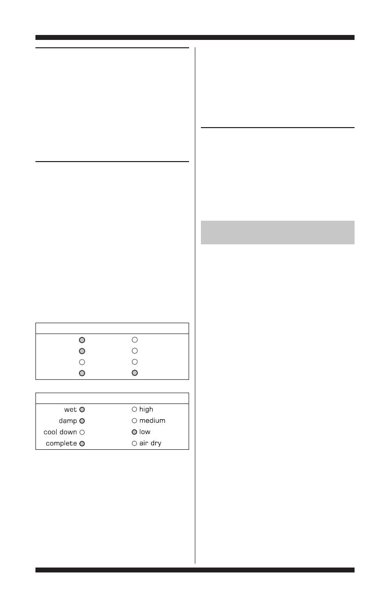
Diagnostic Test: Console ID, Motor, Heater,
and Water Valve (on steam models)
(models with seven segment display)
Close the door. Press the START button.The dryer
will beep and the motor, heater, and water valve
(on steam models) will turn on, and the display
will show the following Console ID: 8a, 80, or 83,
depending on model.
(models without seven segment display)
Close the door. Press the START button.The dryer
will beep and the motor and heater will turn on.
The STATUS and TEMP indicators will display the
console ID, and the indicators should be lit up as
indicated in the table below.
(all models)
While motor is running, pressing the START
button a second time will turn off the motor,
heater, and water valve (on steam models).Each
additional press of the START button will toggle
the motor, heater, and water valve (on steam
models) on and off.
If the Console ID is not displayed, replace
the user interface and housing assembly. See
Accessing & Removing the Electronic Assemblies,
page 21.
Press and hold the 1st button used to enter the
Service Diagnostic mode for 5 seconds to exit
diagnostics.
DEACTIVATING THE SERVICE
DIAGNOSTIC MODE
FOR SERVICE TECHNICIAN ONLY - DO NOT REMOVE OR DESTROY
PAGE 6
Status Indicators Temp Indicators
Wet
Damp
Cool Down
Done
High
Medium
Low
Air Dry
Status Indicators Temp Indicators
or
If the motor does not turn on, go toTEST #2,
page 14.
If no heat is detected, go to TEST #3,page 15.
On steam models only, if no water is detected,
go toTEST #7, page 21.
NOTE: On steam models only, press the POWER
button.
DEACTIVATING TEST MODES
Deactivating the User Interface/
Control System Test
This mode can be exited by either of the two
methods listed below:
1. Pressing the POWER button twice.
2. Pressing and holding the 1st button used to
activate the Service Diagnostic mode for 5 seconds.
Console ID Indicator Status Table
FOR SERVICE TECHNICIAN ONLY - DO NOT REMOVE OR DESTROY
PAGE 7
Sensing
Wet
Damp
Cool
Down
Done
Wrinkle
Shield
Steam
Control Lock
First press turns
off the Status, Control
Lock, and Steam
indicators. Second
press exits Service
Diagnostic mode
and dryer returns
to standby mode.
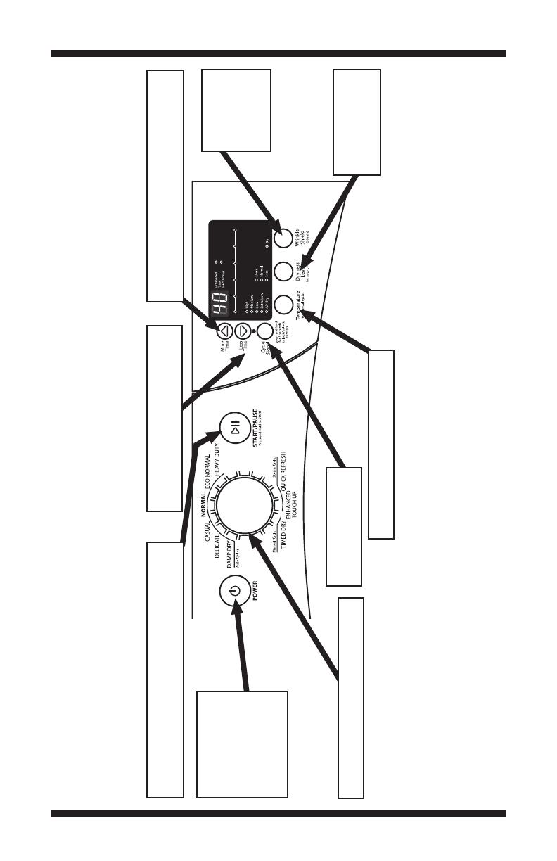
Each press toggles the motor, heater, and water valve
state. The display will show the UI ID code. On Off
or Off On.
➔
➔
Each press toggles state of the least
significant digit (Right) of the seven
segment display. On Off or Off On.
➔➔
Each press toggles state of the most significant
digit (Left) of the seven segment display. On Off
or Off On.
➔
➔
Each press
toggles state
of Wrinkle
Shield indicator.
On Off or
Off On.
➔
➔
Each press toggles
state of Dryness Level
indicators. On Off
or Off On.
➔
➔
Each press toggles state of Temperature
indicators. On Off or Off On.
➔➔
Each press toggles state
of Cycle Signal indicator.
On Off or Off On.
➔➔
Rotating the encoder will turn indicators on
and off individually. On
➔ Off or Off ➔ On.
WHIRLPOOL CONTROL PANEL WITH SEVEN SEGMENT DISPLAY (steam model 9371 shown – features and appearance may vary)
Figure 1a. Console Diagnostics.
FOR SERVICE TECHNICIAN ONLY - DO NOT REMOVE OR DESTROY
PAGE 8
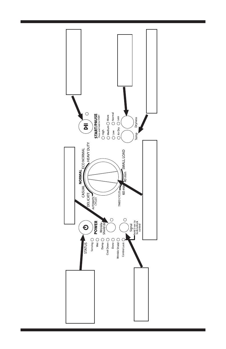
First press turns off
the Control Lock and
Wrinkle Shield indicators.
Second press exits Service
Diagnostic mode and dryer
returns to standby mode.
Each press toggles the Start/Pause
indicator and motor and heater
state. On Off or Off On.
➔➔
Toggles state of Temp indicators with each
press. On Off or Off On.
➔➔
Toggles state of Signal
indicator with each press.
On Off or Off On.
➔➔
Toggles state of Wrinkle Shield indicator
with each press. On Off or Off On.
➔➔
Toggles state of Dryness
indicators with each press.
On Off or Off On.
➔➔
When rotated, the Sensing indicator will turn off and
the remaining Status indicators will display the index
for each position.
WHIRLPOOL CONTROL PANEL WITHOUT SEVEN SEGMENT DISPLAY (model 9150 shown – features and appearance may vary)
Figure 1b. Console Diagnostics.
FOR SERVICE TECHNICIAN ONLY - DO NOT REMOVE OR DESTROY
PAGE 9
First press turns off
the Status indicators.
Second press exits
Service Diagnostic
mode and dryer returns
to standby mode.
Each press toggles the Start/Pause indicator and motor
and heater state. On Off or Off On.
➔➔
Toggles state of Temp
indicators with each press.
On Off or Off On.
➔➔
Toggles state of Cycle Signal
indicator with each press.
On Off or Off On.
➔➔
Starting with first press, indicators will turn off or on
one at a time with each press. On
➔ Off or Off ➔ On.
WHIRLPOOL/AMANA/INGLIS/MAGIC CHEF CONTROL PANEL WITHOUT SEVEN SEGMENT DISPLAY
(Whirlpool model 9050 shown – features and appearance may vary)
Figure 1c. Console Diagnostics.

FOR SERVICE TECHNICIAN ONLY - DO NOT REMOVE OR DESTROY
PAGE 10
First press turns off the Status, Control
Lock, and Steam indicators. Second
press exits Service Diagnostic mode and
dryer returns to standby mode.
Rotating the encoder will turn
indicators on and off individually.
On
➔ Off or Off ➔ On.
Each press toggles the motor and heater state. The
display will show the UI ID code. On Off or Off On.
➔➔
Each press toggles state of the least
significant digit (Right) of the seven
segment display. On Off or Off On.
➔➔
Each press toggles state of the most significant
digit (Left) of the seven segment display. On Off
or Off On.
➔
➔
Each press toggles state
of Cycle Signal indicator.
On Off or Off On.
➔➔
Each press toggles state
of Wrinkle Prevent indicator.
On Off or Off On.
➔➔
Each press toggles state of Dryness Level
indicators. On Off or Off On.
➔➔
Each press toggles state of Temp Level
indicators. On Off or Off On.
➔➔
MAYTAG CONTROL PANEL (steam model 301 shown – features and appearance may vary)
Figure 1d. Console Diagnostics.
FOR SERVICE TECHNICIAN ONLY - DO NOT REMOVE OR DESTROY
PAGE 11
TROUBLESHOOTING GUIDE Some tests will require accessing components.
Problem Possible Cause/Test
NOTE: Possible Cause/Tests MUST be performed
in the sequence shown for each problem.
Won’t power up. (No response 1. Supply connections. See TEST #1, page 12.
when buttons are pressed.)
2. Unplug dryer or disconnect power. Check
harness connections.
3. User interface and housing assembly.
See TEST #5, page 20.
Won’t start cycle when Start 1. If number display flashes, check to be sure the
button is pressed. door is completely shut, and press and hold down
START for about 1 second.
2. See TEST #2, page 14.
3. See TEST #6, page 20.
Won’t shut off when expected. 1. Check START/PAUSE button.
2. User interface and housing assembly.
See TEST #5, page 20.
3. Moisture sensor. See TEST #4, page 18.
Control won’t accept selections. User interface and housing assembly.
See TEST #5, page 20.
Won’t heat. 1. Check installation.
2. Unplug dryer or disconnect power. Check
harness connections.
3. Heater. See TEST #3, page 15.
Heats in air cycle. Heater. See TEST #3, page 15.
Shuts off before clothes are dry. 1. Check the dryness or dryness level
(depending on model) setting for auto cycles.
2. Check for full lint screen.
3. Check for clogged vent.
4. Moisture sensor. See TEST #4, page 18.
5. Dryness or dryness level (depending on model)
adjust. See TEST #4a, page 19.
Steam Models Only:
Water not dispensing. 1. Make sure a “Steam” cycle is selected.
2. See TEST #7, page 21.
FOR SERVICE TECHNICIAN ONLY - DO NOT REMOVE OR DESTROY
PAGE 12
TROUBLESHOOTING TESTS
NOTE: These checks are done with the dryer
unplugged or disconnected from power.
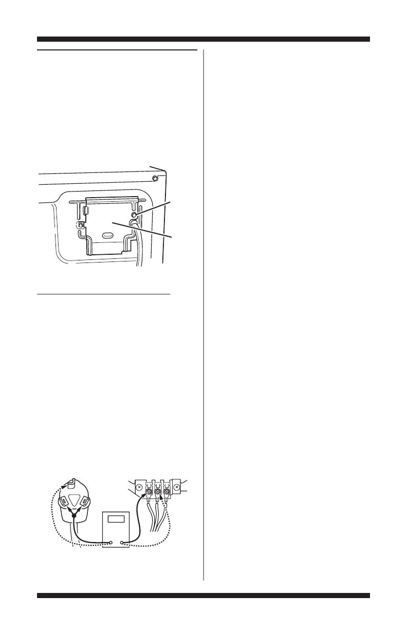
TEST #1 Supply Connections
This test assumes that proper voltage is present
at the outlet, and for U.S. installations, a visual
inspection indicates that the power cord is
securely fastened to the terminal block (electric
dryer) or wire harness connection (gas dryer).
ELECTRIC DRYER (U.S. Installations):
1. Unplug dryer or disconnect power.
2. Remove the cover plate from the top right
corner of the back of the dryer. See figure 2.
3. With an ohmmeter, check for continuity
between the neutral (N) terminal of the plug and
the center contact on the terminal block.See
figure 3a.
If there is no continuity, replace the power
cord and test the dryer.
If there is continuity, go to step 4.
4. In a similar way, check which terminal of the
plug is connected to the left-most contact on the
terminal block and make a note of it.This will be
L1 (black wire) in the wiringdiagram.See figure 3a.
If neither of the plug terminals have continuity
with the left-most contact of the terminal block,
replace the power cord and test the dryer.
5. Access the machine control electronics
without disconnecting any wiring to the control
board.See Accessing & Removing the Electronic
Assemblies, page 21.
6. With an ohmmeter, check for continuity
between the L1 terminal of the plug (found in step
4) and P9-2 (black wire) on the machine control
board.See figure 15,page 23.
If there is continuity, go to step 7.
If there is no continuity, check that wires to the
terminal block are mechanically secure. If so,
replace the main wire harness and test the dryer.
7. Check for continuity between the neutral (N)
terminal of the plug and P8-3 (white wire) on the
machine control board.
If there is continuity, go to step 8.
If there is no continuity and the mechanical
connections of the wire are secure, replace the
main wire harness.
8. Visually check that the P5 connector is
inserted all the way into the machine control
electronics.
9. Visually check that the user interface and
housing assembly is properly inserted into the
front console.
10. If both visual checks pass, replace the
user interface and housing assembly.
11. Reassemble all parts and panels.
12. Plug in dryer or reconnect power.
13. Activate the Service Diagnostic mode per
procedure on page 2. Then activate the User
Interface/Control System test and verify the repair
by completing the Buttons and Indicators test per
procedures on page 5.
14. If indicators still do not light, the machine
control electronics has failed:
Unplug dryer or disconnect power.
Replace the machine control electronics.
Reassemble all parts and panels.
Plug in dryer or reconnect power.
Activate the Service Diagnostic mode per
procedure on page 2. Then activate the User
Interface/Control System test and verify the repair
by completing the Buttons and Indicators test per
procedures on page 5.
Remove
Screw
Cover
Plate
CO M
N
L1
Power Cord
Plug
Terminal Block
Figure 2. Remove the cover plate.
Figure 3a. Plug-to-terminal connections
for electric dryer.
FOR SERVICE TECHNICIAN ONLY - DO NOT REMOVE OR DESTROY
PAGE 13
ELECTRIC DRYER (Canadian Installations):
1. Unplug dryer or disconnect power.
2. Remove the cover plate from the top right
corner of the back ofthedryer.See figure 2,page 12.
3. Access the machine control electronics
without disconnecting any wiring to the control
board.See Accessing & Removing the Electronic
Assemblies, page 21.
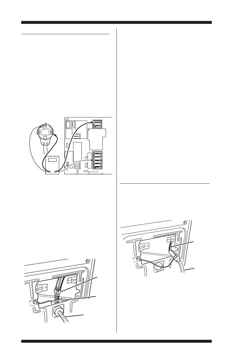
4. With an ohmmeter, check thecontinuity from
L1 and N plug terminalsof the powercord to the
terminals for L1 and N on the machine control
electronics. See figure 3b.
If continuity exists for both connections,
go to step 6.
If an open circuit is found,check the integrity of
the connections of the power cord to the harness
in the dryer; harness to the machine control board;
and, the integrity of the power cord itself.
5. If it is necessary to replace the power cord,
remove the retaining clip that secures the cord
to the back panel. See figure 4. Disconnect the
cord from the main harness and the ground wire
from the rear panel, then pull out the power cord.
6. Visually check that the P5 connector is inserted
all the way into the machine control electronics.
7. Visually check that the user interface and housing
assembly is properly inserted into the front console.
8. If both visual checks pass, replace the user
interface and housing assembly.
9. Reassemble all parts and panels.
10. Plug in dryer or reconnect power.
11. Activate the Service Diagnostic mode per
procedure on page 2. Then activate the User
Interface/Control System test and verify the repair
by completing the Buttons and Indicators test per
procedures on page 5.
12. If indicators still do not light, the machine
control electronics has failed:
Unplug dryer or disconnect power.
Replace the machine control electronics.
Reassemble all parts and panels.
Plug in dryer or reconnect power.
Activate the Service Diagnostic mode per
procedure on page 2. Then activate the User
Interface/Control System test and verify the repair
by completing the Buttons and Indicators test per
procedures on page 5.
GAS DRYER (U.S. and Canadian Installations):
1. Unplug dryer or disconnect power.
2. Remove the cover plate fromthe top right corner
of the back of the dryer. See figure 2, page 12.
3. Check that the power cord is firmly connected
to the dryer’s wire harness. See figure 5.
4. Access the machine control electronics
without disconnecting any wiring to the control
board.See figure 14a or 14b, page 22.
5. With an ohmmeter, check for continuity
between the neutral (N) terminal of the plug and
P8-3 (white wire) on the machine control board.
P9
1
5
1
P/N XXXXXX Rev X
Date Code YDDD-xx
XXXX-XXX
MADE IN COO
L1
CO M
P8
L1
N
Neu
N
Neu
Power Cord
Plug
Machine Control
Electronics
Figure 3b. Plug-to-terminal connections
for electric dryer.
Wire
Harness
Power
Cord
Figure 5. Power cord-to-wire harness
connection for gas dryer.
Wire
Harness
Power Cord
Retaining
Clip
Figure 4. Remove the retaining clip.
FOR SERVICE TECHNICIAN ONLY - DO NOT REMOVE OR DESTROY
PAGE 14
The left-hand side of figure 6 shows the position
of the neutral terminal (N) on the power cord plug.
Also see figure 15, page 23.
If there is continuity, go to step 6.
If there is no continuity, disconnect the white
wire of the harness from the power cord at the
location illustrated in figure 5,page 13.Test the
continuity of the power cord neutral wire as
illustrated in figure 6. If an open circuit is found,
replace the power cord. Otherwise, go to step 6.
6. In a similar way, check the continuity between
the L1 terminal of the plug and P9-2 (black wire)
on the control board.
If there is continuity, go to step 8.
If there is no continuity, check the continuity of
the power cord in a similar way to that illustrated
in figure 6, but for power cord’s L1 wire.
If an open circuit is found, replace the power
cord. Otherwise, go to step 7.
7. Replace the main harness.
8. Visually check that the P5 connector is inserted
all the way into the machine control electronics.
9. Visually check that the user interface and
housing assembly is properly inserted into the
front console.
10. If both visual checks pass, replace the
user interface and housing assembly.
11. Reassemble all parts and panels.
12. Plug in dryer or reconnect power.
13. Activate the Service Diagnostic mode per
procedure on page 2. Then activate the User
Interface/Control System test and verify the repair
by completing the Buttons and Indicators test per
procedures on page 5.
14. If indicators still do not light, the machine
control electronics has failed:
Unplug dryer or disconnect power.
Replace the machine control electronics.
Reassemble all parts and panels.
Plug in dryer or reconnect power.
Activate the Service Diagnostic mode per
procedure on page 2. Then activate the User
Interface/Control System test and verify the repair
by completing the Buttons and Indicators test per
procedures on page 5.
TEST #2 Motor Circuit
This test will check the wiring to the motor and
the motor itself.The following items are part of
this motor system:
Electric Gas
Part of Motor System Dryer Dryer
Harness/connection ✔✔
Thermal fuse ✔ no
Belt/belt switch ✔✔
Drive motor ✔✔
Centrifugal switch ✔✔
Door switch ✔✔
Machine control ✔✔
electronics.See ESD
information, page 1.
1. Unplug dryer or disconnect power.
2. Access the machine control electronics and
measure the resistance across P8-4 and P9-1.
See Accessing & Removing the Electronic
Assemblies, page 21.
If resistance across P8-4 and P9-1 isin the range
of 1 to6 Ω,replace themachine control electronics.
Otherwise,go to step 3.
3. Check the wiring and components in the path
between these measurement points by referring
to the appropriate wiring diagram (gas or electric),
pages 25–32.
ELECTRIC DRYER ONLY:
Check the thermal
fuse. SeeTEST #3b,page 18.
ALL DRYERS:
Continue with step 4 below to test
the remaining components in the motor circuit.
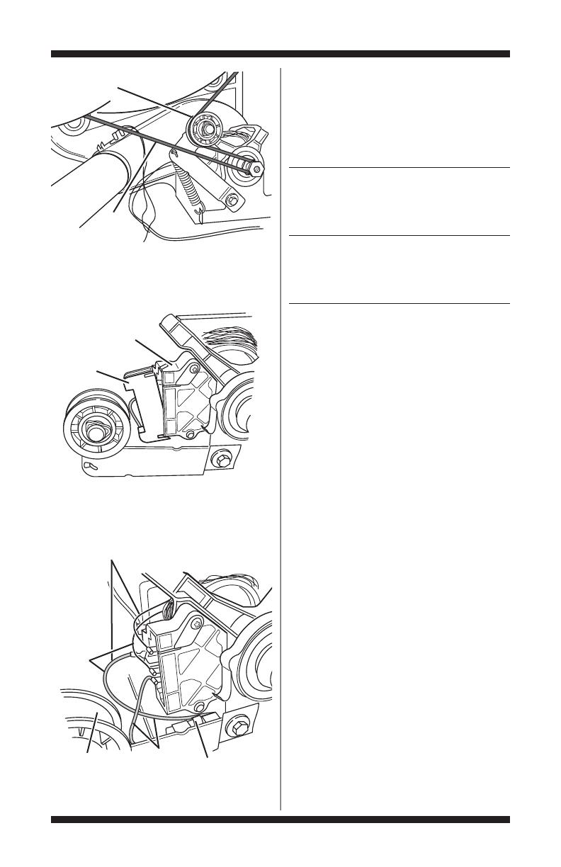
4. Check the belt switch and drive motor.Access
the belt switch and drive motor by removing the
back panel.Slowly remove the drum belt from the
spring-loaded belt switch pulley, gently letting the
belt switch pulley down. See figure 7, page 15.
COM
Neu
G
L1
L1
Masse
N
Neu
N
G
Masse
Figure 6. Power cord terminals, gas dryer.
Power Cord Plug
1
5
3
46
2
Figure 8. Remove white connector.
Drive Motor
Switch
White
Connector
FOR SERVICE TECHNICIAN ONLY - DO NOT REMOVE OR DESTROY
PAGE 15
5. Remove the white connector from the drive
motor switch. See figure 8.
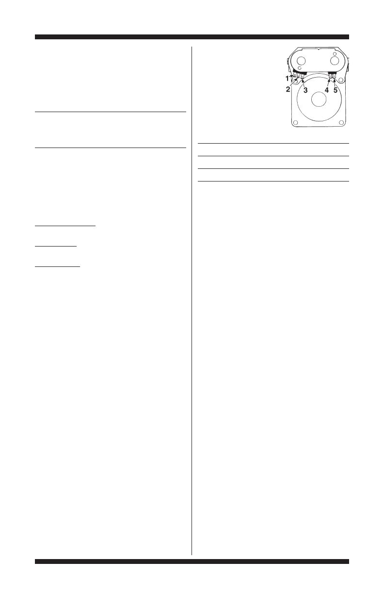
6. Using figure 9, check for the resistance values
of the motor’s Main and Start winding coils as
shown in the following table:
NOTE: Main and Start winding coils must be
checked at the motor.
Resistance Contact Points
Winding Ω of Measurement
Lt. blue wire in
back at pin 4 and
MAIN 3.0–4.0 bare copper wire
on pin 5 of black
drive motor switch
Lt. blue wire in
back at pin 4 and
START 2.4–3.4 bare copper wire
on pin 3 of black
drive motor switch
If the resistance at the motor is correct, there
is an open circuit between the motor and machine
control electronics. Check for failed belt switch.
If the Start winding is in question and the
resistance is much greater than 4 Ω, replace
the motor.
7. Check the belt switch by measuring resistance
between the two light blue wires, as shown in
figure 9,while pushing up the belt switch pulley.
If the resistance reading goes from infinity
to a few ohms as pulley arm closes the switch,
belt switch is OK. If not, replace the belt switch.
If belt switch is OK and there is still an open
circuit,check and repair the wiring harness.
8. Door Switch problems can be uncovered by
following procedure under Diagnostic Test: Door
Switch, page 5; however, if this was not done,
the following can be done without applying power
to the dryer.Connect an ohmmeter across P8-3
(neutral, white wire) and P8-4 (door, tan wire).
With the door properly closed, the ohmmeter
should indicate a closed circuit (0–2 Ω).
If not, replace the door switch assembly.
TEST #3 Heater
This test is performed when either of the
following situations occur:
✔ Dryer does not heat
✔ Heat will not shut off
This test checks the components making up the
heating circuit.The following items are part of
this system:
Figure 7. Slowly remove drum belt.
Belt Switch Pulley
Drum
Belt
1
5
3
4
6
2
Main Winding:
Lt. Blue Wire in Back
and Bare Copper Wire
Start
Winding:
Lt. Blue
Wire in
Back
and Bare
Copper
Wire
Figure 9. Main and start winding measure points
and checking the belt switch.
Lt. Blue
Wires
Belt Switch
Pulley
Belt Switch
FOR SERVICE TECHNICIAN ONLY - DO NOT REMOVE OR DESTROY
PAGE 16
Electric Gas
Part of Heating System Dryer Dryer
Harness/connection ✔✔
Heater relay ✔✔
Thermal cut-off ✔✔
Thermal fuse no ✔
High limit thermostat ✔✔
Heat element assembly ✔ no
Gas burner assembly no ✔
Centrifugal switch ✔✔
Exhaust thermistor ✔✔
Machine control ✔✔
electronics.See ESD
information, page 1.
User interface and ✔✔
housing assembly
Gas supply no ✔
Dryer does not heat:
Locate the components using figure 10.
ELECTRIC DRYER:
1. Unplug dryer or disconnect power.
2. Remove the toe panel to access the thermal
components.
3. Using an ohmmeter and referring to the wiring
diagram, measure the resistance from the red
wire terminal at the thermal cut-off to the red
wire terminal at the heater.
If the resistance is about 10 Ω,go to step 5.
If an open circuit is detected, go to step 4.
4. Visually check the wire connections to the
thermal cut-off, high limit thermostat,and heater.
If connections look good, check for continuity
across each of these components.
Replace the heater if it is electrically open.
Replace both the thermal cut-off and high limit
thermostat if either one is electrically open.
Figure 10. Thermal Components, viewed from front.
Gas Dryer
Electric Dryer
Flame
Sensor
High Limit Thermostat
Thermal
Cut-Off
Thermal Fuse
Exhaust Thermistor
Exhaust Thermistor
Thermal Fuse
High Limit Thermostat
Heater
Element
Thermal
Cut-Off

FOR SERVICE TECHNICIAN ONLY - DO NOT REMOVE OR DESTROY
PAGE 17
5. If no open circuit is detected,remove the P14
connector, then measure the resistance between
P14-3 (red-white wire) and P14-6 (red-white wire)
at the connector. See figure 15, page 23, for
connector location; and Accessing & Removing
the ElectronicAssemblies, page 21.
If 5–15 kΩ are measured, replace the
machine control electronics.
If the resistance is less than 1 kΩ, replace
the exhaust thermistor.
GAS DRYER:
1. Unplug dryer or disconnect power.
2. Remove the toe panel to access the thermal
components.
3. Perform TEST #3b, page 18. If the thermal
fuse is OK, go to step 4.
4. Perform TEST #3c, page 18. If the thermal
cut-off is OK, go to step 5.
5. Locate the high limit thermostat. See figure
10. Measure the continuity through it by
connecting the meter probes on the red wire
and blue wire terminals.
If there is an open circuit,replace the high
limit thermostat and the thermal cut-off.
Otherwise,go to step 6.
6. Perform TEST #3d, page 18. If this is OK,
replace the machine control electronics.
Heat will not shut off:
1. Unplug dryer or disconnect power.
2. Access the machine control electronics.
Remove the P14 connector, then measure the
resistance between P14-3 (red-white wire) and
P14-6 (red-white wire) at the connector. See
figure 15, page 23 for connector location; and
Accessing & Removing the Electronic Assemblies,
page 21.
If 5–15 kΩ are measured, replace the
machine control electronics.
If the resistance is greater than 20 kΩ,
replace the exhaust thermistor.
TEST #3a Exhaust Thermistor
The machine control electronics monitors
the exhaust temperature using the exhaust
thermistor, and cycles the heater relay on
and off to maintain the desired temperature.
Begin with an empty dryer and a clean
lint screen.
1. Plug in dryer or reconnect power.
2. Start theTimed Dry cycle.
3. If after 60 seconds, f3 e1 or f3 e2 flashes
in the display (on models with seven segment
display) or the WET indicator flashes F3E1 or
F3E2 (on models without seven segment display)
and the dryer shuts off, the thermistor or wire
harness is either open or shorted.
Unplug dryer or disconnect power.
Check wire connections at the machine control
electronics and thermistor. See Accessing &
Removing the ElectronicAssemblies, page 21, and
for thermistor location,see figure 10, page 16.
If wire connections are good,remove the two
wiresfrom the thermistor and replacethe thermistor.
Reassemble all parts and panels.
Plug in dryer or reconnect power.
4. If f3 e1 or f3 e2 does not flash in the display
(on models with seven segment display) or the
WET indicator does not flash F3E1 or F3E2 (on
models without seven segment display), the
connections to the thermistor are good.Therefore,
check the exhaust temperature value at any or
all of the temperature levels in question, using
the Timed Dry cycle,and the following process:
Hold a glass bulb thermometer capable of
reading from 90° to 180°F (32° to 82°C) in the
center of the exhaust outlet.The correct exhaust
temperatures are as follows:
EXHAUST TEMPERATURES
Temperature Heat Turns Off* Heat Turns On
Setting °F (°C) °F (°C)
High 155°±5° (68°±3°) 10–15°
Med High 150°±5° (66°±3°) (6–8°)
(Maytag only) below
Medium 140°±5° (60°±3°) the heat
Low 125°±5° (52°±3°) turn off
Extra Low 105°±5° (41°±3°) temperature
* The measured overshoot using the glass bulb
thermometer in the exhaust outlet can be 30°F
(17°C) higher.
5. If the exhaust temperature is not within
specified limits, remove the P14 connector, then
measure the resistance between P14-3 (red-
white wire) and P14-6 (red-white wire) at the
connector. See figure 15, page 23 for connector
location; and Accessing & Removing the
ElectronicAssemblies, page 21.
NOTE: All thermistor resistance measurements
must be made while dryer is unplugged or
disconnected from power.
FOR SERVICE TECHNICIAN ONLY - DO NOT REMOVE OR DESTROY
PAGE 18
The following table gives temperatures and their
associated resistance values.
EXHAUST THERMISTOR RESISTANCE
Res. Res.
Temp Range Temp Range
°F (°C) kΩ °F (°C) kΩ
50° (10°) 19.0–22.0 80° (27°) 8.5–10.5
60° (16°) 14.8–16.8 90° (32°) 6.8–8.8
70° (21°) 11.5–13.5 100° (38°) 5.0–7.0
If the thermistor resistance does not agree
with table,replace the exhaust thermistor.
If the thermistor resistance checks agree
with the measurements in the table, replace
the machine control electronics.
TEST #3b Thermal Fuse
ELECTRIC DRYER: The thermal fuse is wired
in series with the dryer drive motor.
GAS DRYER:
The thermal fuse is wired in series
with the dryer gas valve.
ALL DRYERS:
1. Unplug dryer or disconnect power.
2. Access the thermal fuse by first removing
the toe panel.For thermal fuse location, see
figure 10, page 16.
3. Using an ohmmeter, check the continuity
across the thermal fuse. See figure 10 for location.
If the ohmmeter indicates an open circuit,
replace the failed thermal fuse.
TEST #3c Thermal Cut-Off
If the dryer does not produce heat, check the
status of the thermal cut-off.
1. Unplug dryer or disconnect power.
2. Access the thermal cut-off by first removing
the toe panel.
3. Using an ohmmeter, check the continuity
across the thermal cut-off.See figure 10, page
16, for location.
If the ohmmeter indicates an open circuit,
replace the failed thermal cut-off and high limit
thermostat. In addition, check for blocked or
improper exhaust system, or failed heat element
(electric dryer).
TEST #3d Gas Valve, Gas Dryer Only
1. Unplug dryer or disconnect power.
2. Access the gas valve by removing the
toe panel.
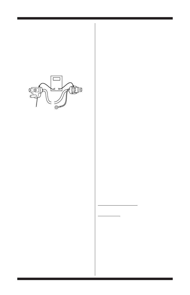
3. Use an ohmmeter to
determine if a gas valve
coil has failed. Remove
harness plugs. Measure
resistance across terminals.
Readings should match
those shown in the
following chart.If not,
replace coil.
Terminals Resistance (Ω)
1 to 2 1365 ± 25
1 to 3 560 ± 25
4 to 5 1220 ± 50
IMPORTANT: Be sure all harness wires are
looped back through the strain relief after
checking or replacing coils.
TEST #4 Moisture Sensor
NOTE: This test is started with the dryer
completely assembled.
This test is performed when an automatic cycle
stops too soon, or runs much longer than expected.
NOTE: Dryer will shut down automatically
after 2-1/2 hours.
The following items are part of this system:
Harness/connection
Metal sensor strips
Machine control electronics.
See ESD information, page 1.
1. Enter Service Diagnostic mode and select the
User Interface/Control System test.See procedure
on page 5.
2. Open the dryer door.The dryer should beep
and an alphanumeric number should be displayed
(on models with seven segment display) or the
TEMP indicators should change (on models without
seven segment display).
3. Locate the two metal sensor strips on the
face of the lint screen housing. Bridge these strips
with a wet cloth or finger.
If a beep tone is heard and an alphanumeric
number is displayed on the console (on models
with seven segment display) or the TEMP and
STATUS indicators change (on models without
seven segment display),the sensor passed
the test.Go to step 9.
If a beep tone is not heard, or a continuous
beep tone is heard before bridging the moisture
strips, continue with step 4.
NOTE: Overdrying may be caused by a short
circuit in the sensor system.
FOR SERVICE TECHNICIAN ONLY - DO NOT REMOVE OR DESTROY
PAGE 19
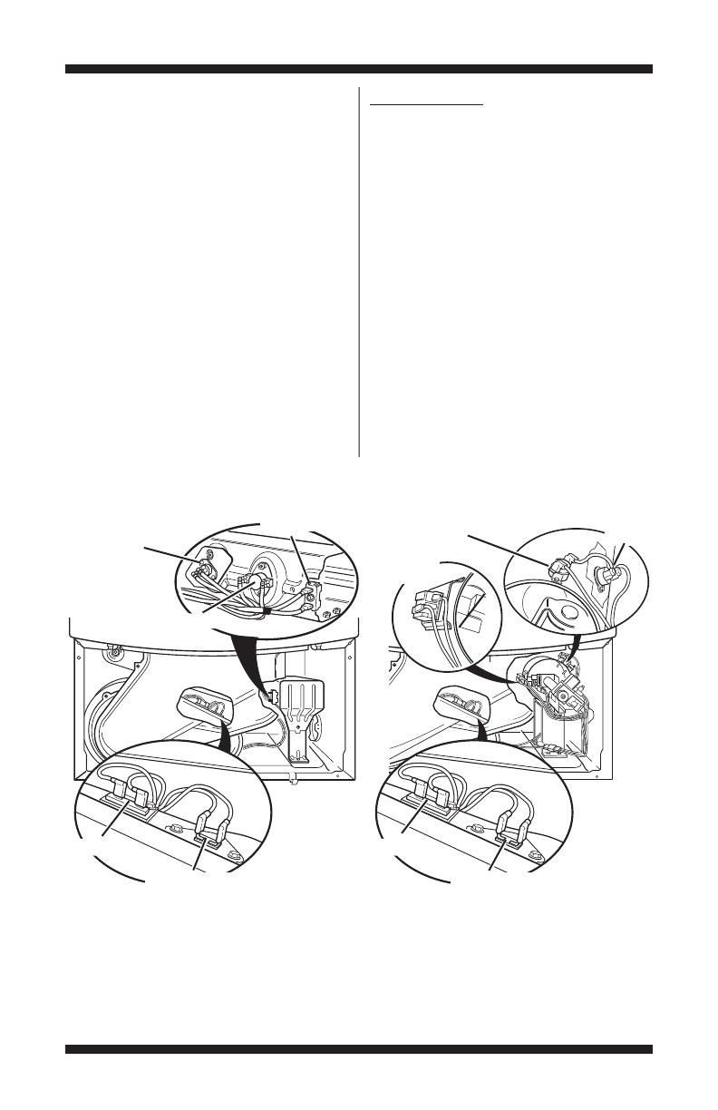
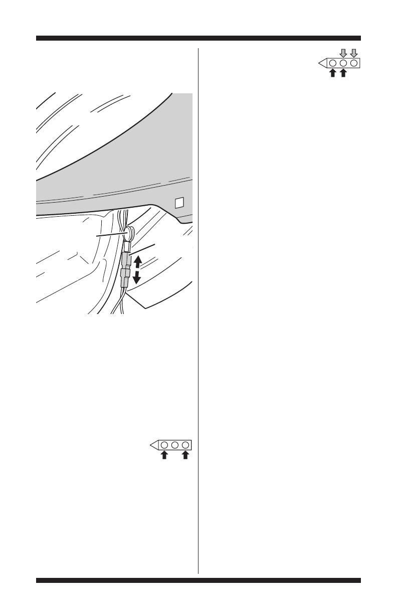
4. Unplug dryer or disconnect power.
5. Access the moisture sensor wires by removing
the toe panel.Disconnect the sensor wires from
the harness. See figure 11.
6. Access the machine control electronics.See
Accessing & Removing the Electronic Assemblies,
page 21. Remove connector P13 from the circuit
board.Check the main harness connections
between the sensor harness and machine control
for a short or open circuit.
Replace the main harness, if necessary.
If harness is OK,continue with step 7.
7. Measure the resistance
across the outermost
contacts of the cable that
includes the two red MOVs.
If a small resistance is measured, check for
debris across moisture strips inside the drum;
clean if debris is present. If debris is not present,
replace sensor harness.
If a small resistance is not measured, continue
with step 8.
8. Measure the resistance across
each of the outermost contacts
and the center terminal (ground
connection).
If a resistance less than infinity is measured,
replace the sensor harness.
9. If moisture sensor diagnostic test passes, check
the thermistor:PerformTEST #3a,page 17.
If the problem persists after replacing the
moisture sensor and thermistor,replace the
machine control electronics.
TEST #4a Adjusting
Customer-Focused Drying Modes
NOTE: If the customer complains about the
clothes being consistently damp on automatic
cycles and the moisture sensor passed TEST #4,
step 3,the total auto dry time can be changed
by choosing one of 3 different Customer-Focused
drying modes:
1 = standard auto cycle
2 = 15% more drying time
3 = 30% more drying time
1. Be sure the dryer is in standby mode (plugged
in with all indicators off, or with only the DONE
[on some models] or COMPLETE [on some
models] indicator on).
2. Activate the Customer-Focused Drying Mode
by pressing and holding the TEMP button for
more than 6 seconds.
3. On models with seven segment display, the
dryer will beep and cf will be displayed for 1
second followed by the current drying setting.
On models without seven segment display,the
dryer will beep and the current drying mode
will be seen on the STATUS indicators.The factory
default value is“1”.
4. To select a different drying mode, press
the TEMP button again. On models with seven
segment display, the dryer display will flash
and show 2, 3, or 1. On models without seven
segment display, STATUS indicators will indicate
the current selected drying mode.
On models without seven segment display:
1 = WET indicator lit constantly or flashing
2 = WET and DAMP indicators lit constantly
or flashing
3 = WET, DAMP, and COOL DOWN indicators
lit constantly or flashing
NOTE: On all models, while cycling through the
settings, the current setting will not flash, but the
other settings will.
FRONT
Drum
Harness
Connection
MOVs
(Metal Oxide
Varistors)
Blower
Housing
Figure 11. Disconnect sensor from wire
harness.

FOR SERVICE TECHNICIAN ONLY - DO NOT REMOVE OR DESTROY
PAGE 20
5. With the desired drying mode shown, press
the START button to save the drying mode and
exit diagnostics (the START button in this mode
does not start a drying cycle).The result will be
stored in EEPROM of the control board, and will
be retained after a power loss.
6. Press the POWER button at any time to cancel
changes and exit from this mode.
TEST #5 Buttons and Indicators
This test is performed when any of the following
situations occurs during the Console Buttons and
Indicators Diagnostic Test,page 5:
✔ None of the indicators light up
✔ No beep sound is heard
✔ Some buttons do not light indicators
None of the indicators light up:
1. See Diagnostic Guide/Before Servicing...
on page 1.
2. Perform TEST #1, page 12, to verify supply
connections.
3. Perform steps inAccessing & Removing the
ElectronicAssemblies, page 21, and visually
check that the P5 connector is inserted all the
way into the machine control electronics.
4. Visually check that the user interface
and housing assembly is properly inserted
into the front console.
5. If both visual checks pass, replace the
user interface and housing assembly.
6. Reassemble all parts and panels.
7. Plug in dryer or reconnect power.
8. Activate the Service Diagnostic mode per
procedure on page 2. Then activate the User
Interface/Control System test and verify the repair
by completing the Buttons and Indicators test per
procedures on page 5.
9. If indicators still do not light, the machine
control electronics has failed:
Unplug dryer or disconnect power.
Replace the machine control electronics.
Reassemble all parts and panels.
Plug in dryer or reconnect power.
Activate the Service Diagnostic mode per
procedure on page 2.Then activate the User
Interface/Control System test and verify the repair
by completing the Buttons and Indicators test per
procedures on page 5.
No beep sound is heard:
1. Perform steps in Accessing & Removing the
ElectronicAssemblies, page 21, and visually
check that the P5 connector is inserted all the
way into the machine control electronics.
If visual check passes,replace the user
interface and housing assembly.
2. Reassemble all parts and panels.
3. Plug in dryer or reconnect power.
4. Activate the Service Diagnostic mode per
procedure on page 2. Then activate the User
Interface/Control System test and verify the repair
by completing the Buttons and Indicators test per
procedures on page 5.
5. If replacing the user interface and housing
assembly failed:
Unplug dryer or disconnect power.
Replace the machine control electronics.
Reassemble all parts and panels.
Plug in dryer or reconnect power.
Activate the Service Diagnostic mode per
procedure on page 2. Then activate the User
Interface/Control System test and verify the repair
by completing the Buttons and Indicators test per
procedures on page 5.
Some buttons do not light indicators:
1. Perform steps in Accessing & Removing the
ElectronicAssemblies, page 21, and visually
check that the user interface and housing
assembly is properly inserted into the front console.
If visual check passes,replace the user
interface and housing assembly.
2. Reassemble all parts and panels.
3. Plug in dryer or reconnect power.
4. Activate the Service Diagnostic mode per
procedure on page 2. Then activate the User
Interface/Control System test and verify the repair
by completing the Buttons and Indicators test per
procedures on page 5.
TEST #6 Door Switch
Perform steps under Activating the Service
Diagnostic Mode,page 2, and activate the User
Interface/Control System test.Then perform the
Door Switch Diagnostic test,page 5. Functionality
is verified with a beep each time the door is closed
and opened,and, on models with seven segment
display, an alphanumeric number appears in the
display (i.e., 05).On models without seven
segment display, theTEMP indicators display the
Control Software ID along with the WET or DONE
(COMPLETE on some models) indicator
illuminating to indicate fuel type.
/