Makita DUP361 User manual

Category
Power tools
Type
User manual

This manual is also suitable for

Makita DUP361 is powered by a 36V battery and can cut branches up to 33 mm thick. It's lightweight, weighing only 0.77-0.82 kg, and has a compact design for easy maneuvering. It's ideal for pruning twigs and branches in gardening and landscaping tasks, and features a sharp blade for precise and efficient cutting.

Makita DUP361 is powered by a 36V battery and can cut branches up to 33 mm thick. It's lightweight, weighing only 0.77-0.82 kg, and has a compact design for easy maneuvering. It's ideal for pruning twigs and branches in gardening and landscaping tasks, and features a sharp blade for precise and efficient cutting.

INSTRUCTION MANUAL
Battery Powered Pruning Shears
DUP361
DUP362
ENGLISH: Original instructions
Read before use.
2 ENGLISH
SPECIFICATIONS
Model: DUP361 DUP362
Max. cutting capacity 33 mm
Overall length (shears part) 305 mm
Rated voltage D.C.36 V
Net weight (shears part) 0.77 - 0.82 kg
• Duetoourcontinuingprogramofresearchanddevelopment,thespecicationshereinaresubjecttochange
without notice.
• Specicationsmaydifferfromcountrytocountry.
Weight, the shears part only, according to EPTA-Procedure 01/2014
Applicable battery cartridge and charger
Battery cartridge BL1815N / BL1820 / BL1820B / BL1830 / BL1830B / BL1840 /
BL1840B / BL1850 / BL1850B / BL1860B
Charger DC18RC / DC18RD / DC18RE / DC18SD / DC18SE / DC18SF
Some of the battery cartridges and chargers listed above may not be available depending on your region of residence.
WARNING: Only use the battery cartridges and chargers listed above. Use of any other battery cartridges
andchargersmaycauseinjuryand/orre.
Symbols
The followings show the symbols used for the equipment.
Be sure that you understand their meaning before use.
Read instruction manual.
Do not expose to moisture.
Danger;beawareofthrownobjects.
Keep bystanders away.
Ni-MH
Li-ion
Only for EU countries
Do not dispose of electric equipment or
battery pack together with household waste
material!
In observance of the European Directives,
on Waste Electric and Electronic
Equipment and Batteries and Accumulators
and Waste Batteries and Accumulators
and their implementation in accordance
with national laws, electric equipment and
batteries and battery pack(s) that have
reached the end of their life must be col-
lected separately and returned to an envi-
ronmentally compatible recycling facility.
Intended use
The tool is intended for pruning twigs or branches.
Noise
The typical A-weighted noise level determined accord-
ing to EN50636-2-94:
Model DUP361
Sound pressure level (L
pA
) : 70 dB(A) or less
Uncertainty (K) : 3.2 dB(A)
Model DUP362
Sound pressure level (L
pA
) : 70 dB(A) or less
Uncertainty (K) : 1.4 dB(A)
The noise level under working may exceed 80 dB (A).
WARNING: Wear ear protection.
Vibration
The vibration total value (tri-axial vector sum) deter-
mined according to EN50636-2-94:
Model DUP361
Vibration emission (a
h
) : 2.5 m/s
2
or less
Uncertainty (K) : 1.5 m/s
2
Model DUP362
Vibration emission (a
h
) : 2.5 m/s
2
or less
Uncertainty (K) : 1.5 m/s
2
NOTE: The declared vibration total value(s) has been
measured in accordance with a standard test method
and may be used for comparing one tool with another.
NOTE: The declared vibration total value(s) may also
be used in a preliminary assessment of exposure.
WARNING: The vibration emission during
actual use of the power tool can differ from the
declared value(s) depending on the ways in which
the tool is used especially what kind of workpiece
is processed.
WARNING: Be sure to identify safety mea-
sures to protect the operator that are based on an
estimation of exposure in the actual conditions of
use (taking account of all parts of the operating
cycle such as the times when the tool is switched
off and when it is running idle in addition to the
trigger time).
3 ENGLISH
EC Declaration of Conformity
For European countries only
The EC declaration of conformity is included as Annex A
to this instruction manual.
Pruning shears safety warnings
WARNING: Read all safety warnings and
all instructions. Failure to follow the warnings and
instructionsmayresultinelectricshock,reand/or
seriousinjury.
Save all warnings and instruc-
tions for future reference.
The term "power tool" in the warnings refers to your
mains-operated (corded) power tool or battery-operated
(cordless) power tool.
1.
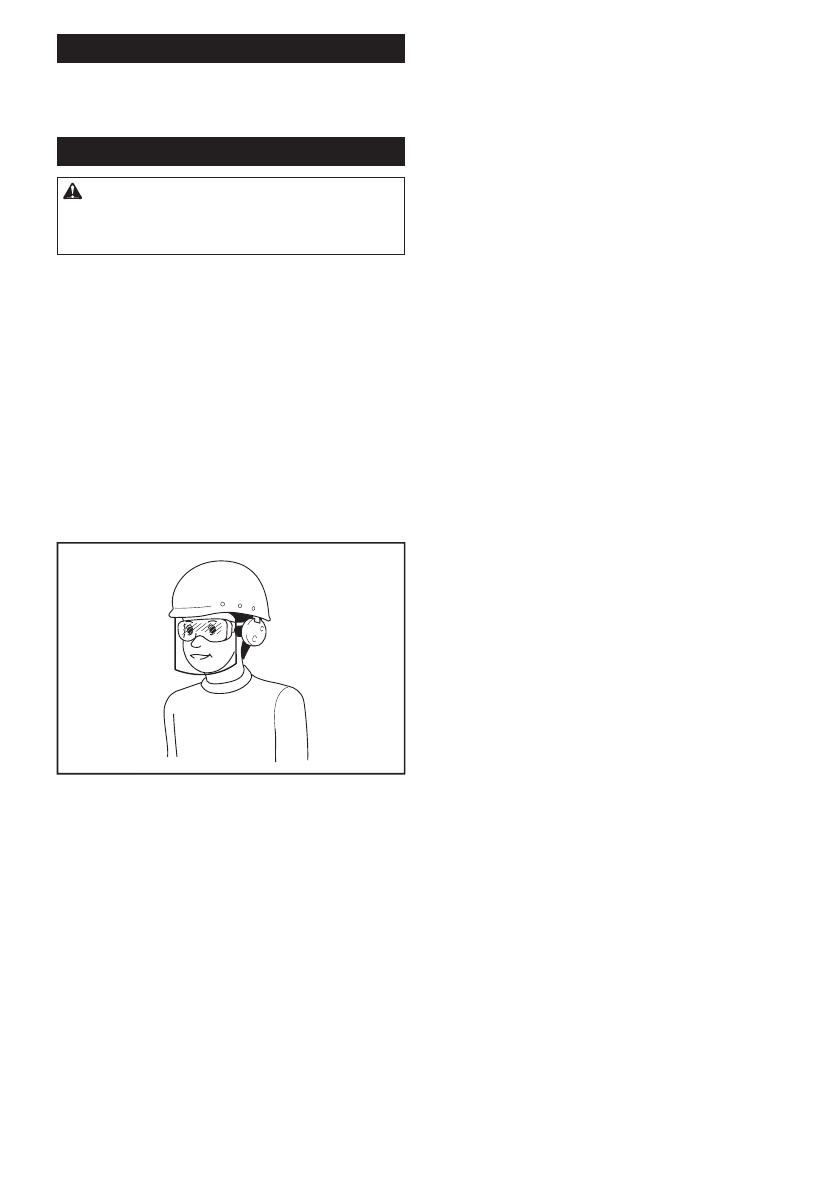
Use personal protective equipment. Always wear eye
protection. Protective equipment such as a dust mask,
non-skid safety shoes, hard hat or hearing protection used
forappropriateconditionswillreducepersonalinjuries.
2.
Always wear protective goggles to protect your eyes
from injury when using power tools.The goggles
must comply with ANSI Z87.1 in the USA, EN 166 in
Europe, or AS/NZS 1336 in Australia/New Zealand. In
Australia/New Zealand, it is legally required to wear
a face shield to protect your face, too.
It is an employer's responsibility to enforce
the use of appropriate safety protective equip-
ments by the tool operators and by other per-
sons in the immediate working area.
3.
Prevent unintentional starting. Ensure the switch is in
the off-position before connecting to power source and/
or battery pack, picking up or carrying the tool. Carrying
powertoolswithyourngerontheswitchorenergising
power tools that have the switch on invites accidents.
4. Dress properly. Do not wear loose clothing or
jewellery. Keep your hair, clothing, and gloves
away from moving parts.Looseclothes,jewel-
lery or long hair can be caught in moving parts.
5. This tool is for pruning branches. Do not use it
foranyjobexceptthatforwhichitisintended.
6. Never allow children, persons with reduced
physical, sensory or mental capabilities or
lack of experience and knowledge or people
unfamiliar with these instructions to use the
tool. Local regulations may restrict the age of
the operator.
7. Children should be supervised to ensure that
they do not play with the appliance.
8. Never operate the tool while people, especially
children, or pets are nearby.
9. Do not overreach and keep balance at all
times. Always be sure of footing on slopes and to
walk, never run.
10. Do not touch moving hazardous parts before
the tool is disconnected from the mains and/or
the battery pack is removed from the tool.
11. Always wear substantial footwear and long
trousers while operating the tool.
12. Disconnect the supply and/or remove the
battery pack from the tool:
whenever the tool is left by the user,
before clearing a blockage,
before checking, cleaning or working on the
tool,
• afterstrikingaforeignobjecttoinspectthe
tool for damage,
if the tool starts to vibrate abnormally, for
immediately check.
13. Never operate the tool with defective guards
or shields, or without safety devices, or if the
cord is damaged or worn.
14. Avoid using the tool in bad weather conditions
especially when there is a risk of lightning.
15. Don’t use the tool or perform battery charging
operations in the rain.
16. Don’t leave the tool in rain or wet locations.
17. Be careful not to catch foreign matter between
the blades.Ifthebladesarejammedwithforeign
matter, immediately switch off the tool and discon-
nect the battery from the tool. Then remove the
foreign matter from the blades.
18. Never hold the branch you are pruning with
your free hand. Keep your free hand away from
the cutting area. Never touch the blades, they are
very sharp and you may cut yourself.
19. Don’t force the tool to make it cut. You could
slipandinjureyourselforcutsomethingelse
unintentionally.
20.
Avoid cutting electrical wires that may be hidden.
21.
Always check the blades carefully before operation.
22. Handle the blades with extreme care to prevent
cuts or injury from the blades.
23. Disconnect the battery from the tool after each
use and before attempting to perform inspec-
tion or maintenance.
24. When not in use, always keep the tool in its
holster.
Battery tool use and care
1. Avoid dangerous environment. Don't use the
tool in damp or wet locations or expose it to
rain. Water entering the tool will increase the
risk of electric shock.
2. Recharge only with the charger specied by
the manufacturer. A charger that is suitable for
onetypeofbatterypackmaycreateariskofre
when used with another battery pack.
3. Use power tools only with specically desig-
nated battery packs. Use of any other battery
packsmaycreateariskofinjuryandre.
4 ENGLISH
4. When battery pack is not in use, keep it away
from other metal objects, like paper clips,
coins, keys, nails, screws or other small metal
objects, that can make a connection from one
terminal to another. Shorting the battery termi-
nalstogethermaycauseburnsorare.
5. Under abusive conditions, liquid may be
ejected from the battery; avoid contact. If con-
tact accidentally occurs, ush with water. If
liquid contacts eyes, additionally seek medical
help.Liquidejectedfromthebatterymaycause
irritation or burns.
6. Do not dispose of the battery(ies) in a re. The
cell may explode. Check with local codes for
possible special disposal instructions.
7. Do not open or mutilate the battery(ies).
Released electrolyte is corrosive and may
cause damage to the eyes or skin. It may be
toxic if swallowed.
8. Do not charge battery in rain, or in wet
locations.
Service
1. Have your power tool serviced by a qualied
repair person using only identical replacement
parts. This will ensure that the safety of the power
tool is maintained.
2. Follow instruction for lubricating and chang-
ing accessories.
3. Keep handles dry, clean and free from oil and
grease.
WARNING: DO NOT let comfort or familiarity
with product (gained from repeated use) replace
strict adherence to safety rules for the subject
product. MISUSE or failure to follow the safety
rules stated in this instruction manual may cause
serious personal injury.
Important safety instructions for
battery cartridge
1.
Before using battery cartridge, read all instruc-
tions and cautionary markings on (1) battery
charger, (2) battery, and (3) product using battery.
2. Do not disassemble battery cartridge.
3. If operating time has become excessively
shorter, stop operating immediately. It may
result in a risk of overheating, possible burns
and even an explosion.
4. If electrolyte gets into your eyes, rinse them
out with clear water and seek medical atten-
tion right away. It may result in loss of your
eyesight.
5. Do not short the battery cartridge:
(1) Do not touch the terminals with any con-
ductive material.
(2) Avoid storing battery cartridge in a con-
tainer with other metal objects such as
nails, coins, etc.
(3) Do not expose battery cartridge to water
or rain.
A battery short can cause a large current
ow, overheating, possible burns and even a
breakdown.
6. Do not store the tool and battery cartridge in
locations where the temperature may reach or
exceed 50 °C (122 °F).
7. Do not incinerate the battery cartridge even if
it is severely damaged or is completely worn
out. The battery cartridge can explode in a re.
8. Be careful not to drop or strike battery.
9. Do not use a damaged battery.
10. The contained lithium-ion batteries are subject
to the Dangerous Goods Legislation require-
ments.
For commercial transports e.g. by third parties,
forwarding agents, special requirement on pack-
aging and labeling must be observed.
For preparation of the item being shipped, consult-
ing an expert for hazardous material is required.
Please also observe possibly more detailed
national regulations.
Tape or mask off open contacts and pack up the
battery in such a manner that it cannot move
around in the packaging.
11. Follow your local regulations relating to dis-
posal of battery.
12. Use the batteries only with the products
specied by Makita. Installing the batteries to
non-compliantproductsmayresultinare,exces-
sive heat, explosion, or leak of electrolyte.
SAVE THESE INSTRUCTIONS.
CAUTION: Only use genuine Makita batteries.
Use of non-genuine Makita batteries, or batteries that
have been altered, may result in the battery bursting
causingres,personalinjuryanddamage.Itwill
also void the Makita warranty for the Makita tool and
charger.
Tips for maintaining maximum
battery life
1. Charge the battery cartridge before completely
discharged. Always stop tool operation and
charge the battery cartridge when you notice
less tool power.
2. Never recharge a fully charged battery car-
tridge. Overcharging shortens the battery
service life.
3. Charge the battery cartridge with room tem-
perature at 10 °C - 40 °C (50 °F - 104 °F). Let
a hot battery cartridge cool down before
charging it.
4. Charge the battery cartridge if you do not use
it for a long period (more than six months).
N Mark
The N Mark is a trademark or registered trademark of
NFC Formula, Inc. in USA and other countries in the
world.
(This tool is equipped with an NFC receiver only for
a service purpose used by authorized/factory service
centers.)
5 ENGLISH
PARTS DESCRIPTION
1
4
2
10
3
7
9
11
8
5
6
1 Harness * 2 Back pack 3 Switch box 4 Pilot lamp (red)
5 Pilot lamp (green) 6 I/O switch 7 Holster 8 Cord holder
9 Connection cord 10 Shears 11 Switch trigger - -
* The shape may differ depending on the tool variation.
6 ENGLISH
FUNCTIONAL
DESCRIPTION
CAUTION: Always be sure that the tool is
switched off and the battery cartridge is removed
before adjusting or checking function on the tool.
Removing or installing battery cartridge
CAUTION: Always switch off the tool before
installing or removing of the battery cartridge.
CAUTION: Hold the tool and the battery car-
tridge rmly when installing or removing battery
cartridge. Failure to hold the tool and the battery
cartridgermlymaycausethemtoslipoffyourhands
and result in damage to the tool and battery cartridge
andapersonalinjury.
1
2
3
4
3
►1. Red indicator 2. Button 3. Battery cartridge
4. Battery holder
To remove the battery cartridge, slide it from the tool
while sliding the button on the front of the cartridge.
To install the battery cartridge, align the tongue on the
battery cartridge with the groove in the housing and slip
it into place. Insert it all the way until it locks in place
with a little click. If you can see the red indicator on the
upper side of the button, it is not locked completely.
CAUTION: Always install the battery cartridge
fully until the red indicator cannot be seen. If not,
itmayaccidentallyfalloutofthetool,causinginjuryto
you or someone around you.
CAUTION: Do not install the battery cartridge
forcibly. If the cartridge does not slide in easily, it is
not being inserted correctly.
NOTE: The tool does not work with only one battery
cartridge.
Tool / battery protection system
The tool is equipped with a tool/battery protection
system. This system automatically cuts off power to
the motor to extend tool and battery life. The tool will
automatically stop during operation if the tool or battery
is placed under one of the following conditions. In some
conditions, the lamps on the switch box lights up.
Overload protection
When the tool is operated in a manner that causes it to
draw an abnormally high current, the tool automatically
stops without any indication. In this situation, turn the
tool off and stop the application that caused the tool to
become overloaded. Then turn the tool on to restart.
Overheat protection
When the tool is overheated, the tool stops automatically,
and the green lamp on the switch box blinks. In this situa-
tion, let the tool cool down before turning the tool on again.
Overdischarge protection
When the battery capacity becomes low, the tool stops
automatically. And the red lamp on the switch box lights
up or blinks. If the product does not operate even when
the switches are operated, remove the batteries from
the battery holder and charge the batteries.
Indicating the remaining battery
capacity
Only for battery cartridges with the indicator
1
2
►1. Indicator lamps 2. Check button
Press the check button on the battery cartridge to indi-
cate the remaining battery capacity. The indicator lamps
light up for a few seconds.
Indicator lamps Remaining
capacity
Lighted Off Blinking
75% to 100%
50% to 75%
25% to 50%
0% to 25%
Charge the
battery.
The battery
may have
malfunctioned.
7 ENGLISH
NOTE: Depending on the conditions of use and the
ambient temperature, the indication may differ slightly
from the actual capacity.
Switch action
CAUTION: Before connecting the battery to
the shears, always check to see that the switch
trigger actuates properly and returns to the “OFF”
position when released.
CAUTION: When not operating the tool,
always make sure that the I/O switch is on the "O"
side.
CAUTION: Do not press the I/O switch to the
“I” (on) position while pulling the switch trigger.
The blade closes slightly and it may cause personal
injury.
To turn on the tool, perform as follows:
1. Connect the switch box, connection cord, and
shears. (Refer to “Installing the connection cord”.)
2. Holdtheshearsrmly,andpresstheI/Oswitchto
the “I” (on) position. The green pilot lamp lights up.
1
2
3
►1. I/O switch 2. Pilot lamp (green) 3. Pilot lamp (red)
3. The shear blades are locked-mode when the I/O
switch is on. To release the lock, pull the switch trigger
two times. The upper shear blade opens automatically.
4. To close the shear blade, pull the switch trigger.
1
►1. Switch trigger
Auto locked-mode and shut-off
mode shift
For safety reasons, the tool shifts into locked-mode or
shut-off mode automatically if the tool is left untouched
for a certain period of time.
After 5 minutes: The tool shifts into locked-mode. Pull
the switch trigger two times to release the lock.
After 15 minutes: The tool is shift into shut-off mode, and the
green pilot lamp turns off. Press the I/O switch to the “O” (off)
position once, and press the I/O switch to the “I” (on) position
again, then pull the switch trigger two times to release the lock.
Opening angle selector lever
1
►1. Opening angle selector lever
By tilting the opening angle selector lever to the left
side, you can open the upper shear blade wider.
Tolimittheuppershearbladeopeningangle,rstpull
the switch trigger fully, and then return the opening
angle selector lever to straight position.
Cutting depth adjustment
CAUTION: Do not let your hands or part of
body close to the shear blades. Otherwise per-
sonal injury may result.
Aftersharpeningorreplacingtheshearblade,adjust
cutting depth if necessary.
Turn on the tool, and pull the switch trigger two times to open the
shear blades, and then press the I/O switch to the “O” (off) position.
Todeepenthecuttingdepth,turnthecuttingdepthadjustingscrew
clockwise with the hex wrench. And to make the cutting depth shal-
lower,turnthecuttingdepthadjustingscrewcounterclockwise.
1
►1.Cuttingdepthadjustingscrew
8 ENGLISH
NOTE:Checkthecuttingdepthafteradjustment.If
the cutting depth is too shallow, the branch may not
cut fully.
Pilot lamps on the switch box
1
2
3
►1. I/O switch 2. Pilot lamp (green) 3. Pilot lamp (red)
The green and red lamps indicate as follows:
(On:
Off: Blinking: )
Green lamp lights up: the tool is turned on.
Green Red
Green lamp and red lamp light up: if you insert the
battery to the battery holder when I/O switch is “I”
(on) position, both of the lamps light up and the
blade does not move though you pull the switch
trigger. In this situation, press the I/O switch to the
“O” (off) position once, and press the I/O switch to
the “I” (on) position again.
Green Red
Green lamp blinks: the tool is overheated. Let the
tool cool down before turning the tool on again.
Green Red
Green lamp lights up and red lamp blinks or lights
up:batteryisloworalmostat.Chargethebatter-
ies. When either of the battery becomes low, the
red lamp blinks even one of the batteries is full.
Green Red
Green lamp and red lamp blink alternately: the tool
detects breaking of wire. Check the connection
cord for loose connection with the switch box and
the shears. If the lamps still blink alternately, stop
using the tool immediately, disconnect the connec-
tion cord, remove the battery, and ask your local
authorized service center for repair.
Lamps blink alternately
ASSEMBLY
CAUTION: Always be sure that the tool is
switched off and the battery cartridge is removed
before carrying out any work on the tool.
Installing the battery holder into the
backpack
1
2
3
►1. Clamp 2. Battery holder 3. Strap
1. Pass the switch box through the opening (either
right or left) of the back pack.
2. Pass the clamp through the square hole of the bat-
tery holder, and secure the battery holder with the strap.
Make sure that the battery holder sits in the backpack
rmly.
Installing the holster
1
2
►1. Holster 2. Strap
Pass the belt of the lower buckle through the opening of
the holster.
9 ENGLISH
Adjusting the harness
Adjusttheharnessasfollows:
1. Closeandlockthelowerbuckle,andadjustitsbelt
length.
1
►1. Lower buckle
2. Adjusttheshoulderstraplength.
3. Adjustthepositionoftheupperbuckle.Closeand
locktheupperbuckleandadjustitsbeltlength.
1
►1. Upper buckle
CAUTION: In case of emergency, quickly
open the lower buckle and upper buckle, loosen
shoulder straps, and set down the backpack.
Installing the connection cord
CAUTION: Always make sure that the switch
box's I/O switch is on the "O" side before attach-
ing the connection cord.
CAUTION: Do not operate the tool if the con-
nection cord is damaged.
NOTICE: Do not abuse the connection cord. Do not
carry the tool by pulling the connection cord. Keep the
connection cord away from heat, oil, or sharp edges.
Otherwise the connection cord may be damaged.
Attach the connection cord with the switch box and the
shears as follows:
1. First, align the triangular marks of the male plug
of the connection cord with the triangular mark of the
female connector of the switch box. Push in the plug of
the connection cord to the connector of the switch box.
Then, align the marking on the coupling with the trian-
glar marks, and push in and turn the coupling to tighten.
2
1
4
1
3
5
►1. Triangular mark 2. Connection cord 3. Switch box
4. Marking on coupling 5. Coupling
NOTICE: Turn the coupling and align the marking
onthecouplingwiththetriangularmarksrstwhen
disconnecting the connection cable.
10 ENGLISH
2. Hang the switch box on the waist belt or upper
belt.
3. Push the connection cord into the loop of the cord
holder.
Hang the cord holder on either the upper belt or the
waist belt on which the switch box is not hung.
The cord holder prevents the connection cord from dan-
gling around your body, and also the cord holder can
prevent the connection cord from being cut by mistake.
NOTICE: Do not hang anything other than the
connection code on the cord holder. Otherwise the
code holder may be broken.
NOTICE: Do not force the cord holder opening.
Otherwise it may result in deformation or breakage of
the code holder.
4. Put the arm band on your arm. And slip the con-
nection cord through the arm band.
1
►1. Arm band
11 ENGLISH
5.
First, align the triangular marks of the female socket of the
connection cord with the triangular mark of the male connector of
the shears. Push in the socket of the connection cord to the con-
nector of the shears. Then, align the marking on the coupling with
the trianglar marks, and push in and turn the coupling to tighten.
2
1
4
1
3
5
►1. Triangular mark 2. Connection cord 3. Shears
4. Marking on coupling 5. Coupling
NOTICE: Turn the coupling and align the marking
onthecouplingwiththetriangularmarksrstwhen
disconnecting the connection cable.
Putting shears in the holster
Keep pulling the switch trigger to close the shear blades, and press
the I/O switch to "O" side to turn off the tool. Then put the shears
into the holster and hold the shears with the strap of the holster.
OPERATION
CAUTION: Always hold the tool rmly. And
keep rm footing.
CAUTION: Do not put any of your body parts
near to the blades during operation.
CAUTION:
Before use, inspect if the blades,
blade bolts or other parts are not worn or damaged.
Replace worn or damaged parts for safe operation.
NOTICE: If the blade is stuck in a branch during
operation, do not twist the blade. In that situation, turn
off the tool and pull the blades straight out slowly from
the branch. Otherwise the blade may be damaged.
NOTICE:
In case you cut too thick branch or something too
hard, the overload protection works and the tool stops. In that
situation, if the upper shear blade is opened too wide and the
switch trigger is pulled fully, the upper blade closes slightly when
you press the I/O switch to “I” (on) position for restarting the tool.
Pruning operation
Cut branches one by one. The maximum thickness of
branches which can be cut with these shears is about
33mm. Maintain your proper footing and balance at all times.
After use
Close the shear blades, press the I/O switch to the “O” (off) posi-
tion, and disconnect the connection cord from the shears and the
switch box, and remove the batteries from battery holder.
Store the shears in dry, high or locked-up place – out of
reach of children.
NOTICE: Remove the battery when not using the
shears. Otherwise the battery capacity is reduced
during course of time.
Catcher
Optional accessory
Thecatcherisuseful,whenpickingowers.Ittemporar-
ilyholdspickedoweraftercutting.
If the clearance between the catcher and lower blade
isnotappropriateforyourapplication,adjusttheclear-
ance by loosening the screws.
1
1
2
2
►1. Catcher 2. Screw
12 ENGLISH
MAINTENANCE
CAUTION: Always be sure that the tool is
switched off and the battery cartridge is removed
before attempting to perform inspection or
maintenance.
CAUTION: Wear safety gloves when handling
the blade.Otherwiseitmayresultinpersonalinjury.
NOTICE: Never use gasoline, benzine, thinner,
alcohol or the like. Discoloration, deformation or
cracks may result.
Blade maintenance
NOTICE: Failure to perform blade maintenance may
cause excessive blade friction and shorten the oper-
ating time per battery charge.
Before and after operation, check the shear blades carefully.
After operation, clean off the blades with a stiff brush.
Then wipe the blades with a cloth. And apply Makita genu-
ine machine oil onto the blade edge and movable part.
Sharpening blades
Upper shear blade
1.
Applytheatsurfaceofthediamondletothebladeedge.
Pushthediamondletowardsthetipofthebladeto
sharpen along the entire blade edge.
Maintainthesameatcontactwiththeleconsistently
along the entire blade edge.
1
►1.Diamondle
2. Applytheatsurfaceofthediamondlelightlyto
the opposite side of the blade.
Movethediamondletowardsthetipoftheblade
lightly to remove burrs.
NOTICE: Do not sharpen this side too much. File
lightly only for removing burrs. Otherwise the blade
clearance may become too much or the blade life
may be shortened.
Lower shear blade
1. Applytheroundsurfaceofthediamondletothe
blade edge.
Pushthediamondletowardsthetipofthebladeto
sharpen along the entire blade edge.
2. Applytheatsurfaceofthediamondlelightlyto
the opposite side of the blade.
Movethediamondletowardsthetipoftheblade
lightly to remove burrs.
13 ENGLISH
NOTICE: Do not sharpen this side too much. File
lightly only for removing burrs. Otherwise the blade
clearance may become too much or the blade life
may be shortened.
Adjustment for blade clearance
1
2
3
►1.Platexingbolt2. Lock plate 3. Blades tightening
nut
Fromtimetotime,adjusttheclearanceoftheshear
blades as follows:
1. Switch on the tool, and pull the switch trigger to
open the shear blades.
2. With shear blades open, switch off the tool. And
disconnect the connection cord from the tool.
3. Loosentheplatexingbolt.Andthenremovethe
lock plate.
4. Adjustthetightnessofthebladestighteningnut
by hand (fastening torque for the blade tightening nut:
approximately 0.5 N•m).
5. Installthelockplateandplatexingboltagain.
6. Check the tightness of the blade whether the
blades never rattle but upper blade can be opened or
closed about 3mm by hand. If the blades are too tight or
loose,adjusttheclearanceagain.
NOTICE: Pay attention to the clearance of the
blades. Too loose clearance may result in dull cut,
and too tight blade clearance may result in overload
for the motor and short running time of the tool.
Removing or installing shear blades
To remove the shear blades, perform following steps:
1. Tilt the opening angle selector lever to the left side
rsttoopenthebladesfully.
2. Switch on the tool, and pull the switch trigger to
open the shear blades.
3. With shear blades open, switch off the tool. And
disconnect the connection cord from the tool.
4. Remove two bolts near the switch trigger with the
hex wrench.
Remove the trigger guard by separating the tongue on
the trigger guard from the groove of the housing.
1
2
►1. Bolts 2. Trigger guard
5. Remove the E-ring on the link arm with a slotted
screwdriver or alike.
1
2
►1. E-ring 2. Link arm
NOTICE: The E-ring is expendable part. Do not
re-use the E-ring when reassembling.
14 ENGLISH
6. Carefully remove the pin.
1
►1. Pin
7. Remove two bolts from the side of the housing.
1
►1. Bolts
8. Carefully remove the upper and lower shears from
the housing.
9. To separate the upper blade and the lower blade,
rstloosentheplatexingbolt.
Then remove the lock plate.
2
1
►1.Platexingbolt2. Lock plate
NOTE: When replacing the blades for hard branch
with ones for thin branch, or vise versa, replace the
platexingboltaswell.
10. Loosen and remove the blades tightening nut.
1
2
►1. Blade tightening nut 2. Blade tightening bolt
NOTE: When replacing the blades for hard branch
with ones for thin branch, or vise versa, replace the
blade tightening bolt as well.
To install the shear blades, perform the procedures
above in reverse. Make sure all the bolts are securely
tightened.
Afterinstallingtheblade,alwaysadjustthebladeclear-
ance.(Referto“Adjustmentforbladeclearance”.)
To install the shear blades, perform the procedures
above in reverse. When installing the shear blades, pay
attention to the following points:
Apply machine oil or grease on to the blade tight-
ening bolt and between the blades.
• Ifyoucannotplacetheplatexingboltproperly,
rst,removetheO-ringandtheplatexingbolt
from the lock plate. And then overturn the lock
plate,andreturntheO-ringandtheplatexing
bolt.
When installing the trigger guard, align the tongue
of the trigger guard with the groove of the housing.
15 ENGLISH
Make sure all the bolts are securely tightened.
Afterinstallingtheblade,alwaysadjustbladeclear-
ance.(Referto“Adjustmentforbladeclearance”.)
• Afterinstallingtheblade,alwaysadjustcutting
depth.(Referto“Cuttingdepthadjustment”.)
Trouble shooting
Before making a request for repairs, check for trouble
by yourself. If any abnormality is found, control your
tool according to the description of this manual. If the
remedy mentioned below cannot solve the problem, ask
your local authorized service center for repair. Never
tamper or dismount any part contrary to the description.
State of
abnormality
Probable cause
(malfunction)
Remedy
The shear blade
does not move
even after pull-
ing the switch
trigger.
The battery is
low.
Charge the battery.
I/O switch is "Off"
position.
Press the I/O switch to
"I" position.
The shears are
locked.
Unlock the shears by
performing the steps in
"Switch action".
Connection cord
is loose.
Check the connecting
points of the switch box and
shears of connection cord.
I/O switch is “on”
position when
inserting the bat-
tery cartridge.
Press the I/O switch
to the “O” (off) position
once, and press the I/O
switch to the “I” (on)
position again.
Switch trigger
defect.
Stop using the tool
immediately, and ask
your local authorized
service center for
repair.
The shear
blades are stuck
on the branch.
The branch is too
thick.
Release the switch
trigger. Press the I/O
switch to "O" position.
Then pull the blades
straight out slowly from
the branch.
The switch
trigger is locked
and can not be
pulled.
Shear blades are
opened forcibly.
Switch off and on with
the I/O switch. (The
upper shear blade
closes slightly when
switching on.)
The cut is not
smooth.
The shear blades
are dull.
Sharpen the shear
blades,oradjustblade
clearance.
The shear blades
are worn out.
Replace the shear
blades.
To maintain product SAFETY and RELIABILITY,
repairs,anyothermaintenanceoradjustmentshould
be performed by Makita Authorized or Factory Service
Centers, always using Makita replacement parts.
OPTIONAL
ACCESSORIES
CAUTION: These accessories or attachments
are recommended for use with your Makita tool
specied in this manual. The use of any other
accessories or attachments might present a risk of
injurytopersons.Onlyuseaccessoryorattachment
for its stated purpose.
If you need any assistance for more details regard-
ing these accessories, ask your local Makita Service
Center.
Upper shear blade
Upper shear blade (for hard branch)
Upper shear blade (for thin branch)
Lower shear blade
Lower shear blade (for hard branch)
Lower shear blade (for thin branch)
• Platexingbolt(forthinbranch)
Blade tightening bolt (for thin branch)
• Catcher(holdingpickedoweraftercutting.)
• Diamondle
Arm band
• Holster
Cord holder
Makita genuine battery and charger
NOTE: Some items in the list may be included in the
tool package as standard accessories. They may
differ from country to country.
www.makita.com
Makita Europe N.V.
Makita Corporation
3-11-8, Sumiyoshi-cho,
Anjo, Aichi 446-8502 Japa
n
Jan-Baptist Vinkstraat 2,
3070 Kortenberg, Belgium
885676-228
EN
20190218
1 / 1

Makita DUP361 User manual

Category
Power tools
Type
User manual
This manual is also suitable for

Makita DUP361 is powered by a 36V battery and can cut branches up to 33 mm thick. It's lightweight, weighing only 0.77-0.82 kg, and has a compact design for easy maneuvering. It's ideal for pruning twigs and branches in gardening and landscaping tasks, and features a sharp blade for precise and efficient cutting.

Ask a question and I''ll find the answer in the document

Finding information in a document is now easier with AI

Ask the document