Page is loading ...


KLIC-DI SKY
http://www.zennio.com Technical Support: http://support.zennio.com
2
CONTENTS
Contents ........................................................................................................................................ 2
Document Updates ....................................................................................................................... 3
1 Introduction .......................................................................................................................... 5
1.1 KLIC-DI ........................................................................................................................... 5
1.2 Installation ..................................................................................................................... 6
2 Configuration......................................................................................................................... 9
2.1 Basic Control.................................................................................................................. 9
2.2 Advanced Functionality ................................................................................................. 9
2.3 Testing KLIC-DI from an IR remote .............................................................................. 12
3 ETS Parameterisation .......................................................................................................... 14
3.1 Default Configuration .................................................................................................. 14
3.2 General ........................................................................................................................ 15
3.2.1 Scenes ................................................................................................................. 16
3.2.2 Setpoint restriction ............................................................................................. 17
3.2.3 Auto OFF ............................................................................................................. 18
3.2.4 Error handling ..................................................................................................... 19
3.2.5 Type of Control ................................................................................................... 20
3.2.6 Swing ................................................................................................................... 20
3.2.7 Internal Temperature Sending Time ................................................................... 22
3.2.8 Initial Configuration ............................................................................................ 23
3.2.9 Logic Functions ................................................................................................... 24
3.3 Mode ........................................................................................................................... 25
3.4 Fan ............................................................................................................................... 26
ANNEX I. Communication Objects............................................................................................... 28
ANNEX II: Correspondence with A/C Unit Error Codes ............................................................... 30

KLIC-DI SKY
http://www.zennio.com Technical Support: http://support.zennio.com
3
DOCUMENT UPDATES
Version
Changes
Page(s)
Version
Changes
Page(s)
[2.4]_a
Changes in the application programme:
• Internal optimization.
-
[2.3]_a
Changes in the application programme:
• Compatibility with the new remote control of Daikin
BRC1H519W.
-
[2.2]_a
Changes in the application programme:
• Minor corrections.
-
[2.1]_a
Changes in the application programme:
• Internal optimization.
-
[2.0]_a
Changes in the application programme:
• Improvement of the error handling.
-
[1.14]_a
Changes in the application programme:
• Compatibility with the new remote control of Daikin
BRC1E53A7.
• Changes in the fan speed percentages.
• Minor revision of certain object / parameter names.
-
[1.13]_a
Changes in the application programme:
• Swing control added.
• Improvement of the “Auto-Off” function.
• Custom initialisation after download implemented.
• Simplified Mode Reception object added.
-
[1.12]_a
Changes in the application programme:
• Compatibility with new air-conditioning system models.
• Name changed in parameter “Internal Temp. Sending
-

KLIC-DI SKY
http://www.zennio.com Technical Support: http://support.zennio.com
4
Time”.
• Name changed in object “Internal Temperature
(Status)”.
[1.11]_a
Changes in the application programme:
• Compatibility with new air-conditioning system models
(and their respective functionality).
-
[1.10]_a
Changes in the application programme:
• Improvement of the compatibility with certain models to
prevent communication interruption at the start-up.
-

KLIC-DI SKY
http://www.zennio.com Technical Support: http://support.zennio.com
5
1 INTRODUCTION
1.1 KLIC-DI
KLIC-DI is an interface that allows full-duplex communication between a KNX domotic
system and commercial and industrial air-conditioning units, through two possible
application programmes.
KLIC-DI VRV, for industrial A/C systems with a variable refrigerant volume.
KLIC-DI SKY, for other commercial A/C systems.
Because of this bidirectional communication, the air conditioning unit can be
controlled in the same manner as through its own controls, while the real status of the
air-conditioning unit is monitored and periodically sent to the KNX bus to inform other
devices.
KLIC-DI includes the following features, among others:
Bidirectional control of industrial and commercial A/C units.
Control of the main features of the A/C units: On/Off, temperature, mode of
operation, fan speed, swing, etc.
Error identification and management to handle specific A/C unit error
codes as well as any communication errors that may arise.
LED indicator that allows monitoring the bidirectional traffic flow.

KLIC-DI SKY
http://www.zennio.com Technical Support: http://support.zennio.com
6
1.2 INSTALLATION
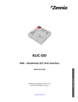
Figure 1. Element scheme
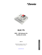
KLIC-DI connects to the KNX bus via the corresponding built-in terminals (1). On the
other hand, this device is connected to the internal PCB board of the A/C unit (P1/P2
connectors), using a 2-wire cable. See Figure 2.
Important: in case of aiming to control the air conditioning both through KLIC-DI and
through the incorporated wired remote control of the actual unit, please refer to the
“Control types” subsection, under section 2.2 in order to ensure that both of them have
been properly configured.
Once the device is provided with power supply from the KNX bus, both the physical
address and the KLIC-DI application programme for commercial A/C systems can be
downloaded.
This device does not need any additional external power as it is entirely powered
through the KNX bus.
The functionality of the main elements is explained below:
Programming Button (3): a short press on this button will set the device into
the programming mode, making the red component of the LED (2) indicator
light up. If the button is held while plugging the device into the KNX bus,
KLIC-DI will go into secure mode, making the red colour of the LED blink
intermittently.
LED Indicator (2): three-colour (red, blue and green) light indicator that
reflects the current state of the device. Apart from showing whether the
1.- KNX Connector
2.- LED Indicator
3.- Programming Button
4.- Input Terminal for the Two-Wire
Communication Cable.

KLIC-DI SKY
http://www.zennio.com Technical Support: http://support.zennio.com
7
device is under the programming or secure modes, this LED will also show
react to the communication between KLIC-DI and the A/C unit, which may be
particularly useful during the installation process. The meaning of the different
colour components is explained next:
➢ Red Component (still): KLIC-DI is under the programming mode.
➢ Red Component (blinking): KLIC-DI is under the secure mode.
➢ Green Component (still): KLIC-DI is not connected to the A/C unit, or the
A/C unit is disconnected from the power supply.
➢ Green Component (blinking): transmission or data flow from the A/C
machine towards KLIC-DI.
➢ Blue Component (blinking): transmission or data flow from KLIC-DI
towards the A/C machine.
Note: each colour component works with independence of the others.
Therefore, for example, if KLIC-DI is set into the programming mode being
the A/C unit disconnected, the perceived colour will be typically a still orange,
as the red and green components are lighting (still).
Input Terminal for the Two-Wire Communication Cable (4): slot for the
connection of the two-wire communication cable that will connect KLIC-DI to
the A/C unit. The other end of the cable, therefore, is intended to be
connected to the P1/P2 ports from the PCB board of the internal unit, or from
the wired remote control of the A/C unit.
Figure 2. Connecting KLIC-DI to the P1/P2 Bus (Master Mode).
A/C System

KLIC-DI SKY
http://www.zennio.com Technical Support: http://support.zennio.com
8
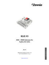
Figure 3. Connecting KLIC-DI to the P1/P2 Bus with a Wired Remote Control (Slave Mode)
Connection Diagram Legend
A
KLIC-DI
B
Wired control
C
A/C unit
P1-P2
Connection base for the A/C unit
1-2
Zennio input terminal
*
The wired remote control needs to work contrary to the
mode (slave/master) set for KLIC-DI (see section 2.2).
For detailed information about the technical features of KLIC DI, as well as on security
and installation procedures, please refer to the device Datasheet, included within the
device packaging and also available at http://www.zennio.com. Reading the KLIC-DI
installation note, available at the same website, is also encouraged.
Note: sections following this point will focus on the KLIC-DI SKY application
programme for commercial A/C machines, and its specific configuration. Please refer to
the KLIC-DI VRV user manual in case of running that particular application programme.
A/C System
Wired control

KLIC-DI SKY
http://www.zennio.com Technical Support: http://support.zennio.com
9
2 CONFIGURATION
2.1 BASIC CONTROL
KLIC-DI allows controlling and monitoring an air-conditioning unit the same way it
would be through the wired remote control provided with it.
Through the KNX bus, the following basic functionalities of the air conditioning unit can
be controlled:
ON/OFF switch of the air-conditioning unit.
Temperature Setpoint between 16 and 32 ºC.
Operation Mode: Auto, Heat, Cool, Fan and Dry.
Fan Speed: configuration of 2 or 3 speed levels.
These functionalities imply changes in the state of the machine, which are periodically
sent to KLIC-DI. When KLIC-DI receives from the machine a state different to the
previous one, it updates the status objects and sends them to the KNX bus.
2.2 ADVANCED FUNCTIONALITY
Apart from basic control functions over the air-conditioning system, KLIC-DI offers
other advanced functionalities that provide added value to the wired remote control:
Scene Configuration: allows establishing a specific parameter combination
to be sent to the machine in order to generate a determined climate ambient.
KLIC-DI allows configuring up to 4 different scenes.
Temporary Switch-Off: allows an automatic and temporary switch-off of the
machine (after a pre-established delay, if set up) when the communication
object associated to this function changes its value. A typical application of
this functionality is linking a window sensor to the automatic switch-off object,
which will make KLIC-DI switch the machine off while the window is open.
Important: check which levels are provided by the A/C unit.

KLIC-DI SKY
http://www.zennio.com Technical Support: http://support.zennio.com
10
Setpoint Restriction: temperature setpoints of commercial air conditioning
systems are typically limited to the range 16-32ºC (please refer to the user
manual of the actual unit). This function of the KLIC-DI device allows
configuring custom setpoint ranges in ETS for the Heat and Cool modes,
provided that the custom values stay within the original range. In case of
receiving a temperature command from the KNX bus with a value exceeding
the configured range, the temperature value sent by KLIC-DI to the machine
will be the corresponding limit value.
Internal Temperature and Reference Temperature: commercial A/C units
include several sensors for measuring the temperature at different internal
points. KLIC-DI monitors the value of one of these internal measures, called
Internal Temperature, which, together with the Reference Temperature, is
used for switching between the Auto-Cool and Auto-Heat modes of the A/C
machine. The Reference Temperature is the actual ambient temperature of
the room under climate control. It is necessary that KLIC-DI provides the
machine with this value, which implies that it should be sent first to KLIC-DI
through the corresponding communication object (generally from an external
sensor).
The A/C unit can control the Auto-Heat and Auto-Cool modes by three
different ways:
1. The machine receives the Reference Temperature and, basing on a
hysteresis value pre-configured by the installer of the machine, it
determines the corresponding auto mode.
2. The machine receives the Internal Temperature and, basing on a
hysteresis value pre-configured by the installer of the machine, it
determines the corresponding auto mode.
3. The machine establishes the auto mode according to the average value
between the Reference Temperature and the Internal Temperature.
The concrete temperature value that triggers the commutation between the
Auto-Cool and Auto-Heat modes depends on the configuration established in
the A/C unit itself. In all of the above cases, this value is compared to the
temperature setpoint so that if the temperature setpoint is higher, the Auto-

KLIC-DI SKY
http://www.zennio.com Technical Support: http://support.zennio.com
11
Heat mode is established; and if the temperature setpoint is lower than this
value, the Auto-Cool mode is established.
Note: it is highly recommended to link the Reference Temperature to a
temperature sensor that periodically monitors the real temperature of the
room, as it may happen that the pre-configuration of the unit is unknown,
causing a wrong behaviour of the Auto mode. The Reference Temperature
communication object has a default value of 25ºC and is only available when
the control type of KLIC-DI is master.
Important: The Daikin indoor units have three different ways to be
programmed in regards with the ambient temperature sensor. This
configuration must be done by a Daikin qualified technician or installer.
1) The indoor unit uses its own return temperature when there is a big
difference between the ambient temperature and the setpoint
temperature. The ambient temperature will be used from the Master
device (remote controller, or KLIC-DI device) when this difference is
small.
2) The indoor unit uses its own return temperature.
3) The indoor unit is only used the ambient temperature from the Master
device (Daikin remote controller, or KLIC-DI device).
Error Management: allows sending messages to the KNX bus informing
about errors. Error management handles both external errors from the A/C
unit itself and those that may arise in the KLIC-DI – A/C unit communication
process.
Apart from reporting external errors, a numerical code associated with them is
also provided and must be consulted in the specific user manual of the
installed air-conditioning system, according to ANNEX II: Correspondence
with A/C Unit Error Codes.
Initial Configuration: allows establishing the desired initial parameters for
the state of the A/C unit after downloading or restarting the device from ETS,
or after recovering from a bus failure. The following may be configured:
ON/OFF state, temperature, mode, fan and swing of the machine. It is also
possible to send the initial values to the KNX bus after the start-up.

KLIC-DI SKY
http://www.zennio.com Technical Support: http://support.zennio.com
12
Control Type: permits defining the control type, master or slave, that KLIC-DI
will work according to (important when KLIC-DI will be used together with
the wired remote control of the A/C unit).
The master control type will correspond to the device directly communicating
with the machine. It will also be in charge of retransmitting the instructions to
the slave control, if any. This configuration will still permit controlling the
machine from the slave control.
This feature allows connecting to the same installation both the KLIC-DI
interface and the wired remote control of the A/C unit, provided that they are
not both configured as masters or as slaves.
Important: in case of having KLIC-DI and the wired remote control operating
together, please, make sure that the control type of both devices is not the
same (necessarily one of them must be master and the other slave).
Notes:
➢ Switching the wired control between the slave and master modes requires
interrupting the power supply in order to make the wired control re-initialise
under the new mode.
➢ If the power supply of the wired control fails, it may be necessary to
disconnect and reconnect the bus voltage of the device after the power
supply has been restored in order for the configuration between the wired
control unit and the KLIC DI to be successful (especially if the KLIC DI has
been configured as master and the wired control as slave).
2.3 TESTING KLIC-DI FROM AN IR REMOTE
KLIC-DI incorporates –next to the LED indicator– an infrared receiver that may be used
together with any of the Zennio IR remotes (such as models ZN1IRZ38 and
ZN1IRZAS) to check the proper control of the A/C machine from KLIC-DI.
Note: KLIC-DI will only respond to infrared orders under the programming mode (i.e.,
with the red component of the LED on).
The action performed by each button of the IR control is shown in Figure 4.


KLIC-DI SKY
http://www.zennio.com Technical Support: http://support.zennio.com
14
3 ETS PARAMETERISATION
To begin with the parameterisation process of the KLIC-DI interface it is necessary,
once the ETS programme has been opened, to import the database of the product
(KLIC-DI SKY application programme).
Next, the device should be added to the project. The configuration process begins by
entering the Parameters tab of the device.
In the following sections a detailed explanation is provided about how to parameterise
the different functionalities of the device in ETS.
3.1 DEFAULT CONFIGURATION
This section shows the default configuration the device configuration starts from.
Figure 5. Default Topology
The default topology window (Figure 5) contains the communication objects associated
to the reception of the control orders for the basic operation of the A/C unit: on/off,
setpoint, mode and fan. In addition, the corresponding status objects (which will report
the updated state values of the A/C system to the KNX bus) are also shown.
When entering the parameter edition for the first time, the following window will be
shown.

KLIC-DI SKY
http://www.zennio.com Technical Support: http://support.zennio.com
15
Figure 6. Default General Configuration
As shown in Figure 6, the configuration window is initially divided into three main tabs:
General: allows individually enabling the control over the advanced
functionalities of the A/C unit.
Mode: allows selecting the communication objects to be used to control the
mode of operation of the A/C unit.
Fan: allows configuring features related to the fan speed of the A/C unit.
The next sections cover all of the above in detail.
3.2 GENERAL
From the General parameter window, it is possible to select the advanced
functionalities of the A/C system (scenes, setpoint restriction, auto OFF, error handling
and initial configuration) to be controlled. All of them, which will be explained in the next
section, are disabled by default.
From the General window it is also possible to configure the desired control type for
KLIC-DI (master control or slave control) and the Internal temperature sending time
(30-255, in seconds), which allows carrying out a periodical sending to the KNX bus of
the internal temperature measured by the machine, even if the value does not change.

KLIC-DI SKY
http://www.zennio.com Technical Support: http://support.zennio.com
16
3.2.1 SCENES
After enabling this function, the left menu will show a new tab named Scenes, from
where it will be possible to set up different scenes (up to 4), consisting each of them in
a set of orders to be sent to the A/C unit upon the reception, through the KNX bus and
by means of the Scenes object, of the corresponding scene value (decreased by 1,
according to the KNX standard).
Figure 7. Scene Configuration
For every enabled scene, the particular parameters that may be configured are the
following:
Scene number. Sets the scene number (1-64) on whose reception (through
the Scenes object, decreased by one) the corresponding configured orders
will be sent to the A/C machine. The available orders are:
➢ On/Off. Brings the possibility of setting the A/C machine state: No change,
on or off.
➢ Temperature. No change, or a New temperature setpoint (from 16ºC to
32ºC).
➢ Mode. No change, Auto, Heat, Dry, Fan or Cool.
➢ Fan. No change, minimum or maximum.
➢ Swing. No change, Swing (in motion) or in any of the five Fixed positions
available.
An example of scene configuration is shown in Figure 8.

KLIC-DI SKY
http://www.zennio.com Technical Support: http://support.zennio.com
17
Figure 8. Scene configuration example (Scene 1)
3.2.2 SETPOINT RESTRICTION
The A/C unit imposes restrictions to the temperature setpoint (typically, only values in
the range 16ºC - 32ºC are available). Nevertheless, KLIC-DI offers the possibility of
establishing new setpoint temperature limits provided that they are still within the A/C
unit predefined limits (please refer to the A/C unit user manual for details).
Setpoint restrictions can be customised independently for the two modes of operation
that require a temperature setpoint: Cool and Heat).
Figure 9. Setting setpoint restriction.
Important: to make KLIC-DI aware of these customised limits, the specific Setpoint
Restriction communication object must be set to “1” (its value is “0” after the device

KLIC-DI SKY
http://www.zennio.com Technical Support: http://support.zennio.com
18
starts up). To control the machine back with the predefined temperature limitations, the
mentioned object needs to be sent the value "0".
Once established the new setpoint restriction for every mode and enabled the
functionality, when an out-of-range value is received from the KNX bus, the A/C
machine will actually be sent a value equal to the corresponding setpoint restriction
(thus, truncating the out-of-range value).
3.2.3 AUTO OFF
This option allows an automatic and temporary switch-off of the A/C machine if a value
change (from value "0" to value "1") in the associated communication object (Auto-
OFF, typically intended to be linked to an open/closed window sensor). If the A/C
machine was already off, the Auto-OFF will still apply, so the machine will remain off
(not being possible to switch it on) until this situation is over.
Figure 10. Auto OFF
The only configurable parameter is:
Delay for Auto-OFF: sets the time, in seconds, KLIC-DI waits before
automatically switching the A/C machine off. Any OFF order received during
the delay will abort the delay and the Auto-OFF will be applied immediately.
Once the Auto-OFF object adopts the value “1”, any ON order will not be sent to the
machine until the object “Auto-OFF” acquires the value “0”. However, any other control
orders (setpoint, fan speed, etc.) received during the open window state will in fact be
taken into account by KLIC-DI and applied afterwards, once the Auto-Off object is back
set to “0” (which will set the machine back to the state it had prior to the Auto-OFF).
Note: switch-on orders sent to the A/C unit from a wired remote control configured as a
master will not be ignored during the open window state (Auto-OFF=1), as KLIC-DI has

KLIC-DI SKY
http://www.zennio.com Technical Support: http://support.zennio.com
19
no authority over the wired remote control. In such case, the Auto-OFF will be aborted
(Auto-OFF=0).
3.2.4 ERROR HANDLING
From this parameter window it is possible to enable the sending of messages to the
KNX bus to report the occurrence of errors, including both internal errors regarding the
communication between KLIC-DI and the A/C unit, and external errors affecting the
A/C unit itself.
Figure 11. Configuring the error handling.
It is possible to select whether to report none, internal, external or both types of error:
Internal errors: when enabled, a new communication object shows up:
"Internal Error: Communication" (1-Bit), which indicates if there is a
problem in the communication between the KLIC-DI and the A/C unit or there
that there is no unit connected. Thus, if its value is "1", there is an error; and if
it is "0", there is no error.
Note: If an internal error communication is active, the next actions are
recommended:
1. If there is a remote wired control in the installation, check whether it
reports any error.
2. Verify that KLIC-DI is properly connected to the A/C unit.
3. Verify that control configuration is correct. Check that the device and
the remote wired control are not both configured as slaves.
4. If internal error is still active, please, contact with Zennio support.

KLIC-DI SKY
http://www.zennio.com Technical Support: http://support.zennio.com
20
External errors: when enabled, two new communication objects show up:
"External Error (Status)" and "Type of external error (Status)". The first
one indicates if an external error is active (value "1") or not (value "0"). The
second object indicates the specific code that identifies the error (please refer
to the specific user manual of the A/C unit and to ANNEX II: Correspondence
with A/C Unit Error Codes).
Important: in case of configuring KLIC-DI as master to operate together with the wired
remote control, error handling functionality must be enabled in order not to cause an
abnormal control or behaviour of the air machine.
3.2.5 TYPE OF CONTROL
The control type of the KLIC-DI interface is also parameterised from the General
window. This can be Master Remote Control or Slave Remote Control, depending
on whether or not there is an additional wired remote control in the bus. Please refer to
the “Control type” subsection under section 2.2.
Figure 12. Configuring the type of control.
3.2.6 SWING
Through this parameter, it is possible to select whether to permit controlling the swing
function (i.e., the slats that address the air flow) of the A/C machine. The availability of
such function in the particular A/C unit being controlled needs to be confirmed in
advance.
/