Page is loading ...

User Guide
RM-702 and RM-802-IM
Two Channel Remote Station
User Guide
Part Number: 399G260 Rev A
Date: May 24, 2018

User Guide| RM-702/RM-802-IM
Document reference
RM-702/RM-802-IM User Guide
399G260 Rev A
Legal disclaimers
Copyright © 2018 HME Clear-Com LtdHME Clear-Com Ltd
All rights reserved
Clear-Com, the Clear-Com logo, and Clear-Com Concert are trademarks or
registered trademarks of HM Electronics, Inc.
The software described in this document is furnished under a license agreement
and may be used only in accordance with the terms of the agreement.
The product described in this document is distributed under licenses restricting its
use, copying, distribution, and decompilation / reverse engineering. No part of this
document may be reproduced in any form by any means without prior written
authorization of Clear-Com, an HME Company.
Clear-Com Offices are located in California, USA; Cambridge, UK; Dubai, UAE;
Montreal, Canada; and Beijing, China. Specific addresses and contact information
can be found on Clear-Com’s corporate website: www.clearcom.com
Clear-Com contacts:
Americas and Asia-Pacific Headquarters
California, United States
Tel: +1 510 337 6600
Email: CustomerServicesUS@clearcom.com
Europe, Middle East, and Africa Headquarters
Cambridge, United Kingdom
Tel: +44 1223 815000
Email: CustomerServicesEMEA@clearcom.com
China Office
Beijing Representative Office
Beijing, P.R. China
Tel: +8610 65811360/65815577
Page 2

User Guide| RM-702/RM-802-IM
Table of contents
1 Compliance 6
2 Operation 9
2.1 Introduction 9
2.2 The Clear-Com Concept 9
2.3 Description 10
2.4 Operation 11
3 Installation 14
3.1 Installation Overview 14
3.2 Description of Front panel Connectors 17
3.3 Headset Connector (Front Panel) 17
3.4 Description of Rear Panel Connectors 18
3.5 Description of Options and Adjustments 19
3.6 Typical System Applications 24
3.7 Actual Applications 26
4 Maintenance 34
4.1 Introduction 34
5 Technical Specifications 35
5.1 RM-702/RM-802-IM Two-Channel Station 35
6 Technical Support and Repair Policy 39
6.1 Technical Support and Repair Policy 39
6.2 Technical Support Policy 39
6.3 Return Material Authorization Policy 41
6.4 Repair Policy 42
Page 3

User Guide| RM-702/RM-802-IM
Important Safety Instructions
1. Read these instructions.
2. Keep these instructions.
3. Heed all warnings.
4. Follow all instructions.
5. Do not use this apparatus near water.
6. Clean only with dry cloth.
7. Do not block any ventilation openings. Install in accordance with the
manufacturer’s instructions.
8. Do not install near any heat sources such as radiators, heat registers, stoves, or
other apparatus (including amplifiers) that produce heat.
9. Only use attachments/accessories specified by the manufacturer.
10. Use only with the cart, stand, tripod, bracket, or table specified by the
manufacturer, or sold with the apparatus. When a cart is used, use caution
when moving the cart/apparatus combination to avoid injury from tip-over.
11. Unplug this apparatus during lightning storms or when unused for long periods
of time.
12. Refer all servicing to qualified service personnel. Servicing is required when the
apparatus has been damaged in any way, such as power-supply cord or plug is
damaged, liquid has been spilled or objects have fallen into the apparatus, the
apparatus has been exposed to rain or moisture, does not operate normally, or
has been dropped.
13. WARNING: To reduce the risk of fire or electric shock, do not expose this
product to rain or moisture.
Page 4

User Guide| RM-702/RM-802-IM
Please familiarize yourself with the safety symbols in Figure 1. When you see these
symbols on this product, they warn you of the potential danger of electric shock if
the station is used improperly. They also refer you to important operating and
maintenance instructions in the manual.
Page 5

User Guide| RM-702/RM-802-IM
1 Compliance
Clear-Com, LLC, an HME Electronics, Inc, company is committed to compliance with
the laws and regulations of each country where Clear-Com markets the product
below.
Applicant Name : Clear-Com, LLC
Applicant Address : 1301 Marina Village Parkway, Suite 105, Alameda, California
94501, United States
Manufacturer Name : HM Electronics, Inc.
Manufacturer Address : 2848 Whiptail Loop, Carlsbad CA 92010 USA
Country of Origin : USA
Brand : Clear-Com
Product Name : Remote Station
Product Regulatory Model Number : RM-702 and RM-802-IM
This document was prepared in the English language. In case this document is
translated into another language and a discrepancy arises between languages, the
English version shall prevail as being the version which best expresses the intent of
the parties. Any notice or communication given in conjunction with this document
must include an English version.
Caution: All products are compliant with regulatory requirements detailed in this
document when the user follows all the installation instructions and operating
conditions per Clear-Com specifications.
Caution: Product modifications not expressly approved by the party responsible
for compliance can void the user’s authority to operate the equipment.
Caution: Use of accessories and peripherals other than those recommended by
Clear-Com may void the product’s compliance as well as the user’s authority to
operate the equipment.
European Union (CE mark)
The CE marking indicates compliance with the following directives and standards.
Directives:
l Electromagnetic Compatibility Directive 2014/30/EU
l Low Voltage Directive 2014/35/EU
l RoHS Directive 2011/65/EU
Standards:
Page 6

User Guide| RM-702/RM-802-IM
l EN 55032, EN 55024, EN 60950-1, EN 50581
Maritime Certification
The regulatory model MS802 bears the DNV-GL mark, indicating conformity with
DNVGL-CG-0339 Edition November 2016.
Location Classes:
The influence of the ambient environment on equipment depends upon the field of
application on board. Environmental testing therefore implies tests being directly
related to intended location on board as well as general tests, which are not directly
related to location. There are five location classes: Temperature, humidity,
vibration, enclosure and EMC. The allowed location of installation on board depends
on the maritime approved location class.
Model RM-802-IM was DNV-GL type approved for Temperature Location Class A,
Humidity Location Class A, Vibration Location Class A, EMC Location Class A & B and
Enclosure Location Class A.
Model RM-802-IM is allowed to be installed in the control room and bridge. For more
details please follow the Table 1 Location Class below.
Model RM-802-IM is not allowed to be installed in machinery spaces, pump room,
holds, rooms with no heating and open deck.
Encore Models with DNV Certification, for use in Industrial and Marine Applications
RM-802-IM
Temperature 0°C to +50°C
Humidity Relative humidity up to 96 %
Vibration
Frequency range: 2 –13.2 Hz,
Amplitude: 1.0 mm (peak value)
Frequency range: 13.2–100 Hz,
Acceleration amplitude: 0.7 g
EMC DNVGL-CG-0339 - Class A & B
Enclosure IP20
Page 7

User Guide| RM-702/RM-802-IM
Waste Electrical and Electronic Equipment (WEEE)
The European Union (EU) WEEE Directive (2012/19/EU) places an obligation on
producers (manufacturers, distributors and/or retailers) to take-back electronic
products at the end of their useful life. The WEEE Directive covers most Clear-Com
products being sold into the EU as of August 13, 2005. Manufacturers, distributors
and retailers are obliged to finance the costs of recovery from municipal collection
points, reuse, and recycling of specified percentages per the WEEE requirements.
Instructions for Disposal of WEEE by Users in the European Union
The symbol shown below is on the product or on its packaging which indicates that
this product was put on the market after August 13, 2005 and must not be disposed
of with other waste. Instead, it is the user’s responsibility to dispose of the user’s
waste equipment by handing it over to a designated collection point for the
recycling of WEEE. The separate collection and recycling of waste equipment at the
time of disposal will help to conserve natural resources and ensure that it is
recycled in a manner that protects human health and the environment. For more
information about where you can drop off your waste equipment for recycling,
please contact your local authority, your household waste disposal service or the
seller from whom you purchased the product.
Page 8

User Guide| RM-702/RM-802-IM
2 Operation
2.1 Introduction
Congratulations on choosing this Clear-Com product. Clear-Com was established in
1968 and remains the market leader in providing intercoms for entertainment,
educational, broadcast, and industrial applications. The ruggedness and high build-
quality of Clear-Com products defines the industry standard. In fact, many of our
original beltpacks and main stations are still in daily use around the world.
2.2 The Clear-Com Concept
Clear-Com is a closed-circuit intercom system that consistently provides high-
clarity communication in high-noise and low-noise environments. A basic system
consists of a single- or multi-channel power supply or main station connected to
various single- or multi-channel remote stations, such as beltpacks and
loudspeaker stations.
Clear-Com manufactures a wide variety of both portable and fixed-installation
units. All are compatible with each other. Clear-Com intercom systems can also
interface with other communication systems and devices.
Clear-Com stations are interconnected with two-conductor, shielded microphone
cable, using 3-pin XLR connectors. One wire carries the DC power from a main
station or power supply to all remote stations, and the other wire carries two-way
(duplex) audio information. The shield acts as a common ground. One termination
(per channel) is needed throughout the intercom network, and is usually located in
the main station or power supply.
Clear-Com is a distributed amplifier system; each main and remote station houses
its own mic preamplifier, headset or speaker power amplifier, and signaling
circuitry. Low-impedance mic input lines and specially designed circuitry make
Clear-Com channels virtually immune to RFI and dimmer noise.
Clear-Com main stations, power supplies and certain remote stations have
auxiliary program inputs with local volume control, allowing an external audio
source to be fed to the intercom system.
Visual signal circuitry (call lights), a standard feature on most main and remote
stations, allows the user to attract the attention of operators who have removed
their headsets.
Depending on the type of main and remote stations selected (and assuming that
enough DC power is available) remote stations can be distributed along a mile of
Page 9

User Guide| RM-702/RM-802-IM
wire. Remote stations bridge the intercom line at a very high impedance and place
a minimum load on the line. The audio level always remains constant, and does not
fluctuate as stations leave and join the network.
2.3 Description
The RM-702/RM-802-IM is one of a series of professional intercom stations
specifically designed for the broadcast industry. This two-channel, one-rack-space
station is ideal for ENG and EFP trucks, production studio consoles, and small TV
facilities. The station can be tailored to your needs through its programmable talk
button options. The RM-702/RM-802-IM is compatible with all Clear-Com party-line
intercoms.
The station also incorporates an internal single-channel program interrupt system
(IFB). When activated, one or more stations can interrupt the program to a talent
with Clear-Com’s wired or wireless talent receivers. Direct connection to Clear-
Com’s IFB system is easily accomplished through a 1/4 in. (0.62 cm) phone jack on
the rear panel intended to directly connect to a Clear-Com MA-704.
The RM-702/RM-802-IM remote speaker/headset station allows selectable two-
channel talking and/or listening on a Clear-Com intercom system. The operator can
communicate on either of the channels separately or on both at once. Illuminated
dual-action talk buttons provide electronic momentary or latching capability. The
latching feature may be disabled if desired. The talk buttons can also be remote
controlled for footswitch or other use. Monitoring activity is possible through the
speaker or headset or both at once.
The RM-702/RM-802-IM features visual call signaling to attract the attention of
operators who have removed their headsets or turned off their speakers.
This station accepts dynamic headsets. The station accepts two different lengths of
plug-in gooseneck microphones, 9 in. (22.86 cm) and 18 in. (45.72 cm), to allow for
different operating locations/positions.
The station’s speaker can be turned on or off by a convenient front panel switch
when private conversation via the headset is desired. A speaker dipping circuit
provides an additional amount of acoustic output before feedback. This feature
helps to reduce feedback when stations are placed in close proximity to each other.
The station accepts a balanced program input for monitoring external audio in the
headset or speaker. Individual sidetone controls for each channel allow the
operator to vary the level of his/her own voice as heard in the headset/speaker.
Studio announce allows control of a paging speaker in a studio. A front panel button
activates this function and an associated relay.
Page 10

User Guide| RM-702/RM-802-IM
The RM-702/RM-802-IM installs in a standard 19 in. (48.26 cm) equipment rack,
using only one rack space. The station provides two 3-pin, XLR connectors for input
and loop-through on each channel.
2.4 Operation
Normal operation of the RM-702/RM-802-IM requires access only to the front panel
controls. For intercom operation, set the listen level controls for each channel to the
desired level and press the talk switches when talking. If a headset is being used,
set the sidetone control for the receiving channel for the desired amount of
sidetone in the earphone. If the panel mic and speaker are being used, set the
sidetone control for minimum feed-through to the speaker to prevent feedback.
Panel Mic
Speaker
Program
Level
On
Off
Sidetone
Null
Level
Announce
Level
ProgramProgram
Channel A Channel B
Sidetone
Null
Volume
Volume
Talk
Headset
Panel Mic
Headset
2-Channel
Remote Station
RM-702
Call
Talk
Buttons
Call
Buttons
Channel A
Volume
Channel B
Volume
Channel A
Sidetone
Channel B
Sidetone
Program
Level A
Program
Level B
Speaker
Switch
MIC
Select
Switch
Announce
Button
Program
Monitor
Level
Panel
Microphone
Panel
Headset
The rest of this section is a detailed description of each control.
2.4.1 Talk Buttons
Each channel has its own illuminated talk button for activating the microphone feed
to a given channel. Mechanically, the pushbutton is momentary in action; however,
electrically the button has dual action (momentary or latching) depending on how
the button is pressed. The latching function can be defeated with a rear-panel DIP
switch.
l LATCHING: Pressing the button quickly will toggle the talk function,
alternately turning it on or off.
l MOMENTARY: Pressing the button for longer than 1/4 second will turn the
button press into a momentary function such that when the button is released
Page 11

User Guide| RM-702/RM-802-IM
the talk function will turn off. In any case the talk function is activated all of
the time the button is pressed.
l TALK INDICATION: The talk button illuminates yellow when a talk is
activated and blue when talk is not active.
l CALL INDICATION: The call button will flash red when a call signal is
received on that channel.
l AUTO-CALL ON TALK: Each channel can be set to send a call signal when the
talk function is active. This function is used to activate IFB circuits or any
other call-activated function available on other stations. A DIP switch on the
rear panel activates this function.
l SPEAKER DIP FUNCTION: Pressing either talk button will reduce the output
level of the speaker by a set amount to avoid feedback.
2.4.2 Call Buttons
Each channel has its own call button. Pressing the call button at any time will send a
call signal on that channel regardless of the activation of the talk circuit for that
channel.
The call button for that channel will flash red while the call button is pressed
indicating the presence of a call signal on the line.
2.4.3 Volume Controls
Each channel has a separate volume control for monitoring incoming audio.
Listening is always on and is not controlled by any logic. To listen to a channel, turn
up the appropriate control. To not listen to a channel, turn the control completely
off.
2.4.4 SideTone Controls
Each channel has a sidetone null control. This control sets the amount of the
microphone that is heard in the earphone from that channel.
This control is a true hybrid null control and therefore is sensitive to changes in line
loading. For headphone use, it is best to find the null for a given channel and then
rotate the control clockwise to obtain the desired sidetone level.
If the speaker and panel microphone are used together, providing a possible
acoustic feedback path, it will be necessary to use an almost complete null of the
sidetone control.
Page 12

User Guide| RM-702/RM-802-IM
2.4.5 Program Send Level Control for Channel A and B
Both channels A and B have a program send level control that sets the volume of
program audio being sent to that channel when the program is activated.
2.4.6 Speaker On/Off Switch
The switch marked speaker on/off is used to turn the speaker on and off.
2.4.7 Mic Select Switch
The mic select switch enables the operator to select which microphone is active.
2.4.8 Program Monitor Level Control
The program volume control sets the amount of the program signal heard directly in
the headphone or speaker. This control only affects what is heard in the headphone
or speaker and does not affect program feed to the intercom lines.
2.4.9 Announce Button
The announce button allows the operator to instantly use the microphone input to
directly talk to a system external to the intercom such as a paging
speaker/amplifier in another room. A dry set of relay contacts on the rear panel is
also available for activating external switching, as needed when the announce
button is pressed.
The button illuminates amber when pressed. Pressing the announce button
momentarily disables any active talks. Active talk circuits will be restored when the
button is released.
The talk-muting action can be defeated if desired by moving an internal jumper.
(See the section on internal options and adjustments.)
Page 13

User Guide| RM-702/RM-802-IM
3 Installation
This section discusses the installation of the RM-702/RM-802-IM in an intercom
system including typical applications, overall installation theory, detail of each
connector, and adjustments.
3.1 Installation Overview
This section describes the Clear-Com concept of intercom line connection. The
following subjects are discussed:
l Intercom line connection
l Line termination
l Station powering
l Cable considerations
3.1.1 Intercom Line Connection
The RM-702/RM-802-IM provides male and female XLR-3 connectors for each
intercom line, which are looped through.
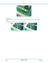
3.1.2 Connecting or Isolating RM-702/RM-802-IM Channels
An internal jumper in the RM-702/RM-802-IM unit allows you to defeat the power-
channel isolation of the unit, as described in the following procedure.
Note: This adjustment should only be carried out by qualified service personnel.
Page 14

User Guide| RM-702/RM-802-IM
JP4
JP2
JP3
JP6
JP5
1. Please observe anti-static procedures. The circuit cards can be damaged by
static electricity. Please ground yourself and tools before touching any circuit
cards.
2. Remove the cover of the RM-702/RM-802-IM.
3. On the main circuit board, locate the JP4 three-pin jumper.
The jumper is located on the rightmost upper portion of the circuit card, when
viewed from the front of the unit. The label “J4” appears behind the jumper. A
jumper plug is placed over pins 2 and 3.
4. Do one of the following:
a. To connect the two channels, place the jumper plug over pins 1 and 2.
JP4 1
2
3
b. To isolate the two channels, place the jumper plug over pins 2 and 3.
JP4
1
2
3
Page 15

User Guide| RM-702/RM-802-IM
The RM-702 unit is shipped with the jumper plug over pins 2 and 3 to maintain
the power-channel isolation. Power-channel isolation ensures that if one
channel loses power, the other channel will continue to operate.
5. Replace the cover of the RM-702/RM-802-IM.
3.1.3 Line Termination
The fundamental concept of Clear-Com party-line intercom is that all stations
provide high-impedance current-sourced signals into a single common system
termination.
The receive or listen section of stations contain a hybrid null circuit that attempts to
reject (null) any talk signal being sent by that station on that channel. The hybrid
null circuit depends on a known impedance on the intercom line to accomplish this.
Variations in impedance on the line upset the null.
All Clear-Com Intercom lines must be terminated. Care must be taken not to fail to
terminate or to “double”-terminate a line. All unused intercom inputs must be
terminated to keep the line drive circuits stable.
The RM-702/RM-802-IM does not provide termination on the intercom line. Clear-
Com main stations and power supplies provide switch-selectable termination
networks on all intercom output lines. It is up to the user to determine where the
termination will be provided. An unterminated line will cause excessive levels,
possible oscillation of line drivers, and severe unbalance of hybrid null networks. A
double- or multiple-terminated line will cause low levels and severe unbalance of
hybrid null circuits.
The termination of an intercom line (or channel) is a 220 Ohm resistor in series with
a 4.7 KOhm that is paralleled with a 10 uF capacitor.
3.1.4 Station Powering
Typical Clear-Com systems are powered by a main station or a power supply.
Clear-Com power supplies can be paralleled to increase the number of remote
stations that can be operated in a system.
3.1.5 Cable Considerations
The Clear-Com intercom line is intended to run on a shielded twisted pair of cable
per channel of intercom. One conductor carries full duplex (“two-way”) audio, the
other conductor carries the DC power for remote stations. The shield is used for
ground return for audio and power. When choosing interconnect cable, keep the
following considerations in mind:
Page 16

User Guide| RM-702/RM-802-IM
l DC resistance of the ground or common conductor affects crosstalk. For runs
longer than 500 ft. (152.5 m), do not use wire smaller than 20 gauge.
l The capacitance of the interconnect cable affects system frequency response
and sidetone stability. Total capacitance should not be greater than 0.25 uF.
Portable Installation Cable: Practical cable for portable system interconnections
is flexible, two-conductor, shielded microphone cable. For runs less than 500 ft.
(152.5 m), a cable made of 24-gauge wire is acceptable. For runs longer than
500ft. (152.5 m), use a 20-gauge cable or larger.
Permanent installation Cable: Vinyl-jacketed shielded pair is the cable of choice
for permanent installations. Use a low-capacitance 20-gauge wire for short runs of
less than 500 ft. (152.5 m) and 18-gauge cable for runs greater than 500 ft. (152.5
m). Placing the cable in conduit is recommended, but not necessary.
Multi-pair cable that is individually shielded is acceptable for use in multi-channel
systems. For cross-talk considerations, the shields must be tied together on both
ends of the cable to produce the lowest possible DC path for ground return.
3.2 Description of Front panel Connectors
3.3 Headset Connector (Front Panel)
Note: The following is a description of a recommended headset.
Mic Type --- Dynamic, for details see the technical specifications
Wiring
Pin 1 --- Mic common
Pin 2 --- Mic hot
Pin 3 --- Headphone common
Pin 4 --- Headphone hot
3.3.1 Panel Mic Connector (Front Panel)
Clear-Com provides two plug-in panel microphones for use on the RM-702/RM-802-
IM. The GM-9 is 9 in. (22.86 cm) long and GM-18 is 18 in. (45.72 cm) long. The
microphone is of the electret type. The microphone has a built-in 1/4 in. (0.64cm)
phone jack for a connector. A mating receptacle is mounted on the RM-702/RM-
802-IM.
To install a GM-9 or GM-18 panel mount microphone, use the following steps:
Page 17

User Guide| RM-702/RM-802-IM
1. Check the set screw in the mic-mounting flange to make sure it is clear of the
threads in the bushing.
2. Screw the microphone into the bushing hand-tight.
3. Set the set screw on top of the bushing to lock the mic in place.
3.4 Description of Rear Panel Connectors
Intercom Channel A Intercom Channel BRM-702
Hot Mic/
C-C IFB
System
Call
On T
alk
A
Call
On T
alk
B
Intrp
t An
nc
Intrp
t E
xt IF
B
Long
Line
A
Long Line B
Prog
Int
A
Prog
Int B
On
Off
Mom T
alk
B
Mom T
alk
A
Prog
Feed B
Prog
Feed
A
Accessory
Intercom
Channel
A
Intercom
Channel
B
Accessory
Port
Hot Mic/
C-C IFB
System
DIP
Switches
3.4.1 Intercom Line Connectors
(Rear Panel, XLR-3 2 Male & 2 Female)
The RM-702/RM-802-IM has a male and female pair of XLR-3 connectors for each
intercom line. The male-female pair of connectors are wired parallel and intended
for loop-through connection.
The pinout of the intercom connectors is as follows:
Pin 1 --- Ground (shield)
Pin 2 --- Power
Pin 3 --- Audio
3.4.2 IFB/Hot Mic (Rear Panel, 1/4-Inch Phone Jack)
A 1/4in. (0.64cm) phone jack marked IFB/HOT mic provides an output signal from
the selected microphone. This output is intended to work with Clear-Com’s MA-704
IFB control panel. A control signal into this connector from the MA-704 causes all
active talks from the station to cease and only sends the IFB output.
The pin description of the connector is as follows:
Page 18

User Guide| RM-702/RM-802-IM
Tip --- Microphone audio output
Ring --- Control signal (>15 VDC)
Sleeve --- Ground (shield)
3.4.3 Accessory (Rear Panel, DB-15F)
The accessory DB-15F connector on the rear panel provides program input,
announce audio output, announce relay contacts, and foot switch inputs for
activating a talk on either channel. The pin assignment of the connector is as
follows:
1
2
3
4
5
6
7
8
9
10
11
12
13
14
15
“ACCESSORY” CONNECTOR
DB-15F
Foot Switch Common
Foot Switch “B”
Foot Switch “A”
GND
Announce Relay N.C. Contact
Announce Relay Wiper
Announce Relay N.O. Contact
GND
GND
– Announce Audio Output
+ Announce Audio Output
Power (+30 VDC)
GND
– Program Input
+ Program Input
3.5 Description of Options and Adjustments
3.5.1 DIP Switch Option Switches (Rear Panel)
Twelve DIP switches on the rear panel enable various options in the station:
l PROGAM ENABLE A: Enables program audio on channel A when set to the on
position.
l PROGRAM ENABLE B: Enables program audio channel B when set to the on
position.
l MOM TALK A: Setting the momentary talk A switch to the on position will
disable the latching function of the channel A talk button. In this mode, the
Page 19

User Guide| RM-702/RM-802-IM
talk button must always be held in continuously while the operator is talking
on channel A.
l MOM TALK B: Setting the momentary talk B switch to the on position will
disable the latching function of the channel B talk button. In this mode, the
talk button must always be held in continuously while the operator is talking
on channel B.
l CALL ON TALK A: If the call on talk A switch is set to the on position, a call
signal will be placed on channel A whenever the talk function is activated. This
can be used to activate any call-activated functions available on other
stations.
l CALL ON TALK B: If the call on talk B switch is set to the on position, a call
signal will be placed on channel B whenever the talk function is activated. This
can be used to activate any call-activated functions available on other
stations.
l INTRPT ANNC: If the interrupt announce switch is set to the on position,
pressing the announce button will disconnect the microphone from the
intercom line(s). This will allow announcements to be made without being
heard over the intercom channels.
l INTRPT EXT IFB: When the hot mic output is connected to Clear-Com’s IFB
system and the interrupt external IFB switch is set to the on position, pressing
a key on the IFB system will disconnect the selected headset or panel
microphone from the intercom line(s). This allows the RM-702/RM-802-IM
microphone to be used to cue talent without affecting intercom line
communication.
l LONG LINE A: If a long cable run on channel A is unavoidable and approaches
1,000 ft. (305 m) or more, set the long line A option switch to the on position.
The ability to set a sidetone null on channel A depends upon properly setting
this switch.
l LONG LINE B: If a long cable run on channel B is unavoidable and approaches
1,000 ft. (305 m) or more, set the long line B option switch to the on position.
The ability to set a sidetone null on channel B depends upon properly setting
this switch.
l PROGRAM INTERRUPT A: Interrupts the program audio to channel A while a
call signal is sent on channel A (default).
You can change this option so that a talk signal, rather than call signal,
interrupts the program audio on channel A. You do this by re-setting an
Page 20
/