
KVM Switch
CS1708A / CS1716A
User Manual
www.aten.com

CS1708
A
/ CS1716
A
User Manual
ii
EMC Information
FEDERAL COMMUNICATIONS COMMISSION INTERFERENCE
STATEMENT: This equipment has been tested and found to comply with the
limits for a Class A digital device, pursuant to Part 15 of the FCC Rules. These
limits are designed to provide reasonable protection against harmful
interference when the equipment is operated in a commercial environment.
This equipment generates, uses, and can radiate radio frequency energy and, if
not installed and used in accordance with the instruction manual, may cause
harmful interference to radio communications. Operation of this equipment in
a residential area is likely to cause harmful interference in which case the user
will be required to correct the interference at his own expense.
The device complies with Part 15 of the FCC Rules. Operation is subject to the
following two conditions: (1) this device may not cause harmful interference,
and (2) this device must accept any interference received, including
interference that may cause undesired operation.
FCC Caution: Any changes or modifications not expressly approved by the
party responsible for compliance could void the user's authority to operate this
equipment.
Warning: Operation of this equipment in a residential environment could
cause radio interference.
Achtung: Der Gebrauch dieses Geräts in Wohnumgebung kann
Funkstörungen verursachen.
KCC Statement
RoHS
This product is RoHS compliant.

CS1708
A
/ CS1716
A
User Manual
iii
User Information
Online Registration
Be sure to register your product at our online support center:
Telephone Support
For telephone support, call this number:
User Notice
All information, documentation, and specifications contained in this manual
are subject to change without prior notification by the manufacturer. The
manufacturer makes no representations or warranties, either expressed or
implied, with respect to the contents hereof and specifically disclaims any
warranties as to merchantability or fitness for any particular purpose. Any of
the manufacturer's software described in this manual is sold or licensed as is.
Should the programs prove defective following their purchase, the buyer (and
not the manufacturer, its distributor, or its dealer), assumes the entire cost of all
necessary servicing, repair and any incidental or consequential damages
resulting from any defect in the software.
The manufacturer of this system is not responsible for any radio and/or TV
interference caused by unauthorized modifications to this device. It is the
responsibility of the user to correct such interference.
The manufacturer is not responsible for any damage incurred in the operation
of this system if the correct operational voltage setting was not selected prior
to operation. PLEASE VERIFY THAT THE VOLTAGE SETTING IS
CORRECT BEFORE USE.
International http://eservice.aten.com
International 886-2-8692-6959
China 86-400-810-0-810
Japan 81-3-5615-5811
Korea 82-2-467-6789
North America 1-888-999-ATEN ext 4988
1-949-428-1111

CS1708
A
/ CS1716
A
User Manual
iv
Package Contents
The CS1708
A
/ CS1716
A
package consists of:
1 CS1708
A
/ CS1716
A
KVM Switch with Standard Rack Mounting Kit
2 Custom KVM Cable Sets
1 Console Cable
1 Firmware Upgrade Cable
1 Foot Pad Set (4 pcs)
1 Power Adapter
1 User Instructions*
Check to make sure that all the components are present and that nothing got
damaged in shipping. If you encounter a problem, contact your dealer.
Read this manual thoroughly and follow the installation and operation
procedures carefully to prevent any damage to the unit, and/or any of the
devices connected to it.
* Features may have been added to the CS1708
A
/ CS1716
A
since this manual
was published. Please visit our website to download the most up-to-date
version of the manual.
© Copyright 2008–2020 ATEN® International Co., Ltd.
Manual Part No. PAPE-0293-100G
Manual Date: 2020-07-23
ATEN and the ATEN logo are registered trademarks of ATEN International Co., Ltd. All rights reserved.
All other brand names and trademarks are the registered property of their respective owners.

CS1708
A
/ CS1716
A
User Manual
v
Contents
EMC Information . . . . . . . . . . . . . . . . . . . . . . . . . . . . . . . . . . . . . . . . . . . . . ii
RoHS. . . . . . . . . . . . . . . . . . . . . . . . . . . . . . . . . . . . . . . . . . . . . . . . . . . . . . ii
User Information . . . . . . . . . . . . . . . . . . . . . . . . . . . . . . . . . . . . . . . . . . . . .iii
Online Registration . . . . . . . . . . . . . . . . . . . . . . . . . . . . . . . . . . . . . . . .iii
Telephone Support . . . . . . . . . . . . . . . . . . . . . . . . . . . . . . . . . . . . . . . .iii
User Notice . . . . . . . . . . . . . . . . . . . . . . . . . . . . . . . . . . . . . . . . . . . . . .iii
Package Contents. . . . . . . . . . . . . . . . . . . . . . . . . . . . . . . . . . . . . . . . . . . iv
Contents . . . . . . . . . . . . . . . . . . . . . . . . . . . . . . . . . . . . . . . . . . . . . . . . . . . v
About this Manual . . . . . . . . . . . . . . . . . . . . . . . . . . . . . . . . . . . . . . . . . . .viii
Conventions . . . . . . . . . . . . . . . . . . . . . . . . . . . . . . . . . . . . . . . . . . . . . . . ix
Product Information. . . . . . . . . . . . . . . . . . . . . . . . . . . . . . . . . . . . . . . . . . ix
Chapter 1.
Introduction
Overview . . . . . . . . . . . . . . . . . . . . . . . . . . . . . . . . . . . . . . . . . . . . . . . . . . . 1
Features . . . . . . . . . . . . . . . . . . . . . . . . . . . . . . . . . . . . . . . . . . . . . . . . . . . 2
Requirements . . . . . . . . . . . . . . . . . . . . . . . . . . . . . . . . . . . . . . . . . . . . . . . 3
Console . . . . . . . . . . . . . . . . . . . . . . . . . . . . . . . . . . . . . . . . . . . . . . . . . 3
Computers. . . . . . . . . . . . . . . . . . . . . . . . . . . . . . . . . . . . . . . . . . . . . . . 3
Cables . . . . . . . . . . . . . . . . . . . . . . . . . . . . . . . . . . . . . . . . . . . . . . . . . . 3
Operating Systems . . . . . . . . . . . . . . . . . . . . . . . . . . . . . . . . . . . . . . . .4
Components . . . . . . . . . . . . . . . . . . . . . . . . . . . . . . . . . . . . . . . . . . . . . . . .4
Front View . . . . . . . . . . . . . . . . . . . . . . . . . . . . . . . . . . . . . . . . . . . . . . .4
Rear View . . . . . . . . . . . . . . . . . . . . . . . . . . . . . . . . . . . . . . . . . . . . . . . 6
Chapter 2.
Hardware Setup
Overview . . . . . . . . . . . . . . . . . . . . . . . . . . . . . . . . . . . . . . . . . . . . . . . . . . . 7
Before You Begin . . . . . . . . . . . . . . . . . . . . . . . . . . . . . . . . . . . . . . . . . . . . 7
Stacking and Rack Mounting . . . . . . . . . . . . . . . . . . . . . . . . . . . . . . . . . . .8
Stacking. . . . . . . . . . . . . . . . . . . . . . . . . . . . . . . . . . . . . . . . . . . . . . . . .8
Rack Mounting – Front . . . . . . . . . . . . . . . . . . . . . . . . . . . . . . . . . . . . .9
Rack Mounting – Rear. . . . . . . . . . . . . . . . . . . . . . . . . . . . . . . . . . . . . 11
Grounding . . . . . . . . . . . . . . . . . . . . . . . . . . . . . . . . . . . . . . . . . . . . . . . . . 13
Single Level Installation . . . . . . . . . . . . . . . . . . . . . . . . . . . . . . . . . . . . . . 14
Cable Connection Diagrams . . . . . . . . . . . . . . . . . . . . . . . . . . . . . . . . . . . 16
Daisy Chain Installations. . . . . . . . . . . . . . . . . . . . . . . . . . . . . . . . . . . . . . 17
Chapter 3.
Basic Operation
Hot Plugging . . . . . . . . . . . . . . . . . . . . . . . . . . . . . . . . . . . . . . . . . . . . . . .21
Changing Station Positions . . . . . . . . . . . . . . . . . . . . . . . . . . . . . . . . . 21
Hot Plugging KVM Ports . . . . . . . . . . . . . . . . . . . . . . . . . . . . . . . . . . . 21
Hot Plugging Console Ports . . . . . . . . . . . . . . . . . . . . . . . . . . . . . . . . 21
Port Selection . . . . . . . . . . . . . . . . . . . . . . . . . . . . . . . . . . . . . . . . . . . . . . 22

CS1708
A
/ CS1716
A
User Manual
vi
Manual Port Switching . . . . . . . . . . . . . . . . . . . . . . . . . . . . . . . . . . . . 22
Port ID Numbering . . . . . . . . . . . . . . . . . . . . . . . . . . . . . . . . . . . . . . . . . . 22
Powering Off and Restarting. . . . . . . . . . . . . . . . . . . . . . . . . . . . . . . . . . . 23
USB Peripheral Devices . . . . . . . . . . . . . . . . . . . . . . . . . . . . . . . . . . . . . . 23
Chapter 4.
OSD Operation
OSD Overview . . . . . . . . . . . . . . . . . . . . . . . . . . . . . . . . . . . . . . . . . . . . . 25
Manufacturing Number . . . . . . . . . . . . . . . . . . . . . . . . . . . . . . . . . . . . 25
OSD Login. . . . . . . . . . . . . . . . . . . . . . . . . . . . . . . . . . . . . . . . . . . . . . 25
OSD Hotkey . . . . . . . . . . . . . . . . . . . . . . . . . . . . . . . . . . . . . . . . . . . . 25
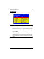
OSD Main Screen . . . . . . . . . . . . . . . . . . . . . . . . . . . . . . . . . . . . . . . . 26
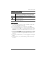
OSD Main Screen Headings. . . . . . . . . . . . . . . . . . . . . . . . . . . . . . . . 27
OSD Navigation . . . . . . . . . . . . . . . . . . . . . . . . . . . . . . . . . . . . . . . . . 27
OSD Functions . . . . . . . . . . . . . . . . . . . . . . . . . . . . . . . . . . . . . . . . . . . . . 28
F1: GOTO . . . . . . . . . . . . . . . . . . . . . . . . . . . . . . . . . . . . . . . . . . . . . . 28
F2: LIST . . . . . . . . . . . . . . . . . . . . . . . . . . . . . . . . . . . . . . . . . . . . . . . 29
F3: SET. . . . . . . . . . . . . . . . . . . . . . . . . . . . . . . . . . . . . . . . . . . . . . . . 30
F4: ADM . . . . . . . . . . . . . . . . . . . . . . . . . . . . . . . . . . . . . . . . . . . . . . . 32
F5: SKP. . . . . . . . . . . . . . . . . . . . . . . . . . . . . . . . . . . . . . . . . . . . . . . . 35
F6: BRC . . . . . . . . . . . . . . . . . . . . . . . . . . . . . . . . . . . . . . . . . . . . . . . 36
F7: SCAN . . . . . . . . . . . . . . . . . . . . . . . . . . . . . . . . . . . . . . . . . . . . . . 37
F8: LOUT . . . . . . . . . . . . . . . . . . . . . . . . . . . . . . . . . . . . . . . . . . . . . . 38
Chapter 5.
Keyboard Port Operation
Hotkey Port Control . . . . . . . . . . . . . . . . . . . . . . . . . . . . . . . . . . . . . . . . . 39
Invoke Hotkey Mode . . . . . . . . . . . . . . . . . . . . . . . . . . . . . . . . . . . . . . . . . 40
Select the Active Port . . . . . . . . . . . . . . . . . . . . . . . . . . . . . . . . . . . . . . . . 41
Auto Scan Mode . . . . . . . . . . . . . . . . . . . . . . . . . . . . . . . . . . . . . . . . . . . . 42
Invoking Auto Scan: . . . . . . . . . . . . . . . . . . . . . . . . . . . . . . . . . . . . . . 42
Skip Mode. . . . . . . . . . . . . . . . . . . . . . . . . . . . . . . . . . . . . . . . . . . . . . . . . 43
Computer Keyboard / Mouse Reset . . . . . . . . . . . . . . . . . . . . . . . . . . . . . 44
Hotkey Beeper Control . . . . . . . . . . . . . . . . . . . . . . . . . . . . . . . . . . . . . . . 44
Quick Hotkey Control . . . . . . . . . . . . . . . . . . . . . . . . . . . . . . . . . . . . . . . . 45
OSD Hotkey Control . . . . . . . . . . . . . . . . . . . . . . . . . . . . . . . . . . . . . . . . . 45
Port OS Control . . . . . . . . . . . . . . . . . . . . . . . . . . . . . . . . . . . . . . . . . . . . 46
Set USB Speed. . . . . . . . . . . . . . . . . . . . . . . . . . . . . . . . . . . . . . . . . . . . . 46
Restore Default Values. . . . . . . . . . . . . . . . . . . . . . . . . . . . . . . . . . . . . . . 47
Hotkey Summary Table . . . . . . . . . . . . . . . . . . . . . . . . . . . . . . . . . . . . . . 48
Chapter 6.
Keyboard Emulation
Mac Keyboard. . . . . . . . . . . . . . . . . . . . . . . . . . . . . . . . . . . . . . . . . . . . . . 49
Sun Keyboard . . . . . . . . . . . . . . . . . . . . . . . . . . . . . . . . . . . . . . . . . . . . . . 50
Chapter 7.

CS1708
A
/ CS1716
A
User Manual
vii
The Firmware Upgrade Utility
Introduction . . . . . . . . . . . . . . . . . . . . . . . . . . . . . . . . . . . . . . . . . . . . . . . . 51
Downloading the Firmware Upgrade Package . . . . . . . . . . . . . . . . . . 51
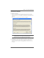
Preparation . . . . . . . . . . . . . . . . . . . . . . . . . . . . . . . . . . . . . . . . . . . . . . . . 52
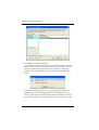
Starting the Upgrade. . . . . . . . . . . . . . . . . . . . . . . . . . . . . . . . . . . . . . . . . 53
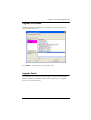
Upgrade Succeeded . . . . . . . . . . . . . . . . . . . . . . . . . . . . . . . . . . . . . . . . . 55
Upgrade Failed . . . . . . . . . . . . . . . . . . . . . . . . . . . . . . . . . . . . . . . . . . . . .55
Firmware Upgrade Recovery . . . . . . . . . . . . . . . . . . . . . . . . . . . . . . . . . . 56
Appendix
Safety Instructions. . . . . . . . . . . . . . . . . . . . . . . . . . . . . . . . . . . . . . . . . . . 57
General . . . . . . . . . . . . . . . . . . . . . . . . . . . . . . . . . . . . . . . . . . . . . . . . 57
Rack Mounting . . . . . . . . . . . . . . . . . . . . . . . . . . . . . . . . . . . . . . . . . . 59
Technical Support . . . . . . . . . . . . . . . . . . . . . . . . . . . . . . . . . . . . . . . . . . .60
International. . . . . . . . . . . . . . . . . . . . . . . . . . . . . . . . . . . . . . . . . . . . . 60
North America . . . . . . . . . . . . . . . . . . . . . . . . . . . . . . . . . . . . . . . . . . .60
Specifications . . . . . . . . . . . . . . . . . . . . . . . . . . . . . . . . . . . . . . . . . . . . . . 61
Connection Tables . . . . . . . . . . . . . . . . . . . . . . . . . . . . . . . . . . . . . . . . . . 62
CS1708A . . . . . . . . . . . . . . . . . . . . . . . . . . . . . . . . . . . . . . . . . . . . . . . 62
CS1716A . . . . . . . . . . . . . . . . . . . . . . . . . . . . . . . . . . . . . . . . . . . . . . . 62
Supported KVM Switches . . . . . . . . . . . . . . . . . . . . . . . . . . . . . . . . . . . . . 63
Restoring Factory Default Settings . . . . . . . . . . . . . . . . . . . . . . . . . . . . . . 64
OSD Factory Default Settings. . . . . . . . . . . . . . . . . . . . . . . . . . . . . . . . . . 65
About SPHD Connectors . . . . . . . . . . . . . . . . . . . . . . . . . . . . . . . . . . . . . 65
Troubleshooting . . . . . . . . . . . . . . . . . . . . . . . . . . . . . . . . . . . . . . . . . . . . 66
Overview . . . . . . . . . . . . . . . . . . . . . . . . . . . . . . . . . . . . . . . . . . . . . . . 66
Limited Warranty . . . . . . . . . . . . . . . . . . . . . . . . . . . . . . . . . . . . . . . . . . . . 67

CS1708
A
/ CS1716
A
User Manual
viii
About this Manual
This user manual is provided to help you get the most from your CS1708
A
/
CS1716
A
system. It covers all aspects of installation, configuration and
operation. An overview of the information found in the manual is provided
below.
Chapter 1, Introduction, introduces you to the CS1708
A
/ CS1716
A
system. Its purpose, features and benefits are presented, and its front and back
panel components are described.
Chapter 2, Hardware Setup, describes how to set up your installation. The
necessary steps – from a basic single stage hookup to a complete 32-switch
daisy chained operation are provided.
Chapter 3, Basic Operation, explains the fundamental concepts involved
in operating the CS1708
A
/ CS1716
A
.
Chapter 4, OSD Operation, provides a complete description of the
CS1708
A
/ CS1716
A
's on-screen display (OSD), and how to work with it.
Chapter 5, Keyboard Port Operation, details all of the concepts and
procedures involved in the hotkey operation of your CS1708
A
/ CS1716
A
installation.
Chapter 6, Keyboard Emulation, provides tables that list the PC to Mac
and PC to Sun keyboard emulation mappings.
Chapter 7, The Firmware Upgrade Utility, explains how to use this
utility to upgrade the CS1708
A
/ CS1716
A
's firmware with the latest available
versions.
An Appendix, provides specifications and other technical information
regarding the CS1708
A
/ CS1716
A
.

CS1708
A
/ CS1716
A
User Manual
ix
Conventions
This manual uses the following conventions:
Product Information
For information about all ATEN products and how they can help you connect
without limits, visit ATEN on the Web or contact an ATEN Authorized
Reseller. Visit ATEN on the Web for a list of locations and telephone numbers:
Monospaced Indicates text that you should key in.
[ ] Indicates keys you should press. For example, [Enter] means to
press the Enter key. If keys need to be chorded, they appear
together in the same bracket with a plus sign between them:
[Ctrl+Alt].
1. Numbered lists represent procedures with sequential steps.
♦ Bullet lists provide information, but do not involve sequential steps.
→ Indicates selecting the option (on a menu or dialog box, for
example), that comes next. For example, Start
→
Run means to
open the Start menu, and then select Run.
Indicates critical information.
International http://www.aten.com
North America http://www.aten-usa.com

CS1708
A
/ CS1716
A
User Manual
x
This Page Intentionally Left Blank

1
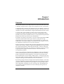
Chapter 1
Introduction
Overview
The CS1708
A
and CS1716
A
KVM switches are control units that allow access
to multiple computers from a single console (keyboard, mouse, and monitor).
A single CS1708
A
or CS1716
A
can control up to 8 or 16 computers. As many as
31 additional switches can be daisy chained to each other, so that up to 256 or 512
computers can all be controlled from a single keyboard-monitor-mouse console.
A custom ASIC (patent pending) provides an auto-sensing function that
recognizes the position of each station on the chain, eliminating the need to
manually set the position with DIP switches. A seven segment front panel LED
displays each station's position for easy identification.
For further convenience, the CS1708
A
/ CS1716
A
features high density SPHD
connectors instead of the usual 25-pin connectors. This space-saving
innovation allows a full, 16-port switch, to be installed in a 1U system rack.
Additionally, a front panel USB port is available for each computer to access
any peripherals connected to it on a one-at-a-time basis.
Setup is fast and easy; plugging cables into their appropriate ports is all that is
entailed. The CS1708
A
/ CS1716
A
supports both USB and PS/2 connections for
the console and computers; and because the CS1708
A
/ CS1716
A
intercepts
keyboard input directly, there is no software to configure, so there is no need
to get involved in complex installation routines or be concerned with
incompatibility problems.
Access to any computer connected to the installation is easily accomplished
either by manually pressing the front panel pushbutton port LEDs, entering
hotkey combinations from the keyboard, or by means of a powerful menu
driven multilingual on-screen display (OSD) system. A convenient auto-scan
feature also permits automatic scanning and monitoring of the activities of all
computers running on the installation on a one at a time basis.
By allowing a single console to manage all the attached computers, a CS1708
A
/ CS1716
A
installation: eliminates the expense of having to purchase a separate
keyboard, monitor, and mouse for each computer; saves all the space those
extra components would take up; saves on energy costs; and eliminates the
inconvenience and wasted effort involved in constantly moving from one
computer to another.

CS1708
A
/ CS1716
A
User Manual
2
Features
A single console controls up to 8 (CS1708
A
) or 16 (CS1716
A
) computers
Daisy chain up to 31 additional units – control up to 256 (CS1708
A
) or 512
(CS1716
A
) computers from a single console
Front panel USB port allows each computer to access USB peripherals*
Dual Interface – supports computers with PS/2 or USB keyboards and mice
Multiplatform support – Windows 2000/XP/Vista, Linux, Mac, and Sun
Supports USB keyboards for PC, Mac and Sun
Auto PS/2 and USB interface detection
USB / PS/2 keyboard and mouse emulation – computers boot even when
the console focus is elsewhere
Superior video quality – up to 2048 x 1536; DDC2B
Display Emulation Technology – stores the console monitor's EDID
(Extended Display Identification Data) to optimize display resolution
No software required – convenient computer selection via front panel
pushbuttons, hotkeys and multilingual on-screen display (OSD) menus
Auto-senses station's position on daisy chained installations; no need for
manual dip switch setting; front panel led indicates station's position
Port names automatically reconfigured when station sequence is changed
Two level password security; only authorized users view and control computers;
up to four users and an administrator with separate profiles for each
Auto Scan feature for monitoring user-selected computers
Broadcast mode; operations simultaneously performed on all selected computers
Hot pluggable – add or remove computers without having to power down
the switch
Buzzer on/off via hotkey and OSD
Firmware upgrades to all the chained KVM switches at the same time via
the daisy chain cable
Rack mountable in 19" system rack (1U)
* The USB peripheral function only works with USB cable set connections. It
will not work with PS/2 cable set connections.

Chapter 1. Introduction
3
Requirements
Console
The following hardware components are required for the KVM console:
A VGA, SVGA, or multisync monitor capable of displaying the highest
resolution provided by any computer in the installation.
A keyboard and mouse (USB or PS/2)
Computers
The following hardware components are required for each computer:
A VGA, SVGA, or multisync video graphics card with an HDB-15 port.
PS/2 mouse and keyboard ports (6-pin mini-DIN), at least one USB port.
Direct support Sun USB systems; or, for Sun legacy systems, an ATEN
CV130A Sun Console Converter.
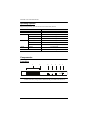
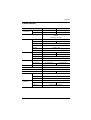
Cables
Substandard cables might damage the connected devices or degrade overall
performance. For optimum signal integrity and to simplify the layout use the
high quality custom cable sets described below.
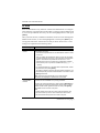
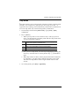
Function Length Part Number
KVM switch to KVM switch
(daisy chaining)
0.6 m
1.8 m
2L-1700
2L-1701
KVM switch to computer PS/2 1.2 m
1.8 m
3.0 m
6.0 m
1.8 m
2L-5201P
2L-5202P
2L-5203P
2L-5206P
2L-5702P
USB 1.2 m
1.8 m
3.0 m
5.0 m
2L-5201U
2L-5202U
2L-5203U
2L-5205U

CS1708
A
/ CS1716
A
User Manual
4
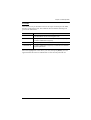
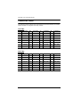
Operating Systems
Supported operating systems are shown in the table, below:
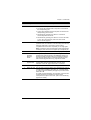
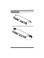
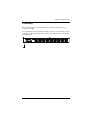
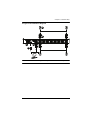
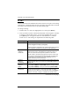
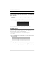
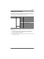
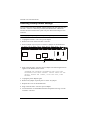
Components
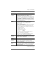
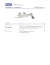
Front View
Note: The CS1716
A
is pictured above. The CS1708
A
front panel is the same
as the CS1716
A
, except that it has 8 KVM port LEDs instead of 16.
OS Version
Windows 2000 and higher
Linux RedHat 7.1 and higher
SuSE 8.2 and higher
Mandriva (Mandrake) 9.0 and higher
UNIX AIX 4.3 and higher
FreeBSD 4.2 and higher
Sun Solaris 8 and higher
Novell Netware 5.0 and higher
Mac OS 9 and higher
1 2 3 4 5 6 7

Chapter 1. Introduction
5
No. Component Description
1 Port LEDs These port selection pushbuttons each contain 2 LEDs.
An orange LED indicates that a computer is connected to
the corresponding port.
A green LED indicates that the computer connected to the
corresponding port has focus.
Simultaneously pressing port LEDs 1 & 2 resets the
console keyboard and mouse.
Simultaneously pressing port LEDs 7 & 8 on the CS1708
A
,
or 15 & 16 on the CS1716
A
, starts Auto Scan mode.
See F7: SCAN, page 37
2 Reset Button Pressing in this button performs a system reset. When the
system is reset, the CS1708
A
/ CS1716
A
beeps, and then the
KVM port LEDs flash in succession until the reset is
completed. After the reset is completed you can login again.
Note: This button is semi-rec essed and must be pushed with a
small object, such as the end of a paper clip or a ballpoint pen.
3 USB Port USB peripherals (flash drive, CD-ROM, etc.) plug into this port.
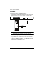
4Firmware
Upgrade
Recovery
Switch
During normal operation and while performing a firmware
upgrade, this switch should be in the NORMAL position. If a
firmware upgrade operation does not complete successfully,
this switch is used to perform a firmware upgrade recovery.
See Firmware Upgrade Recovery, page 56, for details.
5Firmware
Upgrade Port
The firmware upgrade cable that transfers the firmware
upgrade data from the administrator's computer to the
CS1708
A
/ CS1716
A
, plugs into this RJ-11 connector.
6 Power LED Lights to indicate that the unit is receiving power.
7 Station ID LED The CS1708
A
/ CS1716
A
station ID is displayed here. If this is
a single station installation (see page 13), or the first station
on a daisy chained installation (see page 16), the switch has a
station ID of 01.
On a daisy chained installation, the CS1708
A
/ CS1716
A
auto-
senses its position and displays the station ID that
corresponds to its place in the chain. (see Port ID Numbering,
page 22 for details).

CS1708
A
/ CS1716
A
User Manual
6
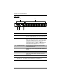
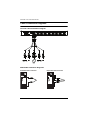
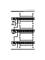
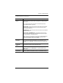
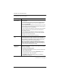
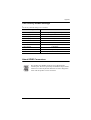
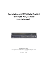
Rear View
Note: The CS1716
A
is pictured above. The CS1708
A
rear panel is the same as
the CS1716
A
, except that it has 8 KVM ports instead of 16.
No. Component Description
1 Daisy Chain Ports When daisy chaining units, the cables plug in here.
The port on the right is the Chain Out port; the one on
the left is the Chain In port.
2 KVM Ports The cables that link to the computers plug in here.
Note: The shape of these 15-pin connectors has been
specifically modified so that only custom KVM cables
designed to work with this switch can plug in.
(See Cables, page 3, for details.) Do NOT attempt to
use ordinary 15-pin VGA connector cables to link
these ports to the computers.
3 Grounding Terminal The grounding wire used to ground the CS1708
A
/
CS1716
A
attaches here.
4 Cable Tie Slot If you want to use a cable tie to gather the cables
together, you can run it through this slot to attach it to
the unit.
5 Power Jack The power adapter cable plugs in here.
6 Console Port The custom console cable set that is provided to
attach the console monitor, keyboard, and mouse
plugs in here.
1 2
43 5 6

7
Chapter 2
Hardware Setup
Overview
For convenience and flexibility that allows mixing PS/2 and USB interfaces,
the CS1708
A
/ CS1716
A
design utilizes custom KVM cables that serve as
intermediaries between the KVM switch and the connected computers.
A separate custom KVM cable is required for each computer connection. The
custom KVM cables are listed in the Cables section on page 3. Consult your
dealer to find out which custom KVM cables best fit your needs.
Before You Begin
1. Important safety information regarding the placement of this
device is provided on page 57. Please review it before proceeding.
2. To prevent damage to your installation from power surges or
static electricity. It is important that all connected devices are
properly grounded.
3. Make sure that the power to any device that you connect to the
installation has been turned off. You must unplug the power cords
of any computers that have the Keyboard Power On function.

CS1708
A
/ CS1716
A
User Manual
8
Stacking and Rack Mounting
The CS1708
A
/ CS1716
A
can be stacked on a desktop or rack mounted by a
variety of different methods in 1U of rack space. The procedures for each
method are described in the following sections.
Note: 1. Allow at least 5.1 cm on each side for adequate ventilation and
12.7 cm at the rear for power cord and cable clearance.
2. The standard rack mounting kit does not include screws or cage nuts.
If you need additional screws or cage nuts, contact your rack dealer.
3. For instructional purposes, the CS1708
A
is pictured in the diagrams
that follow. However, the CS1708
A
is the same as the CS1716
A
,
except that it has 8 KVM ports instead of 16.
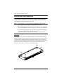
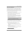
Stacking
The CS1708
A
/ CS1716
A
can be placed on any level surface that can safely
support its weight and the weight of the attached cables. Ensure that the surface
is clean and free of materials that can block the exhaust vents or otherwise
interfere with normal operation of the KVM switch. Peel the protective backing
off of the foot pads, and affix them to the bottom panel of the CS1708
A
/
CS1716
A
at the corners, as shown in the diagram below.

Chapter 2. Hardware Setup
9
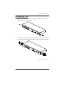
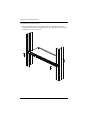
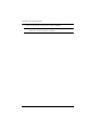
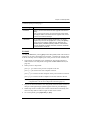
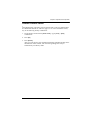
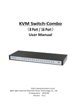
Rack Mounting – Front
1. Remove the screws from the left and right sides of the switch (2 screws
total) near the front of the switch.
2. Use the M3 x 8 Phillips hex head screws supplied with the rack mounting kit
to screw the rack mounting brackets into the sides near the front of the unit.
(Continues on next page.)

CS1708
A
/ CS1716
A
User Manual
10
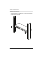
(Continued from previous page.)
3. Place the KVM switch in the rack. Position it so that the holes in the
mounting brackets line up with the holes in the rack. Secure the mounting
brackets to the front of the rack.
Page is loading ...
Page is loading ...
Page is loading ...
Page is loading ...
Page is loading ...
Page is loading ...
Page is loading ...
Page is loading ...
Page is loading ...
Page is loading ...
Page is loading ...
Page is loading ...
Page is loading ...
Page is loading ...
Page is loading ...
Page is loading ...
Page is loading ...
Page is loading ...
Page is loading ...
Page is loading ...
Page is loading ...
Page is loading ...
Page is loading ...
Page is loading ...
Page is loading ...
Page is loading ...
Page is loading ...
Page is loading ...
Page is loading ...
Page is loading ...
Page is loading ...
Page is loading ...
Page is loading ...
Page is loading ...
Page is loading ...
Page is loading ...
Page is loading ...
Page is loading ...
Page is loading ...
Page is loading ...
Page is loading ...
Page is loading ...
Page is loading ...
Page is loading ...
Page is loading ...
Page is loading ...
Page is loading ...
Page is loading ...
Page is loading ...
Page is loading ...
Page is loading ...
Page is loading ...
Page is loading ...
Page is loading ...
Page is loading ...
Page is loading ...
Page is loading ...
Page is loading ...
Page is loading ...
Page is loading ...
Page is loading ...
-
 1
1
-
 2
2
-
 3
3
-
 4
4
-
 5
5
-
 6
6
-
 7
7
-
 8
8
-
 9
9
-
 10
10
-
 11
11
-
 12
12
-
 13
13
-
 14
14
-
 15
15
-
 16
16
-
 17
17
-
 18
18
-
 19
19
-
 20
20
-
 21
21
-
 22
22
-
 23
23
-
 24
24
-
 25
25
-
 26
26
-
 27
27
-
 28
28
-
 29
29
-
 30
30
-
 31
31
-
 32
32
-
 33
33
-
 34
34
-
 35
35
-
 36
36
-
 37
37
-
 38
38
-
 39
39
-
 40
40
-
 41
41
-
 42
42
-
 43
43
-
 44
44
-
 45
45
-
 46
46
-
 47
47
-
 48
48
-
 49
49
-
 50
50
-
 51
51
-
 52
52
-
 53
53
-
 54
54
-
 55
55
-
 56
56
-
 57
57
-
 58
58
-
 59
59
-
 60
60
-
 61
61
-
 62
62
-
 63
63
-
 64
64
-
 65
65
-
 66
66
-
 67
67
-
 68
68
-
 69
69
-
 70
70
-
 71
71
-
 72
72
-
 73
73
-
 74
74
-
 75
75
-
 76
76
-
 77
77
-
 78
78
-
 79
79
-
 80
80
-
 81
81


Ask a question and I''ll find the answer in the document
Finding information in a document is now easier with AI
Related papers
Other documents
-
 Cables Direct KVM-512RK Datasheet
-
 KinAn LD2716 Owner's manual
-
 KinAn LH2708 Owner's manual
-
APC Switch AP5816 User manual
-
Zonet KVM3332 Installation guide
-
Tripp Lite KVM B005-008 User manual
-
 KinAn KC2108 Owner's manual
-
-
 KinAn XU0108 Owner's manual
-
 KVM SWITCHS KVM-1508XX User manual


