
Frymaster/Dean, a member of the Commercial Food Equipment Service Association,
recommends using CFESA Certified Technicians.
24-Hour Service Hotline 1-800-551-8633
*8196049*
February 2005
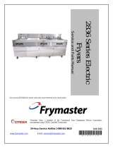
This manual is for models that have rounded elements and float switches.
2836 Series Electric Fryers
Service and Parts Manual

Please read all sections of this manual and retain for future reference.
NOTICE
This appliance is intended for professional use only and is to be operated by qualified
personnel only. A Frymaster/Dean Factory Authorized Service Center (FASC) or other qualified
professional should perform installation, maintenance, and repairs. Installation, maintenance,
or repairs by unqualified personnel may void the manufacturer’s warranty. See Chapter 1 of
this manual for definitions of qualified personnel.
NOTICE
This equipment must be installed in accordance with the appropriate national and local codes of
the country and/or region in which the appliance is installed.
NOTICE TO U.S. CUSTOMERS
This equipment must be installed in accordance with the appropriate national and local codes of
the country and/or region in which the appliance is installed.
NOTICE
Drawings and photos used in this manual are intended to illustrate operational, cleaning and
technical procedures and may not conform to onsite management operational procedures.
NOTICE TO OWNERS OF UNITS EQUIPPED WITH COMPUTERS
U.S.
This device complies with Part 15 of the FCC rules. Operation is subject to the following two
conditions: 1) This device may not cause harmful interference, and 2) This device must accept
any interference received, including interference that may cause undesired operation. While
this device is a verified Class A device, it has been shown to meet Class B limits.
CANADA
This digital apparatus does not exceed the Class A or B limits for radio noise emissions as set
out by the ICES-003 standard of the Canadian Department of Communications.
Cet appareil numerique n’emet pas de bruits radioelectriques depassany les limites de classe A
et B prescrites dans la norme NMB-003 edictee par le Ministre des Communications du Canada.
DANGER
Improper installation, adjustment, maintenance or service, and unauthorized alterations or
modifications can cause property damage, injury, or death. Read the installation, operating and
service instructions thoroughly before installing or servicing this equipment.

DANGER
The front ledge of the fryer is not a step. Do not stand on the fryer. Serious injury can result
from slips or contact with the hot oil.
DANGER
Do not store or use gasoline or other flammable vapors and liquids in the vicinity of this or any
other appliance.
DANGER
The crumb tray in fryers equipped with a filter system must be emptied into a fireproof container
at the end of frying operations each day. Some food particles can spontaneously combust if left
soaking in certain shortening material. Additional information can be obtained in the filtration
manual included with the system.
WARNING
No structural material on the fryer should be altered or removed to accommodate placement of
the fryer under a hood. Questions? Call the Frymaster/Dean Service Hotline at 1-800-551-8633.
WARNING
Do not bang fry baskets or other utensils on the fryer’s joiner strip. The strip is present to seal
the joint between the frypot. Banging fry baskets on the strip to dislodge shortening will distort
the strip, adversely affecting its fit. It is designed for a tight fit and should only be removed for
cleaning.
NOTICE
IF, DURING THE WARRANTY PERIOD, THE CUSTOMER USES A PART FOR THIS ENODIS
EQUIPMENT OTHER THAN AN UNMODIFIED NEW OR RECYCLED PART PURCHASED
DIRECTLY FROM FRYMASTER/DEAN, OR ANY OF ITS AUTHORIZED SERVICE CENTERS,
AND/OR THE PART BEING USED IS MODIFIED FROM ITS ORIGINAL CONFIGURATION, THIS
WARRANTY WILL BE VOID. FURTHER, FRYMASTER/DEAN AND ITS AFFILIATES WILL NOT BE
LIABLE FOR ANY CLAIMS, DAMAGES OR EXPENSES INCURRED BY THE CUSTOMER WHICH
ARISE DIRECTLY OR INDIRECTLY, IN WHOLE OR IN PART, DUE TO THE INSTALLATION OF
ANY MODIFIED PART AND/OR PART RECEIVED FROM AN UNAUTHORIZED SERVICE CENTER.

2836 Series Electric Fryers
Service & Parts Manual
TABLE OF CONTENTS
Page #
1. SERVICE PROCEDURES 1-1
1.1 General 1-1
1.2 Replace Computer/Controller 1-1
1.3 Replace Interface Board 1-2
1.4 Replace Transformer 1-3
1.5 Replace Temperature Probe 1-3
1.6 Replace Heating Element 1-6
1.7 Replace High-Limit 1-8
1.8 Replace Frypot 1-9
1.9 Replace Contactor (Latching or Heating) 1-10
1.10 Built-in Filter System Service Procedures 1-10
1.11 Basket Lift Service Procedures 1-12
1.12 Electric Interface Board Diagnostic Chart 1-15
1.13 Probe Resistance Chart 1-16
1.14 Element Wattage/Amperage Calculation Charts 1-16
1.15 Wiring Diagrams, Main – 480V (120V Controls) 1-17
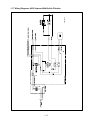
1.16 Wiring Diagrams, Modular Basket Lifts 1-18
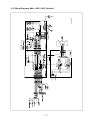
1.17 Wiring Diagrams, 480V Systems With Built-in Filtration 1-19

2836 Series Electric Fryers
Service & Parts Manual
TABLE OF CONTENTS (CONT.)
Page #
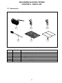
2. PARTS LIST 2-1
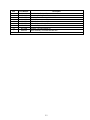
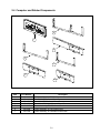
2.1 Accessories 2-1
2.2 Basket Lift Assembly (Modular) and Related Components 2-2
2.3 Cabinetry and Related Components 2-5
2.3.1 Cabinetry 2-5
2.3.2 Door Components 2-7
2.3.3 Dump Station Components 2-8
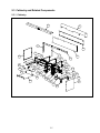
2.4 Computer and Related Components 2-9
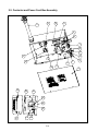
2.5 Contactor and Power Cord Box Assembly 2-10
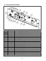
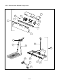
2.6 Component Box Assembly 2-12
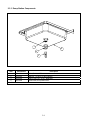
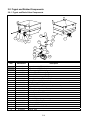
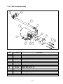
2.7 Filter Pan and Related Components 2-13
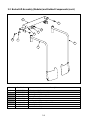
2.8 Frypot and Related Components 2-14
2.8.1 Frypot and Drain Valve Components 2-14
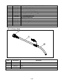
2.8.2 Oil Disposal Wand 2-15
2.8.3 Elements and Related Components 2-16
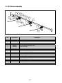
2.9 Oil Return Assembly 2-18
2.10 Filter Pump Assembly 2-19

2836 SERIES ELECTRIC FRYERS
CHAPTER 1: SERVICE PROCEDURES
1-1
1.1 General
Before performing any maintenance on your Frymaster/Dean Ultimate Electric fryer, you must
disconnect the electrical power supply.
When electrical wires are disconnected, it is recommended that they be marked in such a way as to
facilitate reassembly.
DANGER
Hot cooking oil or shortening will cause severe burns. Never attempt to move this appliance
when filled with hot cooking oil or shortening, or to transfer hot cooking oil or shortening
from one container to another.
DANGER
This equipment should be unplugged when servicing, except when electrical circuit tests are
required. Use extreme care when performing such tests.
This appliance may have more than one electrical power supply connection point.
Disconnect all power cords before servicing.
Inspection, testing and repair of electrical components should be performed by an
authorized service agent only.
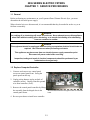
1.2 Replace Computer/Controller
1. Unscrew and remove two control panel
screws on control panel front. Swing the
panel open from the top.
2. Unplug wiring harness at plug on back of
controller (arrow). Unplug controller ground
wire from controller (circle).
3. Remove the control panel/controller by lifting
the assembly from the hinged slots in the
control-panel frame.
4. Reverse procedures to install new controller.
Wire harness/connector and ground wire on controller
back.

1-2
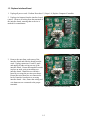
1.3 Replace Interface Board
1. Unplug all power cords. Perform Procedure 1.2, Steps 1-4, Replace Computer/Controller.
2. Unplug wire harness from the interface board
(arrow). Remove all wiring from the terminals of
the interface board, ensuring that each wire is
marked for reattachment.
3. Remove the nuts from each corner of the
interface board and slide the board from the
studs. Unplug connectors J1 and J2, mark
and unplug all other wiring on rear of the
interface board. Ensure that standoffs remain
in place on studs, prior to installing new
interface board. Install the new interface
board by reversing the previous procedures.
Ensure that wire harnesses are connected to
back of interface board prior to securing
interface board. Also, ensure that wiring and
wire harnesses are connected to the proper
terminals.
Wire harness/connector.
Nuts securing interface board (circles).

1-3
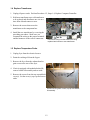
1.4 Replace Transformer
1. Unplug all power cords. Perform Procedure 1.2, Steps 1-4, Replace Computer/Controller.
2. Hold new transformer up to old transformer
to be replaced and disconnect one wire at a
time from old and connect to new.
3. Remove the screws that secure the
transformer to the component box.
4. Install the new transformer by reversing the
preceding procedures. Make sure you
reconnect the wiring to the proper terminals
and the harnesses to the correct connectors.
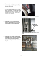
1.5 Replace Temperature Probe
1. Unplug fryer from the electrical source.
2. Drain the cooking oil from the frypot.
3. Remove the fryer from the exhaust hood to
gain access to the rear of the fryer.
4. If unit is equipped with modular basket lift,
remove basket lift assembly and set aside.
5. Remove the screws from the top cap and back
cover(s). Set the cover(s), top cap and screws
aside.
Screws securing back covers, top cap and basket
lift assembly.
Disconnect wiring from the transformer being
replaced and connect to new transformer.

1-4
6. Disconnect the wire harness containing the
probe wiring (arrows). It may be necessary
to remove the wire ties.
7. Use a pin-pusher (P/N 806-4855 or P/N 807-
0928—see Section 1.7) to remove the red and
white probe wires from the connector. Note
probe pin location in plug. Pull the probe
wires out of the insulation.
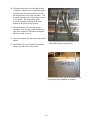
8. Remove the screw(s) securing the probe
bracket to the element. Remove the metal
wraps securing the probe to the element.
9. Remove the probe bracket and the securing
components from the probe bulb and element.
Thread the probe wire through the hole
(arrow) in the tilt plate assembly and remove
the probe.
Use a pin-pusher to remove probe wires from
connector (arrows).
Remove probe bracket screw and bracket to remove
p
robe.
Bracket Screw
Probe Bracket
Probe Bulb
Pull old probe wire through grommet to remove
probe.

1-5
10. Thread the new probe wire through the hole
in tilt plate. Place the new temperature probe
assembly onto the element and secure with
the bracket and screws removed earlier. Clip
the probe onto the rear of the element (arrow)
in two places. The temperature probe
assembly should be oriented in the same
manner as the probe being replaced.
11. Thread the probe wires into the harness
insulation. Note the pin positions and insert
pins in the connector. Reconnect the harness
and secure with a wire-tie.
12. Lower the element into the frypot with the lift
handle.
13. Install the back covers, basket lift assembly,
and top cap and secure with screws.
Secure probe bulb to the element back in two
places with metal wire wrap (arrow).
Install the cabinet backs, basket lift assembly, and
top cap after probe installation is complete.

1-6
1.6 Replace Heating Element
1. Perform Procedure 1.5, Replace Temperature Probe, Steps 1-7.
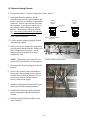
2. Unplug the element connectors for the
element being removed (right element- 6-pin
harness connector; left element- 9-pin harness
connector). Remove the element wires from
the connector. Press down on either side of
the connector while pulling up on the top
portion. The connector will open from the
top. Note wiring configuration in connector
before removing element wire pins. Pull all
wires from the connector.
3. Loosen conduit connector and pull element
wires through conduit.
4. Remove the screws securing the temperature
probe bracket from the element. Remove the
probe clamp (metal wire-wrap). Set the
temperature probe and probe-securing
components aside.
NOTE: Temperature probe removal is not
required if the left element is being replaced.
5. Disconnect the element springs from the tilt
brackets.
6. Remove the element clamps and hardware
before removing mounting-screws and nuts
on the defective element. Remove all wire-
ties securing element wiring, and then
remove element from frypot.
7. Install the replacement element in the frypot
and secure with the mounting hardware.
8. Reinstall the temperature probe and probe-
bracket components onto the replacement
element.
9. Route the element leads (terminals) to the
rear of the fryer
Top Portion
Harness
Connector
Closed
Harness
Connector
Open
Push in on tabs to release
top portion
Element mounting screws on tilt-plate front.
Loosen conduit connector here.

1-7
10. Secure element wiring with wire-ties.
11. Route the element wires through the conduit
and tighten conduit connector.
11. When replacing the left element (as viewed
from the rear of the fryer), use the 9-pin
connector, inserting the leads from the
replacement element. Ensure the pin
numbers match the numbers of the defective
element wires. When all pin terminals have
been fully inserted, close the connector by
sliding the halves together until the tabs snap
back into place (reverse procedure in this
section, Step 2). Check wire numbers to
ensure correct wiring of the replacement
element.
When replacing the right element (as viewed
from the rear of the fryer), follow the above
procedure, inserting pin terminals into the
corresponding holes in the 6-pin connector.
12. Connect the connectors, ensuring the latches
lock in place (arrow).
13. Install the temperature probe wires (marked
for re-assembly) in the corresponding pin
locations.
14. Reconnect the element springs to the tilt
brackets
15. Install the back covers, basket lift assembly,
and top cap and secure with screws.
16. Position fryer under exhaust hood.
Left Element—
9-Pin Connector
Right Element—
6-Pin Connector
Ensure the connection is complete and the
latches (arrow) are locked in place.
Ensure that the wires are properly routed and
secured.

1-8
1.7 Replace High-Limit
1. Perform Procedure 1.5, Replace Temperature
Probe, Steps 1-4.
2. Disconnect the wire harness containing the
high-limit wires.
3. Use a pin-pusher (P/N 806-4855 or P/N 807-
0928) to remove the two high-limit wires
from the wire harness connector (arrows).
Note pin location in connector before
removing wires.
4. Remove the high-limit from the frypot using
an open-end wrench or other suitable tool.
5. Apply Loc-Tite PST 567 sealant to the
replacement high-limit threads.
6. Screw the replacement high-limit into the
frypot and tighten to 170-180 inch-pounds
torque. DO NOT OVERTIGHTEN.
7. Insert the replacement high-limit wires into
the connector, ensuring each wire is in the
correct hole..
8. Reconnect the high-limit wire-harness
connector.
9. Install and secure the back cover(s).
10. Return fryer to operation.
Place wrench here when removing and installing
high-limit.
Using a pin-pusher, remove two high-limit wires
(arrows) from connector.

1-9
1.8 Replace Frypot
1. Perform Procedure 1.5, Replace Temperature Probe, Steps 1-7.
2. Perform Procedure 1.2, Replace Computer/Controller, Steps 1-3.
3. Perform Procedure 1.7, Replace High-Limit, Steps 1-4.
4. Disconnect the element wire harnesses.
5. If the fryer has a built-in filtration system, remove all the plumbing from the frypot, including
oil-return and drain plumbing.
6. Remove the screws securing the frypot to the front frame of the fryer.
7. Carefully lift the frypot from the cabinet.
8. Remove the drain valve from the old frypot and install on the new frypot.
9. Apply Loc-Tite Sealant PST 567 to the high-limit threads. Install high-limit into the new frypot.
10. Disconnect the tilt plate springs from the old frypot.
11. Remove the securing screws from the tilt plate. Lift the tilt plate/heating element assembly from
the old frypot and install on the new frypot.
12. Follow the preceding steps in reverse to install the new frypot into the fryer.
13. NOTE: Apply Loc-Tite Sealant PST 567 to all pipefittings prior to installation.

1-10
1.9 Replace Contactor (Latching or Heating)
1. Remove filter pan.
2. Remove cover to contactor box.
3. Identify faulty contactor. Remove all wiring
connected to the contactor terminals (circles)
inside the component box. Tape wire-pairs
together and mark each wire-set or wire for
reassembly.
4. Remove contactor-mounting screws (arrow)
and remove the contactor.
5. Install the new contactor and connect the
wiring removed in Step 3.
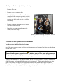
1.10 Built-in Filter System Service Procedures
Troubleshooting Built-In Filtration Systems
One of the most common errors is placing the filter paper on the bottom of the filter pan rather than
over the filter screen.
CAUTION
Ensure that the paper support screen is in place prior to filter paper placement and
filter pump operation. Improper screen placement is the major cause of filter system
malfunction.
Whenever the complaint is "the pump is running, but no oil is being filtered", check the installation
of the filter paper, and ensure that the correct size is being used. While you are checking the filter
paper, verify that the O-rings on the supply line connection are present and in good condition.
Missing or worn O-rings allow the pump to take in air, decreasing its efficiency. In addition, oil
leaks into the fryer and on the floor each time a frypot is filtered.
Remove contactor-mounting screws after removing
all wiring from the contactor (circles).

1-11
If the pump motor overheats, a circuit breaker will trip and the motor will not start until the breaker
is reset. If the pump motor does not start, press the white reset button located under the component
box, inside the cabinet.
If the pump starts after resetting the breaker, then something is causing the motor to overheat. A
major cause of overheating is when several frypots are filtered sequentially, thus overheating the
pump and motor. Allow the pump motor to cool at least 30 minutes before resuming operation, and
allow time for the motor to cool between sequential frypot filtering.
Pump overheating can be caused by:
• Solidified shortening in the pan or filter lines,
or
• Attempting to filter unheated oil or shortening.
Cold oil and shortening are more viscous, causing the pump motor to load up and overheat. Always
filter with the oil or shortening at operating temperature [~350°F (177°C)].
If the motor runs but the pump does not, there is a blockage in the pump. Incorrectly sized or
installed paper/pads will allow food particles and sediment to pass through the filter pan and into the
pump. When sediment enters the pump, the gears bind, causing the motor to overload, again
tripping the thermal overload. Shortening that has solidified in the pump will also cause it to seize,
with the same result.
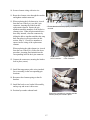
A pump seized by debris or hard shortening must be disassembled, cleaned, and then reassembled
before continuing use. Use the following procedure:
1. Disconnect power to the filter system.
2. Remove the front cover of the pump to access the gears inside (see illustration below- 8-GPM
pump shown), if the pump is accessible while still inside the cabinet.
Remove bolts to remove
pump cover.
Remove debris or hardened
shortening to free gears.

1-12
3. If the front cover is not accessible, the pump must be removed from the pump motor (remove
input/output plumbing from the pump prior to removing pump). Remove three setscrews from
the pump-shaft housing to disengage the pump from the motor. Remove the gears and
thoroughly clean all internal components. Ensure the inside of the pump housing is free of any
debris or hardened shortening before reassembling.
Failure to completely clean the inside
housing and ring gear will cause gear binding after reassembly.
Filter paper/pads that are the wrong size or installed incorrectly will also allow food particles and
sediment to pass through and clog the suction tube in the bottom of the filter pan. Particles large
enough to block the suction tube may indicate that the crumb tray is not being used.
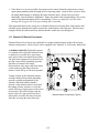
1.11 Basket Lift Service Procedures
Ultimate Electric Series fryers may optionally be equipped with automatic basket lifts to ensure
uniform cooking times. Electric fryers can be equipped with "modular" or "bell-crank" basket lifts.
A
modular basket lift (illustrated) consists
of a toothed rod to which the basket lift arm
is attached, a reversible-drive gear motor
and a pair of roller-activated microswitches.
The gear motor engages the teeth in the rod,
moving it up or down, depending upon the
direction of rotation of the motor.
Microswitches at the upper and lower limits
of movement stop the motor when the
basket is in the full up or full down position.
Timing circuitry in the controller initiates
and stops basket lift operation depending
upon the variables programmed by the
operator. When the product button is
pressed, or the manual control is activated,
the timing circuitry activates a coil in the
basket lift relay to supply power to the lower
microswitch. The microswitches stop the
motor at the lift’s upper and lower travel
limits and reverse the direction of current
flow thus reversing the motor direction.
Modular Basket Lift Assembly (Typical).

1-13
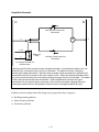
Simplified Schematic
M
H
N
Normally Closed Lower-limit
Microswitch
6
To computer/controller via
interface board
Basket Lift
Relay
3
1 or 4
5
Normally Open Upper-limit
Microswitch
When the product button is pushed on the computer/controller, current flows through a coil in the
basket lift relay, causing the lower circuit to be activated. The basket lift lowers, closing the
normally open upper-microswitch. When the lower normally closed microswitch is opened by the
downward moving lift rod, power to the motor ceases to flow. When the computer/controller times-
out, the current to the relay coil is interrupted, allowing the upper circuit to be activated. The basket
lift then raises and closes the lower microswitch. When the basket lift rod clears the upper
microswitch, the microswitch opens, and power to the circuit is interrupted, stopping the motor.
Pushing the product button or activating the manual control (if equipped) restarts the cycle.
Problems with the modular basket lift design can be grouped into three categories:
● Binding/jamming problems
● Motor and gear problems
● Electronics problems

1-14
BINDING/JAMMING PROBLEMS
Noisy, jerky or erratic movement of the lifts is usually due to lack of lubrication of the rods and their
bushings. Apply a light coat of Lubriplate
or similar lightweight white grease to the rod and
bushings to correct the problem.
With the modular basket lift, another possible cause of binding is improper positioning of the motor,
which prevents the gear from correctly engaging the teeth in the rod. To correct the problem, loosen
the screws that hold the motor in place and move it forward or backward until the rod has just
enough slack to be rotated slightly.
MOTOR AND GEAR PROBLEMS
With the modular basket lift, the most likely problem to be encountered in this category is erratic
motion of the lift due to a worn drive gear. Failure to keep the lift rod and bushings properly
lubricated will cause unnecessary wear of the gear. The problem is corrected by replacing the worn
gear.
If the lift cycles correctly but fails to remain in the up position (i.e., goes up, but then slowly settles
back down into the frypot), the problem is a failed motor brake. The motor must be replaced.
If power is reaching the motor but the motor fails to run, the motor is burned out and must be
replaced.
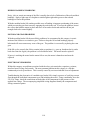
ELECTRONICS PROBLEMS
Within this category are problems associated with the relays, microswitches, capacitors, resistors,
interface board, wiring, and controls. The most common problem in this category is a lift that
continuously travels up and down. This is usually caused by a microswitch that is out of adjustment.
Troubleshooting the electronics of a modular-type basket lift is simply a process of verifying current
flow through the individual components up to and including the motor. Using a multimeter set to the
250 VAC range, check the connections on both sides of the component for the presence of the
applied line voltage. The accompanying simplified wiring diagrams identify the components and
wiring connection points.

1-15
1.12 Electric Interface Board Diagnostic Chart
The following diagram and charts provide ten quick system checks that can be performed using
only a multimeter.
Meter Setting Test Pin Pin Results
12 VAC Power 50 VAC Scale 1 of J2 3 of J2 12-16 VAC
24 VAC Power 50 VAC Scale 2 of J2 Chassis 24-30 VAC
*Probe Resistance R X 1000 OHMS 11 of J2 12 of J2 See Chart
Hi-Limit Continuity R X 1 OHMS 7 of J2 4 of J2 0 - OHMS
Latch Contactor Coil R X 1 OHMS 8 of J2 Chassis 3-10 OHMS
Heat Contactor Coil R X 1 OHMS 9 of J2 Chassis 18-25 OHMS
*Disconnect 15-Pin harness from the computer/controller before testing the probe circuit.
Note: The sealed relays
are not replaceable. If a
relay fails, the interface
board must be replaced.
Diagnostic LED Legend
CMP indicates power from 12V transformer
24 indicates power from 24V transformer
HI (RH) indicates output (closed) from right latch
relay
HI (LH) not applicable to Ultimate Electric fryers
HT (RH) indicates output from right heat relay
HT (LH) not applicable to Ultimate Electric fryers
AL (RH) indicates output (open) from right latch
relay
AL (LH) not applicable to Ultimate Electric fryers
1
23
4
5
6
8
7
9
10
11
12
13
14
15
1
2
3
4
5
6
7
8
9
10
11
12
1
2
3
4
5
6
7
8
9
10
11
12
K1
K2
K3 K4
Page is loading ...
Page is loading ...
Page is loading ...
Page is loading ...
Page is loading ...
Page is loading ...
Page is loading ...
Page is loading ...
Page is loading ...
Page is loading ...
Page is loading ...
Page is loading ...
Page is loading ...
Page is loading ...
Page is loading ...
Page is loading ...
Page is loading ...
Page is loading ...
Page is loading ...
Page is loading ...
Page is loading ...
Page is loading ...
Page is loading ...
Page is loading ...
-
 1
1
-
 2
2
-
 3
3
-
 4
4
-
 5
5
-
 6
6
-
 7
7
-
 8
8
-
 9
9
-
 10
10
-
 11
11
-
 12
12
-
 13
13
-
 14
14
-
 15
15
-
 16
16
-
 17
17
-
 18
18
-
 19
19
-
 20
20
-
 21
21
-
 22
22
-
 23
23
-
 24
24
-
 25
25
-
 26
26
-
 27
27
-
 28
28
-
 29
29
-
 30
30
-
 31
31
-
 32
32
-
 33
33
-
 34
34
-
 35
35
-
 36
36
-
 37
37
-
 38
38
-
 39
39
-
 40
40
-
 41
41
-
 42
42
-
 43
43
-
 44
44


Ask a question and I''ll find the answer in the document
Finding information in a document is now easier with AI
Related papers


Other documents
-
 Dean & Deluca BK1814 User manual
-
SPT 30211 Operating instructions
-
Diversitech 193025 Dimensions Guide
-
Scotsman Changing the Control Board from its Original Configuration to the AutoSentry System - 17-2813-01 Operating instructions
-
 SEYMOUR 82904 Operating instructions
-
Target Blu Eye 2 User manual
-
Weatherables AWCP-LVNEPTUNEKIT-4 Installation guide
-
Titan Rear ATV Mesh Rack Basket for Hunting User manual
-
 T & S Brass & Bronze Works B-0963 Datasheet
-
Hoshizaki HS-5249 User manual


