Page is loading ...

www.radialeng.com
SW8-USB
Auto-Switcher and USB Playback Interface
Specications and appearance are subject to change without notice.
Copyright © 2019 Radial Engineering Ltd.
Radial Engineering Ltd.
1588 Kebet Way, Port Coquitlam BC V3C 5M5
tel: 604-942-1001 • fax: 604-942-1010
email: [email protected] • web: www.radialeng.com
www.radialeng.com
True to the Music
Owner’s Manual

Radial SW8-USB Owner’s Manual
INTRODUCTION
Thank you for purchasing the SW8-USB, a unique backing track switcher and USB playback interface
that allows you to connect two computers to a professional audio system for playback, with the ability
to switch to the backup computer in an instant should a fault occur on the primary playback machine.
We encourage you to read through this manual to familiarize yourself with the many features available
on the SW8-USB, allowing you to get the most out of this powerful interface and auto-switching device. If
you have any questions not answered in this user guide, please visit our website at www.radialeng.com
for additional resources and frequently asked questions.
www.radialeng.com
Table of Contents
Overview..................................................................................................2
Features ..................................................................................................3-4
Powering the SW8-USB ..........................................................................5
Connecting the primary and backup computers ......................................5
Setting the digital audio resolution and selecting outputs........................6
Connecting the analog audio outputs ......................................................6
Operating in manual switch mode ...........................................................7
Using the JR-2 remote footswitch............................................................7
Auto-Switch mode overview ....................................................................8
Sending Tone via SPDIF to the Auto-Switch inputs .................................8
Sending MTC to the Auto-Switch inputs ..................................................8
Operating in Auto-Switch mode ...............................................................9
Synchronizing playback computers overview ..........................................10
Using the Start/Stop footswitch remote ...................................................10
Using an external MIDI device.................................................................10
Using the Sync Lock feature....................................................................11
Using the Alarm output ............................................................................12
Synchronizing multiple SW8-USB units...................................................12
Troubleshooting guide .............................................................................13-14
Warranty .................................................................................................. Back Cover
1
PERFORMANCE DISCLAIMER
The Radial SW8-USB is an electronic device designed to provide the means to backup other electronic
devices. However, like all electronics, the SW8 itself is not totally immune to malfunction. Because the
SW8 is designed to integrate with other devices to form a complete system, a critical malfunction may
not be obvious until the system is asked to perform. This makes it very important to test your complete
playback system before each performance to ensure your system is working as expected.
Radial Engineering Ltd. will not be held liable for any consequential or inconsequential costs or
damages associated with the use of the SW8-USB. It is understood that connecting, testing and
operating the SW8-USB, along with the application or misapplication, is the sole responsibility of the
end user. For more details refer to the Radial limited warranty.
!

True to the Music
Radial Engineering Ltd. SW8-USB™ Owner’s Manual
2
OVERVIEW
The SW8-USB is an eight channel switching device designed primarily for live concerts where backing tracks are
used to reinforce the performance. Should your primary playback source suffer a failure or dropout, the SW8-USB
can switch to a backup source to prevent any negative effects on the performance. This switching can be done
automatically by the SW8-USB, or it can be performed manually using a switch on the front panel or by remote
control.
Typical playback systems require a computer as the digital audio source, along with an audio interface in order
to provide analog audio outputs to feed the PA system. For a redundant playback system, the list of equipment
required is doubled: two computers, and two audio interfaces to pair with them. One of the advantages that the
SW8-USB provides over this typical setup is that it allows you to connect directly to your playback computers
over USB, eliminating the need for additional audio interfaces which in turn reduces the weight and cost of your
redundant system.
The SW8-USB is equipped with Type-B USB connectors and 24bit/192kHz digital audio converters that provide
eight channels of high quality audio playback over balanced XLR outputs. Designed to feed the PA system, these
mic-level outputs are transformer isolated to eliminate noise from ground loops, and they can also be set to line-
level operation. Additional line-level outputs are provided for local monitoring of your playback signals, with the
choice of DB25 or 1/4” TRS connections.
In addition to passing audio over USB, the SW8-USB is also able to function as a MIDI interface: providing you
with the ability to use the SW8-USB with show control systems to trigger lighting or video cues, or to control and
synchronize audio playback on your primary and backup computers. For larger shows that require more than eight
channels of audio playback, up to three SW8-USB units can be linked together for a total of 24 output channels.
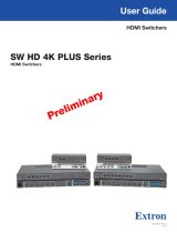
Typical stage setup for playing backing tracks through the SW8-USB
Front of House (FOH)
Primary Computer (A)Backup Computer (B) JR-2 Remote
(Optional)
Playback System
Control

3
True to the Music
Radial Engineering Ltd. SW8-USB™ Owner’s Manual
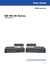
1. PSU A/B: Dual LEDs indicate that the SW8-USB is receiving power from each power supply. Only one connection is
required to power the SW8-USB, the other is provided for redundancy to eliminate loss of power.
2. MIC/LINE: Recessed switch determines whether the front panel XLRs are mic-level or line-level outputs. When set to mic (out
position), the XLR outputs are also transformer-isolated to reduce noise from ground loops. Red LED illuminates when set to line-
level operation.
3. AUTO: Recessed switch determines whether the SW8-USB switching is controlled manually by the user or set to Auto-Switch
mode where the SW8-USB will automatically select the B inputs should a fault be detected on the A side. Press in to engage Auto-
switch mode, the LED below will illuminate.
4. PLAYBACK ACTIVITY: Dual green LEDs illuminate to indicate that the SW8-USB is receiving MTC or tone via SPDIF - depending
on the Auto-Switch Input setting on the rear panel of the SW8-USB. Note that these LEDs will not light to signal audio playback.
5. MUTE: Latching switch with red LED indicator to mute the analog outputs of the SW8-USB. This will silence the XLR outputs, but
signal will still pass through the DB25 and TRS outputs on the rear panel, to allow for local signal monitoring.
6. STANDBY: Latching switch with ashing red LED indicator to direct the SW8-USB to hold on input A when in Auto-Switch mode,
regardless of whether MTC or tone via SPDIF is being received. This feature can also be activated remotely using the optional
JR-2 footswitch (by pressing MUTE on the JR-2).
7. INPUT SELECT: Latching switch allows you to select the active USB inputs. Green LED indicator for USB card A, amber LED
for USB card B. This switch is deactivated when the SW8-USB is in Auto-Switch mode, or when the optional JR-2 footswitch is
connected.
8. RESET: This momentary switch is used after a fault is detected, allowing the SW8-USB to switch back to the A inputs. Always
check that the Playback Activity A LED is illuminated (indicating good MTC or tone via SPDIF is being received) before pressing
this switch. (Used in Auto-Switch mode only)
9. ALARM: Flashing red LED indicator illuminates when a fault is detected on the primary playback computer (A), showing that the
SW8-USB is now playing back from the backup computer (B).
10. XLR OUTPUTS: Analog audio outputs playback from your primary or backup computer depending on the input select assignment.
These will output mic-level or line-level signals depending on the setting of the MIC/LINE switch.
11. GROUND LIFT: Lifts pin-1 on the XLR output to help eliminate hum and buzz from ground loops.
FRONT PANEL FEATURES
1 2 3 4 5 6 7 8 9 10 11

True to the Music
Radial Engineering Ltd. SW8-USB™ Owner’s Manual
4
REAR PANEL FEATURES
12 13 14 15 16 17 18 19 20 21
12. PSU A & B INPUTS: Connections for locking 4-pin power supplies (included). The PSUs for the SW8-USB are switching
supplies to allow for easy international usage.
13. MIDI IN/OUT: Allow you to to pass MIDI signal to and from the computer on the active USB connection. When SYNC LOCK is
disengaged, signal sent to the MIDI IN feeds both the primary and backup computers at once, allowing you to use an external MIDI
controller to trigger playback on both computers simultaneously.
14. SYNC LOCK: When engaged, this switch makes it possible to pass MIDI information from the primary computer to the backup
computer to allow for syncronized playback. Disengaging this switch allows an external MIDI controller or a footswich connected to
the START/STOP input to trigger playback on both computers simultaneously.
15. USB A & B: Type-B USB connections to directly connect your primary and backup playback computers for up to eight channels of
analog audio playback per SW8-USB. Compatible with Mac OS only, featuring 192kHz/24bit converters.
16. AUTO-SWITCH INPUT: Selects whether Tone via SPDIF or MTC is used for the auto-switch inputs of the SW8-USB. Tone (SPDIF)
should be used for the lowest latency when switching over to the B inputs.
17. START/STOP: 1/4” TRS connection allows you to send stop/start MMC signals to your computers to control and synchronize
playback. Can be used with standard contact closure footswitches such as the JR1-M remote footswitch.
18. DB25 OUTPUTS: Line-level outputs 1-8 over a DB25 multipin connection. These outputs are always active regardless of the
setting of the front panel MUTE switch, and they will follow the primary or backup computer along with the main XLR outputs.
19. 1/4” TRS OUTPUTS: Balanced output jacks are wired in parallel with the DB25 monitor outputs. These outputs operate at
line-level and will always be active regardless of the MUTE switch setting on the front panel.
20. JR-2 FOOTSWITCH INPUTS: XLR and 1/4” TRS connections allow the optional JR-2 remote footswitch to control the switching
and Standby functions of the SW8-USB. Standard 1/4” TS contact-closure footswitches and MIDI controllers with switching outputs
can also be used to select between the primary and backup computers.
21. ALARM: 1/4” TS connection from an internal relay can be used to turn on an external beacon when a dropout is detected at the
auto-switch input for computer A. This output can also be used to link multiple SW8-USB units together simultaneously.

True to the Music
Radial Engineering Ltd.
SW8-USB™ Owner’s Manual
5
Dual locking XLR power supplies included.
TYPE-B USB
Used to connect to the SW8-USB
TYPE-A USB
Fits older laptops and computers
EXCLUSIVELY
FOR MAC OS
Front panel PSU A and B indicators
TYPE-C USB
Fits newer laptops and computers
ACTIVE LEDs indicate
connection to each computer
GETTING STARTED
Before connecting to the SW8-USB, it is always best to turn your audio system levels down in order to prevent plug-
in transients that could damage more sensitive components such as high frequency drivers.
POWERING THE SW8-USB
The SW8-USB features redundant power supply inputs to protect against loss of power during use. Two power
supplies are included with locking 4-pin connectors to prevent accidental disconnection. These are switching power
supplies to allow for easy international use: simply swap out the IEC cable for the appropriate power connector
when travelling to a region with a different power grid. There is no power switch on the SW8-USB, once it is
connected to a power source it will be active and ready for use. Two front panel LEDs will indicate which PSU inputs
are connected and providing power to the SW8-USB.
CONNECTING THE PRIMARY AND BACKUP COMPUTERS
The SW8-USB features two Type-B USB connections, and requires two USB 2.0 cables to connect both of your
computers. Use a USB 2.0 Type-B to Type-A cable for older computers that feature this connector type, and a
USB 2.0 Type-B to Type-C cable for newer computers that only feature Type-C connections. USB adaptors and
Thunderbolt hubs can be used to make the connection from the SW8-USB to your computer, but for the most stable
results we recommend using a direct cable connection from the SW8-USB to each of your playback computers.
Your primary playback computer should be connected to the rear panel USB A jack, and the backup computer
to USB B. The SW8-USB is exclusively compatible with Mac OS, and should be recognized by your computer
immediately upon connection. Upon rst use, if your audio software does not recognize the SW8-USB, restart your
Mac while leaving the SW8-USB connected.

True to the Music
Radial Engineering Ltd. SW8-USB™ Owner’s Manual
6
SETTING THE DIGITAL AUDIO RESOLUTION AND SELECTING OUTPUTS
Once you’ve connected the SW8-USB to your primary and backup computers, use a Finder window to navigate
to Utilities > Audio MIDI Setup, and open the Audio Devices window. Set the bit depth and sample rate of the
SW8-USB to match the session settings of your Digital Audio Workstation (DAW). The SW8-USB can operate at
16 or 24bit resolution, with sample rates from 44.1kHz up to 192kHz.
CONNECTING THE ANALOG AUDIO OUTPUTS
The SW8-USB has two sets of analog audio outputs: the XLR connectors on the front panel to feed the main
PA system, and the rear panel DB25 and 1/4” TRS connectors for monitoring outputs at your playback control
station.
XLR OUTPUTS: The front panel XLR outputs feaure DI box transformers
that provide isolation to eliminate hum and buzz from ground loops when
connecting to distant PA systems. Individual ground lift switches are also
provided on each channel to further eliminate noise.
The XLR outputs provide balanced mic-level signals, allowing them to be fed
through stage snakes with other microphone outputs. You can bypass the
transformers on these channels if you wish to send line-level signals to the
PA system: this can be accomplished across all eight outputs using the global
XLR MIC/LINE switch.
You will notice that the SW8-USB is listed as a 10-output device, even
though there are only eight analog outputs. This is because outputs
9-10 are used to send Tone via SPDIF to activate the Auto-Switch
feature on the SW8-USB. See page 8 of this manual for more
details on using these outputs.
In your DAW, select the SW8-USB as your output device. You can
feed individual tracks to each of the eight mono outputs, or you
can send four stereo pairs of backing tracks to the audio outputs
of the SW8-USB as needed.
Changing audio settings in Audio MIDI Setup
Note: Up to three SW8-USBs can be simultaneously
connected to provide 24 channels of playback tracks
at a time. Please see the Synchronizing Multiple SW8-USB
Units section of the manual on page 12 for further details.
!
DB25 AND 1/4” TRS OUTPUTS: The rear panel outputs both operate at line-level, and are designed to be connected
to local monitoring systems to allow the operator to test the outputs and cue up tracks. These outputs will always be
active, so you can use the front panel MUTE switch to cut the XLR outputs to the PA system during testing, while
still hearing signal from the rear panel outputs. Use only one of the available connector types at any given time to
reduce the possiblity of encountering noise due to ground loops. The DB25 follows the Tascam pinout standard,
while the 1/4” outputs should be used with balanced TRS connectors.
Front of House (FOH)
Playback System Control
Front panel XLR MIC/LINE switch

True to the Music
Radial Engineering Ltd.
SW8-USB™ Owner’s Manual
7
MANUAL SWITCHING VS. AUTO SWITCHING
The SW8-USB can be used to manually select between the two playback computers, or it can be set to automatically
detect a drop-out or failure on your primary system and immediately switch to the backup system to ensure a
seamless performance. Even if you plan on using the SW8-USB in Auto-Switch mode, it is important to review how
to manually switch between inputs as this is useful when setting up and testing your playback system.
Primary Computer (A)
Backup Computer (B)
Manually switching to the backup computer
using the INPUT SELECT switch
OPERATING IN MANUAL SWITCHING MODE
In manual switching mode, the operator decides whether the A or B
inputs are selected. This is accomplished with the INPUT SELECT
switch. Note that three features on the SW8-USB will override this
switch and render it inactive:
1. The AUTO ON switch (front panel): This gives switching control over to the SW8-USB Auto-Switch function.
2. The JR-2 ON switch (rear panel): This allows a remote footswitch to select between the A and B inputs.
3. The STANDBY switch (front panel). This switch tells the SW8-USB to hold on the A inputs.
This feature is covered in detail in the Operating in Auto-Switch Mode section of the manual on page 9.
USING THE JR-2 REMOTE FOOTSWITCH
Manual switching can also be accomplished remotely using the optional JR-2
footswitch. The JR-2 can be connected using balanced XLR or 1/4” TRS cables: both
connector types are provided on the rear panel of the SW8-USB for convenience.
Once connected, the JR-2 ON switch (next to the XLR connector) must be engaged
for the remote to operate and to provide power to the LEDs - when the JR-2 is turned
on, the front panel INPUT SELECT switch will be inactive.
The JR-2 has two footswitches: the left ‘mute’ switch controls the STANDBY
feature of the SW8-USB, while the right footswitch will select between the A and B
inputs. The LED indicators on the JR-2 will sync with the front panel LEDs on the
SW8-USB, allowing you to check your settings at a glance on either device.
The Radial JR-2 Footswitch
Manually switching to the backup computer
using the JR-2 REMOTE footswitch
Primary Computer (A)
Backup Computer (B)
On
The INPUT SELECT switch on the front panel

True to the Music
Radial Engineering Ltd. SW8-USB™ Owner’s Manual
8
AUTO-SWITCH MODE OVERVIEW
The SW8-USB has the ability to automatically switch over to the backup (B) inputs should a dropout occur on your
primary (A) playback computer. This is accomplished by conguring each computer to send a constant signal during
playback to the Auto-Switch inputs of the SW8-USB. This signal can be either MTC (MIDI Time Code) or an audio
tone track that is fed to the SW8-USB via the SPDIF inputs. The PLAYBACK ACTIVITY LEDs on the front panel light
up when this signal is detected from each computer.
Should a failure occur on your primary computer, the SW8-USB will switch over to the backup (B) inputs and the
ALARM LED will ash. The SW8-USB will then remain on the B inputs until playback is restored on your primary
computer and the RESET switch is pressed. The STANDBY switch is used between songs to prevent the SW8-USB
from auto-switching when your primary playback computer is intentionally stopped.
When setting up for automatic switching, rst select
whether you will feed the Auto-Switch inputs using
MTC or Tone via SPDIF. Whichever method you choose
will need to be congured the same way on both the
primary and backup computers. For the lowest latency
when switching, we recommend using Tone via SPDIF
when in Auto-Switch mode.
The AUTO-SWITCH controls on the SW8-USB
SENDING TONE VIA SPDIF TO THE AUTO-SWITCH INPUTS
First ensure that the rear panel AUTO-SWITCH input selector is in the
‘out’ position to receive Tone via SPDIF. Using your preferred Digital Audio
Workstation (DAW), print a 1kHz sine wave that lasts the length of your audio
session le. Set this audio tone track to feed outputs 9-10, which are the
SPDIF input channels of the SW8-USB.
Tip: if using Avid ProTools, selecting a region on any track and pressing
Control+Option+Shift+3 will automatically print a 1kHz test tone across the
selection.
Begin playback in your DAW on the primary computer. You should see the
PLAYBACK ACTIVITY A LED illuminate to indicate that tone is being received
by the Auto-Switch input. Repeat these steps with your backup computer.
Tone
MTC
SENDING MTC TO THE AUTO-SWITCH INPUTS
To feed MTC (MIDI Time Code) to the Auto-Switch inputs, set the rear panel
AUTO-SWITCH input selector to the ‘in’ position. Then setup your Digital
Audio Workstation (DAW) to feed MTC to the SW8-USB. This will require
you to enable the MTC generate/transmit function in your DAW, and to
select the SW8-USB as the output destination. Refer to the user guide for
your DAW for details on where these settings are located (ProTools MTC
settings shown below).
Begin playback in your DAW on the primary computer. You should see the
PLAYBACK ACTIVITY A LED illuminate to indicate that good MTC is being
received by the Auto-Switch input. Repeat these steps with your backup
computer.
Select the SW8-USB as the MTC destinationEnable MTC generation in your DAW

True to the Music
Radial Engineering Ltd.
SW8-USB™ Owner’s Manual
9
The STANDBY switch
(Can also be controlled
using the JR-2 remote)
OPERATING IN AUTO-SWITCH MODE
Auto-Switch mode is activated by depressing the front panel AUTO switch,
illuminating the LED indicator below. Before engaging Auto-Switch mode, ensure
that you have sucessfully sent MTC or Tone via SPDIF to the SW8-USB from both
computers using the instructions on the previous page, as this is critical to the
operation of the Auto-Switch function.
After engaging Auto-Switch mode, begin playback on your primary (A) computer
only, so the PLAYBACK ACTIVITY A LED illuminates, then stop playback. You will
notice that even though the signal to the Auto-Switch input dropped out and the
PLAYBACK ACTIVITY A light turned off, the SW8-USB did not switch over to the
backup (B) computer.
The PLAYBACK ACTIVITY LEDs
This is because in Auto-Switch mode, the SW8-USB will only switch over to a backup computer that is actively
sending MTC or Tone via SPDIF to the Auto-Switch inputs. If the PLAYBACK ACTIVITY B LED is not illuminated, the
SW8-USB will assume that the backup playback system also has a fault, and it will not switch over to the B inputs.
In typical operation, the STANDBY switch will need to be engaged at the beginning and the end of each song, to
ensure the SW8-USB does not switch to the B inputs at the moment playback starts or stops. The SW8-USB is
able to detect a fault and switch inputs in as little as 10 milliseconds, so if the backup computer begins playback
even slightly before the primary computer, it will cause the SW8-USB to indicate there is an error and switch to the
B inputs.
Typical operation:
Both LEDs are lit
indicating good
signal at both
Auto-Switch inputs.
Fault on machine A:
Dropout on A and
good signal on B will
cause the SW8-USB
to switch to input B.
No signal present:
With no signal at
either Auto-Switch
input, the SW8-USB
will not switch over.
When STANDBY is engaged, the AUTO ON LED will turn off to indicate that the
operator has temporarily overriden the Auto-Switch feature, and the SW8-USB
will hold on the A inputs, regardless of the status of the PLAYBACK ACTIVITY
LEDs. Once the STANDBY function is disengaged, the SW8-USB will return to
normal Auto-Switch operation and switch to the backup inputs should your primary
playback system fail.
Note: You can avoid the requirement to engage the STANDBY switch
when using Tone via SPDIF to feed the Auto-Switch inputs. On the backup
(B) computer, trim 1 second from the start and end of each printed tone track in
your DAW. This will prevent the SW8-USB from unintentionally switching to the
backup inputs at the start and end of each song.
!
When a fault occurs during playback, the SW8-USB will switch to the B inputs and the ALARM LED will ash. Before
reaching for the RESET or STANDBY switches after an error, always ensure that your primary playback computer is
(1) playing back at the correct point in the song, and (2) generating good MTC or Tone via SPDIF so that the
PLAYBACK ACTIVITY A LED is lit.
Note that pressing the RESET switch will tell the SW8-USB to revert back to the A computer for playback, but if the
PLAYBACK ACTIVITY A LED is not lit, then the SW8-USB will automatically switch back to the B computer when the
RESET button is released. In most cases, after a fault you will want to wait until the end of the current song before
switching back to the A inputs.
The AUTO ON switch

True to the Music
Radial Engineering Ltd. SW8-USB™ Owner’s Manual
10
SYNCHRONIZING PLAYBACK COMPUTERS OVERVIEW
The SW8-USB provides multiple options for synchronizing playback between your primary and backup computers:
The START/STOP footswitch input allows a remote control to trigger the SW8-USB to send start/stop MMC transport
commands to both computers, MIDI IN allows an external MIDI device to trigger both computers for playback, or you
can have the primary computer send MIDI information over USB to the backup computer to enable synchronization
by using the SYNC LOCK feature.
USING THE START/STOP FOOTSWITCH REMOTE
The SW8-USB can be connected to a footswitch that will enable it to send start and stop MMC (MIDI Machine
Control) transport commands to your playback computers, allowing you to begin playback remotely and ensure that
both machines start each track simultaneously.
Out
Disengage SYNC LOCK to send MMC
commands to both computers simultaneously
The Radial JR1-M footswitch
The Radial JR1-M remote footswitch can be used for this purpose, or any standard
non-latching, contact closure footswitch can also be employed. Connect the footswitch
to the START/STOP input on the rear panel using a 1/4” TRS cable. If using the JR1-M,
set the recessed PASSIVE/ACTIVE switch to PASSIVE mode. When connecting a
remote footswitch to control playback, ensure that the rear panel SYNC LOCK switch
is in the ‘out’ position - this allows both your primary and backup computers to receive
MMC transport commands from the SW8-USB.
In your Digital Audio Workstation (DAW) on each
computer, enable ‘MIDI Machine Control remote’
or ‘Listen to MMC Input’ to allow incoming MMC
commands to be received.
The rst time you press the JR1-M footswitch, it will trigger the SW8-USB
to send a ‘start’ MMC transport command to each of your computers.
The second time the footswitch is pressed, the SW8-USB will send a
‘stop’ MMC command to both computers. The SW8-USB will continue
to alternate between sending start and stop commands in this manner.
When using the START/STOP feature to control playback during a
performance, avoid pressing the spacebar or the return key on each
computer to locally start or stop playback. The reason for this is that
the SW8-USB will always alternate between sending start and stop
MMC commands. So if you use the JR1-M to send a start message to
your computers, and then use the spacebar on each machine to stop
playback, the next time you press the remote footswitch you will be
sending a second ‘stop’ command to both DAWs.
In some DAWs, this second ‘stop’ command may relocate the playback cursor to the beginning of the session. Most
of the time when alternating between using the JR1-M and the spacebars on your computers, the result will be that
you will have to press the JR1-M footswitch twice in order to send the intended MMC command to your computers.
USING AN EXTERNAL MIDI DEVICE
An external MIDI controller can also be used to trigger playback on both computers simultaneously. To accomplish
this rst disengage the SYNC LOCK switch as mentioned above and connect your external device to the MIDI IN
jack on the rear panel. You will also need to enable the SW8-USB as a MIDI input device in the DAWs on both
playback computers, and congure the peripherals settings in each DAW to allow for external transport control.
Enabling MMC inputs in ProTools

True to the Music
Radial Engineering Ltd.
SW8-USB™ Owner’s Manual
11
USING THE SYNC LOCK FEATURE
SYNC LOCK on the SW8-USB allows the primary (A) computer to
pass MTC (MIDI Time Code) to the backup (B) computer over the USB
connection. This makes it possible to synchronize both computers by
setting the backup computer to start playback when MTC is recieved, so
that you only have to press play on your primary computer to start both
machines simultaneously.
To use SYNC LOCK, rst engage the recessed switch on the rear panel
of the SW8-USB.
Engage SYNC LOCK to pass MIDI
information from your primary (A) computer to
the backup (B) computer
In
On your primary (A) computer, change the settings in your
Digital Audio Workstation (DAW) to select the SW8-USB as your
MTC destination, and to generate MTC upon playback. You may
need to refer to the manual for your DAW to nd these settings.
You can check that your primary computer is sucessfully
generating MTC by setting the rear panel AUTO-SWITCH input
selector to the ‘in’ position. When you begin playback on your
primary computer, the front panel PLAYBACK ACTIVITY A LED
will illuminate if the SW8-USB is receiving good MTC.
On the backup (B) computer, change your DAW synchronization
settings so that the SW8-USB is selected as the MTC source. You
will also need to set your DAW to syncronize to incoming timecode:
in ProTools this is accomplished by pressing Command+J to
enable online playback, or by pressing the clock face icon in the
transport window.
When syncronizing your backup computer to follow the primary
computer via SYNC LOCK, it is important to ensure that the
backup system will continue playback even if the primary system
fails. This type of synchronization is known as Jam Sync, and it
means that the backup system continues to generate MTC on its
own even if the original MTC source fails or becomes unstable.
Not all Digital Audio Workstations (DAWs) offer this feature - if
this is the case for your preferred DAW, use one of the other
synchronization methods described in this manual.
One nal setting to check is the timecode frame rate, which is
usually found in your session settings window. The value of this
setting is not important to the operation of the SW8-USB (24, 25,
29.97, and 30fps can all be used), but it is critical that both of your
DAWs are set to the same timecode rate to ensure syncronization
via SYNC LOCK.
Primary (A) Computer settings
Select the SW8-USB as the MTC destination
Enable MTC generation in your DAW
Set your DAW to sync to incoming timecode
Backup (B) Computer settings
Enable Jam Sync to ignore timecode dropouts
Select the SW8-USB as the MTC source

True to the Music
Radial Engineering Ltd. SW8-USB™ Owner’s Manual
12
Linking multiple SW8-USB units using 1/4” TRS cables
On
USING THE ALARM OUTPUT
When in Auto-Switch mode, the SW8-USB can seamlessly switch over to the backup (B) computer. This can occur
without a noticeable gap in audio playback, so unless you were looking at the front panel of the SW8-USB you
wouldn’t know that the switch had occurred and you were running on your backup system.
For this reason, the SW8-USB is equipped with an ALARM output that can be connected to an external circuit to
trigger a beacon or an audible alarm that can be easier to identify during a performance. This output features a
special 24 Volt relay that can be connected to an external circuit and power supply as shown below, with a standard
1/4” TS jack connected to the ALARM output.
Normally, the relay is in an ‘open’ state preventing current from owing through the external circuit and activating the
beacon. However, when the SW8-USB detects a dropout at the auto-switch input and switches over to the backup
(B) computer the relay closes, allowing current to ow through the external alarm, while simultaneously illuminating
the ALARM LED on the front panel. Once good signal is again fed to the Auto-Switch input and the RESET button
is pressed, the SW8-USB switches back to the primary (A) inputs and the external alarm turns off.
Using the ALARM output to trigger an external device
DC Power Supply
5-12 Volts
External Beacon
SYNCHONIZING MULTIPLE SW8-USB UNITS
Up to three SW8-USB units can be linked together to provide as many as 24 channels of simultaneous playback
tracks for larger productions, while retaining the powerful switching capabilities of the SW8-USB. You can connect
each SW8-USB directly to each computer with USB cables, or you can use two hubs (one for the primary computer,
one for the backup) to free up available ports on your computers. If using a hub to connect multiple SW8-USBs,
ensure it is equipped with the Thunderbolt
TM
protocol - this is required to provide a high enough transfer speed for
connection to multiple SW8-USB units simultaneously.
To begin, connect your rst SW8-USB to the primary computer and open the Audio Devices window in Audio MIDI
Setup. Press the ‘+’ button in the lower left corner of the window and select ‘Create Aggregate Device’ - a new
aggregate device will appear on the left side that you can rename by double-clicking on it. With this new aggregate
device selected, check on the ‘Use’ box to select the connected SW8-USB. Connect the next two SW8-USB units
to your computer in turn, checking the box next to the name ‘Radial SW8-USB’ each time to add them to the
aggregate. In your Digital Audio Workstation, select your aggregate device as the enabled output device.
To ensure all three SW8-USB units switch
simultaneously, treat the rst SW8-USB as the
master unit and use its ALARM output to control
the remaining units in the chain. Connect a 1/4”
TRS cable from the ALARM output on the rst
SW8-USB to the JR-2 IN on the second unit, and
repeat this process for the third SW8-USB.
Ensure that the JR-2 ON switches are engaged
on the second and third SW8-USB, and that front
panel AUTO ON and STANDBY functions are
disengaged on these units.

True to the Music
Radial Engineering Ltd.
SW8-USB™ Owner’s Manual
SW8-USB TROUBLESHOOTING GUIDE
PSU A or B LED does not light up.
Check that both your power supplies are plugged in and using the correct adaptor cable for your region.
USB A and B LEDs are lit on the back panel of the SW8-USB even though the device is not powered.
This is normal operation for the SW8-USB, the USB cards in the device that connect to your computers are bus
powered, meaning that the connected computer provides the power to the USB converter. This means that these
will remain powered even if you unplug the PSUs for the SW8-USB.
The Playback Activity LEDs are always off even though I can hear audio from both computers.
The Playback Activity LEDs will only turn on if you are feeding MTC or Tone via SPDIF from each computer to the
SW8-USB, which allows for auto switching to occur. These LEDs will not indicate audio output from channels 1-8
on either computer. To monitor the audio outputs from your active computer, use the 1/4” TRS or DB25 outputs on
the rear panel of the SW8-USB.
I can still hear playback from my computer even when the Mute switch is pressed.
The front panel Mute switch will cut the XLR outputs which will normally be feeding the PA system, but it will leave
the rear panel 1/4” TRS and DB25 outputs active. This allows you to monitor playback and cue up your track if
necessary before sending it out to the audience.
When the Alarm LED is ashing, pressing Reset will not allow me to switch back to the A inputs.
When the SW8-USB is in auto-switching mode, it will stay on the B inputs once a dropout has been detected from
the A computer. Pressing Reset will normally allow you to switch back to the A inputs, but only if good Tone via
SPDIF or MTC information is being received from the A computer. Check that the Playback Activity A LED is lit
before pressing Reset. To switch back to the A inputs even if the Playback Activity A LED is not lit, use the Standby
switch.
The Auto ON LED is off even though the switch is pressed in.
Whenever the Standby switch is engaged on the front panel of the SW8-USB or on the JR-2 remote (labeled as
Mute on the remote), this will turn off the AUTO ON LED to indicate that the user has temporarily overridden the
auto-switching function. Once the Standby switch is deactivated when in Auto-Switch mode, the AUTO ON LED
should illuminate.
The front panel Input Select switch has no effect.
There are three cases where the front panel Input Select switch is defeated; if the JR-2 remote is connected and the
ON switch on the rear panel is activated, if the Auto switch is engaged, or if the Standby switch is engaged. Ensure
that all three of these features are deactivated to use the local Input Select feature on the front panel.
The JR-2 footswitch won’t allow me to select between the A or B inputs.
Check that STANDBY and AUTO ON are disengaged on the front panel, and the rear panel JR-2 ON is engaged.
The JR-2 footswitch won’t allow me to put the SW8-USB into standby.
Check that the STANDBY switch on the front panel is disengaged, and the rear panel JR-2 ON is engaged.

True to the Music
Radial Engineering Ltd. SW8-USB™ Owner’s Manual
The JR-2 LEDs illuminate, but they won’t allow me to switch the inputs of the SW8-USB and Standby mode
is always engaged.
Check that you are using a 1/4” TRS balanced cable to connect the JR-2, these symptoms occur when a 1/4” TS
unbalanced cable is connected to the JR-2 input.
The SW8-USB is stuck on Input B and the Alarm LED is not ashing.
Check that the rear panel JR-2 ON switch is turned off, if this switch is engaged without a footswitch connected to
the JR-2 input it will cause this error state.
The SW8-USB is not recognized by my computer.
Ensure that you are using a Mac computer with the SW8-USB, Windows machines are not supported. If the SW8-
USB does not show up in Audio MIDI Setup, try restarting your computer with the SW8-USB connected to it.
I hear hum and buzz on my playback tracks through the PA system.
If you encounter ground loop noise including hum and buzz, engage the ground lift switches on the front panel next
to each XLR output. If this doesn’t fully solve the problem, ensure the MIC/LINE switch is disengaged to select MIC.
I’m using an external MIDI trigger to start playback on both computers at the same time, but it will only work
on the primary computer.
Check the SYNC LOCK switch on the rear panel, this needs to be in the ‘out’ position to allow an external trigger to
affect both computers.
The Playback LEDs will not light when I’m trying to feed MTC or Tone via SPDIF to the auto-switch inputs.
First ensure that you have the correct setting on the Auto-Switch button on the rear panel of the SW8-USB. Move
this button to the ‘in’ position for MTC, and ‘out’ for Tone via SPDIF. If using MTC, ensure that you have enabled
the generate MTC function in your DAW, and select the SW8-USB as your MTC destination. For Tone via SPDIF,
ensure your printed tone track is being fed to both inputs 9 and 10, and try turning up the volume of this track until
the front panel LED illuminates.
I have a JR-1M footswitch connected to the Start/Stop input jack, but it doesn’t affect playback on one or
both of my computers.
Check that the SYNC LOCK switch is disengaged, and check that each DAW is set to ‘listen to MMC input / enable
MMC remote’.

www.radialeng.com
Radial SW8-USB™ Owner’s Manual - Part # R870 1048 / 07-2019
Specications and appearance are subject to change without notice.
Radial Engineering Ltd.
1588 Kebet Way, Port Coquitlam BC V3C 5M5
tel: 604-942-1001 • fax: 604-942-1010
email: [email protected] • web: www.radialeng.com
RADIAL ENGINEERING LTD.
3 YEAR TRANSFERABLE WARRANTY
RADIAL ENGINEERING LTD. (“Radial”) warrants this product to be free from defects in material and work-
manship and will remedy any such defects free of charge according to the terms of this warranty. Radial will
repair or replace (at its option) any defective component(s) of this product (excluding nish and wear and
tear on components under normal use) for a period of three (3) years from the original date of purchase. In
the event that a particular product is no longer available, Radial reserves the right to replace the product
with a similar product of equal or greater value. To make a request or claim under this limited warranty, the
product must be returned prepaid in the original shipping container (or equivalent) to Radial or to an autho-
rized Radial repair center and you must assume the risk of loss or damage. A copy of the original invoice
showing date of purchase and the dealer name must accompany any request for work to be performed
under this limited and transferable warranty. This limited warranty shall not apply if the product has been
damaged due to abuse, misuse, misapplication, accident or as a result of service or modication by any
other than an authorized Radial repair center.
THERE ARE NO EXPRESSED WARRANTIES OTHER THAN THOSE ON THE FACE HEREOF AND DE-
SCRIBED ABOVE. NO WARRANTIES WHETHER EXPRESSED OR IMPLIED, INCLUDING BUT NOT
LIMITED TO, ANY IMPLIED WARRANTIES OF MERCHANTABILITY OR FITNESS FOR A PARTICULAR
PURPOSE SHALL EXTEND BEYOND THE RESPECTIVE WARRANTY PERIOD DESCRIBED ABOVE
OF THREE YEARS. RADIAL SHALL NOT BE RESPONSIBLE OR LIABLE FOR ANY SPECIAL, INCIDEN-
TAL OR CONSEQUENTIAL DAMAGES OR LOSS ARISING FROM THE USE OF THIS PRODUCT. THIS
WARRANTY GIVES YOU SPECIFIC LEGAL RIGHTS, AND YOU MAY ALSO HAVE OTHER RIGHTS,
WHICH MAY VARY DEPENDING ON WHERE YOU LIVE AND WHERE THE PRODUCT WAS PUR-
CHASED.
To meet the requirements of California Proposition 65, it is our responsibility to inform you of the following:
WARNING: This product contains chemicals known to the State of California to cause cancer, birth defects
or other reproductive harm.
Please take proper care when handling and consult local government regulations before discarding.
All trademarks belong to their respective owners. All references to these are for example only and are
not associated with Radial.
/