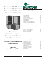
ClimateMaster TT, TS, TC, TR Install Manual
- Category
- Heat pumps
- Type
- Install Manual

Tranquility
27
®
(TT) Series
Tranquility
20 (TS) Series
Tranquility 16
(TC) Series
Tranquility
(TR) Series
Commercial
Horizontal & Vertical
Packaged Water-Source
Heat Pumps - 60 Hz
INSTALLATION, OPERATION
& MAINTENANCE
97B0075N01
Rev.: 03 January, 2011
Table of Contents
Model Nomenclature - General Overview For
All H & V Series 3
General Information 4
Unit Physical Data 6
Horizontal Installation 10
Field Conversion of Air Discharge 12
Vertical Installation 14
Piping Installation 16
Water-Loop Heat Pump Applications 17
Ground-Loop Heat Pump Applications 18
Ground-Water Heat Pump Applications 20
Water Quality Standards 22
Electrical - Line Voltage 23
Electrical - Line Voltage 24
Electrical - Power Wiring 34
Electrical - Power & Low Voltage Wiring 35
Electrical - Low Voltage Wiring 36
Electrical - Thermostat Wiring 38
Blower Performance Data 39
ECM Blower Control 46
Typical Wiring Diagrams 51
CXM Controls 52
DXM Controls 53
Safety Features - CXM and DXM Controls 55
ClimaDry Modulating Reheat Option 57
Unit Starting and Operating Conditions 60
Piping System Cleaning and Flushing 61
Unit and System Checkout 62
Unit Start-Up Procedure 63
Preventive Maintenance 77
Functional Troubleshooting 78
Start-Up Log Sheet 80
Functional Troubleshooting 81
Warranty (U.S. & Canada) 82
Revision History 84

C L I M A T E M A S T E R W A T E R - S O U R C E H E A T P U M P S
Packaged Units
R e v. : 0 3 Janu a r y, 2 0 1 1
2
C l i m a t e M a s t e r Wa t e r - S o u r c e H e a t P u m p s
This Page Intentionally Left Blank

T H E S M A R T S O L U T I O N F O R E N E R G Y E F F I C I E N C Y
Packaged Units
R e v. : 0 3 J a n u a r y, 2 0 1 1
3
c l i m a t e m a s t e r. c o m
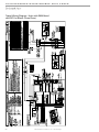
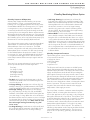
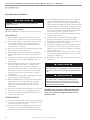
Model Nomenclature
General Overview For All H & V Series
Note: Above model nomenclature is a general reference. Consult individual engineering guides for detailed information.
A0 2 6 CG 1 0 C L K
4 5 6 7
8
9 10 11 12 13 14
Unit Size, MBtuh
Return Air
Voltage
Controls
Revision Level
Heat Exchanger & Valve Options
See model nomenclature for specific options
Cabinet Insulation
TT
1 2
TT = Tranquility Two Stage Scroll
Model Type
V
3
V = Vertical Upflow
Configuration
See model nomenclature for specific options
L = Left Return
R = Right Return
See model nomenclature for specific options
Water Circuit Options
S
15
S = Standard
Standard
H = Horizontal
D = Vertical Downflow
Supply Air & Motor Option
Rev.: 7/22/09B
TS = Tranquility Single Stage Scroll
TR = Tranquility High Efficiency
See model nomenclature for specific options
NOTE: Some options/configurations not availaible on all series. Please consult Engineering Guides for model specific options.
G = 208-230/60/1
H = 208-230/60/3
F = 460/60/3
E = 265/60/1
N = 575/60/3
Standard
LON DDC
MPC DDC
60Hz Units
CXM DXM
C
L
D
M
N P
TC = Tranquility Compact

C L I M A T E M A S T E R W A T E R - S O U R C E H E A T P U M P S
Packaged Units
R e v. : 0 3 J a n u a r y, 2 0 1 1
4
C l i m a t e M a s t e r Wa t e r - S o u r c e H e a t P u m p s
General Information
WARNING! To avoid the release of refrigerant into the
atmosphere, the refrigerant circuit of this unit must be
serviced only by technicians who meet local, state, and
federal prociency requirements.
WARNING! All refrigerant discharged from this unit must
be recovered WITHOUT EXCEPTION. Technicians must
follow industry accepted guidelines and all local, state, and
federal statutes for the recovery and disposal of refrigerants.
If a compressor is removed from this unit, refrigerant circuit
oil will remain in the compressor. To avoid leakage of
compressor oil, refrigerant lines of the compressor must be
sealed after it is removed.
CAUTION! To avoid equipment damage, DO NOT use
these units as a source of heating or cooling during the
construction process. The mechanical components and lters
will quickly become clogged with construction dirt and debris,
which may cause system damage.
WARNING!
WARNING!
WARNING!
CAUTION!
Safety
Warnings, cautions, and notices appear throughout this
manual. Read these items carefully before attempting any
installation, service, or troubleshooting of the equipment.
DANGER: Indicates an immediate hazardous situation,
which if not avoided will result in death or serious injury.
DANGER labels on unit access panels must be observed.
WARNING: Indicates a potentially hazardous situation,
which if not avoided could result in death or serious injury.
CAUTION: Indicates a potentially hazardous situation or
an unsafe practice, which if not avoided could result in
minor or moderate injury or product or property damage.
NOTICE: Notification of installation, operation, or
maintenance information, which is important, but which is
not hazard-related.
WARNING! The EarthPure® Application and Service Manual
should be read and understood before attempting to service
refrigerant circuits with HFC-410A.
Inspection - Upon receipt of the equipment, carefully
check the shipment against the bill of lading. Make sure
all units have been received. Inspect the packaging of
each unit, and inspect each unit for damage. Ensure that
the carrier makes proper notation of any shortages or
damage on all copies of the freight bill and completes a
common carrier inspection report. Concealed damage
not discovered during unloading must be reported to the
carrier within 15 days of receipt of shipment. If not filed
within 15 days, the freight company can deny the claim
without recourse.
Note: It is the responsibility of the purchaser to file all
necessary claims with the carrier. Notify your equipment
supplier of all damage within fifteen (15) days of
shipment.
Storage - Equipment should be stored in its original
packaging in a clean, dry area. Store units in an upright
position at all times. Stack units a maximum of 3 units
high.
Unit Protection - Cover units on the job site with either
the original packaging or an equivalent protective
covering. Cap the open ends of pipes stored on the
job site. In areas where painting, plastering, and/or
spraying has not been completed, all due precautions
must be taken to avoid physical damage to the units
and contamination by foreign material. Physical damage
and contamination may prevent proper start-up and may
result in costly equipment clean-up.
Examine all pipes, fittings, and valves before installing
any of the system components. Remove any dirt or debris
found in or on these components.
Storage
Pre-Installation
WARNING! The installation of water-source heat pumps and
all associated components, parts, and accessories which
make up the installation shall be in accordance with the
regulations of ALL authorities having jurisdiction and MUST
conform to all applicable codes. It is the responsibility of
the installing contractor to determine and comply with ALL
applicable codes and regulations.
WARNING!

T H E S M A R T S O L U T I O N F O R E N E R G Y E F F I C I E N C Y
Packaged Units
R e v. : 0 3 J a n u a r y, 2 0 1 1
5
c l i m a t e m a s t e r. c o m
CAUTION!
All three phase scroll compressors must have
direction of rotation veried at start-up. Verication is
achieved by checking compressor Amp draw. Amp draw
will be substantially lower compared to nameplate values.
Additionally, reverse rotation results in an elevated sound
level compared to correct rotation. Reverse rotation will result
in compressor internal overload trip within several minutes.
Verify compressor type before proceeding.
CAUTION! DO NOT store or install units in corrosive
environments or in locations subject to temperature or
humidity extremes (e.g., attics, garages, rooftops, etc.).
Corrosive conditions and high temperature or humidity can
signicantly reduce performance, reliability, and service life.
Always move and store units in an upright position. Tilting
units on their sides may cause equipment damage.
NOTICE! Failure to remove shipping brackets from
spring-mounted compressors will cause excessive
noise, and could cause component failure due to
added vibration.
CAUTION!
CAUTION!
CAUTION!
CAUTION! CUT HAZARD - Failure to follow this caution may
result in personal injury. Sheet metal parts may have sharp
edges or burrs. Use care and wear appropriate protective
clothing, safety glasses and gloves when handling parts and
servicing heat pumps.
Pre-Installation - Installation, Operation, and
Maintenance instructions are provided with each unit.
Horizontal equipment is designed for installation
above false ceiling or in a ceiling plenum. Other unit
configurations are typically installed in a mechanical
room. The installation site chosen should include
adequate service clearance around the unit. Before unit
start-up, read all manuals and become familiar with the
unit and its operation. Thoroughly check the system
before operation.
Prepare units for installation as follows:
1. Compare the electrical data on the unit nameplate
with ordering and shipping information to verify that
the correct unit has been shipped.
2. Keep the cabinet covered with the original packaging
until installation is complete and all plastering,
painting, etc. is finished.
3. Verify refrigerant tubing is free of kinks or dents and
that it does not touch other unit components.
4. Inspect all electrical connections. Connections must
be clean and tight at the terminals.
5. Remove any blower support packaging (water-to-air
units only).
6. Loosen compressor bolts on units equipped with
compressor spring vibration isolation until the
compressor rides freely on the springs. Remove
shipping restraints. (No action is required for
compressors with mounted grommets.)
7. Some airflow patterns are field convertible (horizontal
units only). Locate the airflow conversion section of
this IOM.
8. Locate and verify any hot water generator (HWG),
hanger, or other accessory kit located in the
compressor section or blower section.

C L I M A T E M A S T E R W A T E R - S O U R C E H E A T P U M P S
Packaged Units
R e v. : 0 3 J a n u a r y, 2 0 1 1
6
C l i m a t e M a s t e r Wa t e r - S o u r c e H e a t P u m p s
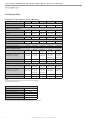
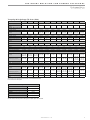
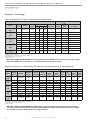
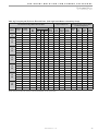
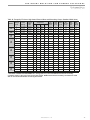
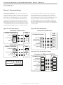
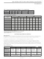
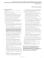
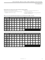
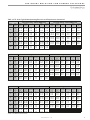
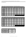
Unit Physical Data
Tranquility
27
®
Two-Stage (TT) Series (60Hz Only)
Model 026 038 049 064 072
Compressor (1 Each) Two-Stage Scroll
Factory Charge (HFC-410A) (oz) [kg] 58 [1.64] 78 [2.21] 81 [2.30] 144 [4.08] 156 [4.42]
ECM Fan Motor & Blower
Fan Motor (hp) [W] 1/2 [373] 1/2 [373] 1 [746] 1 [746] 1 [746]
Blower Wheel Size (dia x w) -
(in) [mm]
9 x 7
[229 x 178]
11 x 10
[279 x 254]
11 x 10
[279 x 254]
11 x 10
[279 x 254]
11 x 10
[279 x 254]
Water Connection Size
FPT (in) 3/4 3/4 1 1 1
HWG Connection Size
FPT (in) 1/2 1/2 1/2 1/2 1/2
Coax Volume
Volume (US Gallons) [liters] 0.76 [2.88] 0.92 [3.48] 1.24 [4.69] 1.56 [5.91] 1.56 [5.91]
Vertical Upow/Downow
Air Coil Dimensions (h x w) - (in) [mm]
28 x 20
[711 x 508]
28 x 25
[711 x 635]
32 x 25
[813 x 635]
36 x 25
[914 x 635]
36 x 25
[914 x 635]
Standard Filter - 1” [25.4mm]
Throwaway, qty (in) [mm]
28 x 24
[711 x 610]
28 x 30
[711 x 762]
2 - 16 x 30
[406 x 762]
1 - 16 x 30
[813 x 762]
1 - 20 x 30
[508 x 762]
1 - 16 x 30
[813 x 762]
1 - 20 x 30
[508 x 762]
Weight - Operating, (lbs) [kg] 266 [121] 327 [148] 416 [189] 443 [201] 443 [201]
Weight - Packaged, (lbs) [kg] 276 [125] 337 [153] 426 [193] 453 [205] 453 [205]
Horizontal
Air Coil Dimensions (h x w) - (in) [mm]
18 x 31
[457 x 787]
20 x 35
[508 x 889]
20 x 40
[508 x 1016]
20 x 45
[508 x 1143]
20 x 45
[508 x 1143]
Standard Filter - 1” [25.4mm]
Throwaway, qty (in) [mm]
2 - 18 x 18
[457 x 457]
1 - 12 x 20
[305 x 508]
1 - 20 x 25
[508 x 635]
1 - 18 x 20
[457 x 508]
1 - 20 x 24
[508 x 610]
2 - 20 x 24
[508 x 610]
2 - 20 x 24
[508 x 610]
Weight - Operating, (lbs) [kg] 266 [121] 327 [148] 416 [189] 443 [201] 443 [201]
Weight - Packaged, (lbs) [kg] 276 [125] 337 [153] 426 [193] 453 [205] 453 [205]
Notes:
All units have TXV expansion device and 1/2” & 3/4” electrical knockouts.
575 volt motors are two speed.
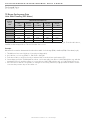
Unit Maximum Water Working Pressure
Options
Max Pressure PSIG [kPa]
Base Unit
500 [3,445]
Internal Secondary Pump (ISP)
145 [999]
ClimaDry
145 [999]
Internal Motorized Water Valve (MWV)
300 [2,067]
Internal Auto Flow Valve
500 [3,445]
Use the lowest maximum pressure rating when multiple options are combined.

T H E S M A R T S O L U T I O N F O R E N E R G Y E F F I C I E N C Y
Packaged Units
R e v. : 0 3 J a n u a r y, 2 0 1 1
7
c l i m a t e m a s t e r. c o m
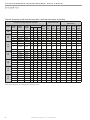
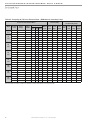
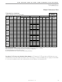
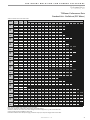
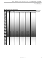
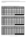
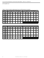
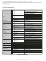
Tranquility 20 Single-Stage (TS) Series (60Hz)
Model 006 009 012 018 024 030 036 042 048 060 070
Compressor (1 Each)
Rotary Scroll
Factory Charge HFC-410A
(oz) [kg]
24 [0.68] 32 [0.91] 34 [0.96] 50 [1.13] 56 [1.59] 58 [1.64] 70 [1.98] 80 [2.27] 80 [2.27] 136 [3.86] 144 [4.08]
ECM Fan Motor & Blower
Fan Motor (hp) [W]
N/A N/A N/A 1/2 [373] 1/2 [373] 1/2 [373] 1/2 [373] 1/2 [373] 1 [746] 1 [746] 1 [746]
Blower Wheel Size (dia x w) -
(in) [mm]
N/A N/A N/A
9 x 7
[229 x 178]
9 x 7
[229 x 178]
9 x 7
[229 x 178]
11 x 10
[279 x 254]
11 x 10
[279 x 254]
11 x 10
[279 x 254]
11 x 10
[279 x 254]
11 x 10
[279 x 254]
PSC Fan Motor & Blower (3 Speeds)
Fan Motor (hp) [W]
1/25 [30] 1/20 [37] 1/8 [93] 1/6 [124] 1/5 [149] 1/3 [249] 1/2 [373] 1/2 [373] 3/4 [560] 1 [746] 1 [746]
High Static Fan Motor (hp) [W]
N/A N/A N/A 1/5 [149] 1/3 [249] 1/2 [373] 1/2 [373] 3/4 [560] 3/4 [560] 1 [746] Not Available
Blower Wheel Size (dia x w) -
(in) [mm]
6 X 5
[152 X 127]
6 X 5
[152 X 127]
6 X 5
[152 X 127]
9 x 7
[229 x 178]
9 x 7
[229 x 178]
9 x 7
[229 x 178]
10 x 10
[254 x 254]
10 x 10
[254 x 254]
10 x 10
[254 x 254]
11 x 10
[279 x 254]
11 x 10
[279 x 254]
Water Connection Size
FPT (in)
1/2” 1/2” 1/2” 3/4” 3/4” 3/4” 3/4” 1” 1” 1” 1”
HWG Connection Size
FPT (in)
N/A N/A N/A 1/2” 1/2” 1/2” 1/2” 1/2” 1/2” 1/2” 1/2”
Coax Volume
Volume (US Gallons) [liters]
0.17 [0.64] 0.29 [1.10] 0.45 [1.70] 0.56 [2.12] 0.76 [2.88] 0.76 [2.88] 0.92 [3.48] 1.24 [4.69] 1.24 [4.69] 1.56 [5.91] 1.56 [5.91]
Vertical Upow/Downow
Air Coil Dimensions (h x w) -
(in) [mm]
16 x 16
[406 x 406]
Upow Only
16 x 16
[406 x 406]
Upow Only
16 x 16
[406 x 406]
Upow Only
24 x 20
[610 x 508]
28 x 20
[711 x 508]
28 x 20
[711 x 508]
28 x 25
[711 x 635]
32 x 25
[813 x 635]
32 x 25
[813 x 635]
36 x 25
[914 x 635]
36 x 25
[914 x 635]
Standard Filter - 1” [25.4mm]
Throwaway, qty (in) [mm]
16 x 20
[406 x 508]
16 x 20
[406 x 508]
16 x 20
[406 x 508]
24 x 24
[610 x 610]
28 x 24
[711 x 610]
28 x 24
[711 x 610]
28 x 30
[711 x 762]
2 - 16 x 30
[2 - 406 x 762]
2 - 16 x 30
[2 - 406 x 762]
1 - 16 x 30;
1 - 20 x 30
[1 - 406 x 762;
1 - 508 x 762]
1 - 16 x 30;
1 - 20 x 30
[1 - 406 x 762;
1 - 508 x 762]
Weight - Operating, (lbs) [kg]
126 [57] 146 [66] 150 [68] 252 [114] 266 [121] 268 [122] 327 [148] 414 [188] 416 [189] 441 [200] 443 [201]
Weight - Packaged, (lbs) [kg]
136 [62] 156 [71] 160 [73] 262 [119] 276 [125] 278 [126] 337 [153] 424 [192] 426 [193] 451 [205] 453 [206]
Horizontal
Air Coil Dimensions (h x w) -
(in) [mm]
16 x 16
[406 x 406]
16 x 16
[406 x 406]
16 x 16
[406 x 406]
18 x 27
[457 x 686]
18 x 31
[457 x 787]
18 x 31
[457 x 787]
20 x 35
[508 x 889]
20 x 40
[508 x 1016]
20 x 40
[508 x 1016]
20 x 45
[508 x 1143]
20 x 45
[508 x 1143]
Standard Filter - 1” [25.4mm]
Throwaway, qty (in) [mm]
16 x 20
[406 x 508]
16 x 20
[406 x 508]
16 x 20
[406 x 508]
2 - 18 x 18
[2 - 457 x 457]
2 - 18 x 18
[2 - 457 x 457]
2 - 18 x 18
[2 - 457 x 457]
1 - 12 x 20;
1- 20 x 25
[1 - 305 x 508;
1 - 508 x 635]
1 - 18 x 20;
1 - 20 x 24
[1 - 457 x 508;
1 - 508 x 610]
1 - 18 x 20;
1 - 20 x 24
[1 - 457 x 508;
1 - 508 x 610]
2 - 20 x 24
[2 - 508 x 610]
2 - 20 x 24
[2 - 508 x 610]
Weight - Operating, (lbs) [kg]
136 [62] 156 [71] 160 [73] 257 [117] 266 [121] 268 [122] 327 [148] 414 [188] 416 [189] 441 [200] 443 [201]
Weight - Packaged, (lbs) [kg]
146 [66] 166 [72] 170 [77] 267 [121] 276 [125] 278 [126] 337 [153] 424 [192] 426 [193] 451 [205] 453 [206]
Notes:
All units have TXV expansion device and 1/2” & 3/4” electrical knockouts.
575 volt motors are two speed.
Unit Maximum Water Working Pressure
Options
Max Pressure PSIG [kPa]
Base Unit
500 [3,445]
Internal Secondary Pump (ISP)
145 [999]
ClimaDry
145 [999]
Internal Motorized Water Valve (MWV)
300 [2,067]
Internal Auto Flow Valve
500 [3,445]
Use the lowest maximum pressure rating when multiple options are combined.

C L I M A T E M A S T E R W A T E R - S O U R C E H E A T P U M P S
Packaged Units
R e v. : 0 3 J a n u a r y, 2 0 1 1
8
C l i m a t e M a s t e r Wa t e r - S o u r c e H e a t P u m p s
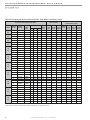
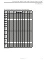
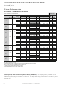
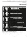
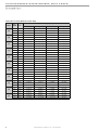
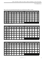
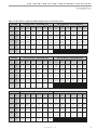
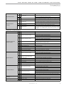
TC Series 006 009 012 015 018 024 030 036 042 048 060
Compressor (1 Each)
Rotary Scroll
Factory Charge HFC-410A (oz)
17 18.5 23 32 43 43 47 50 70 74 82
PSC Fan Motor & Blower
Fan Motor Type/Speeds
PSC/3 PSC/3 PSC-3 PSC/3 PSC/3 PSC/3 PSC/3 PSC/3 PSC/3 PSC/3 PSC/3
Fan Motor (hp)
1/25 1/10 1/10 1/6 1/6 1/4 3/4 1/2 3/4 3/4 1
Blower Wheel Size (Dia x w)
5x5 5x5 6x5 8x7 8x7 9x7 9x7 9x8 9x8 10x10 11x10
Water Connection Size
FPT
1/2” 1/2” 1/2” 1/2" 1/2" 3/4" 3/4" 3/4" 3/4" 1" 1"
Coax Volume (gallons)
0.123 0.143 0.167 0.286 0.450 0.286 0.323 0.323 0.890 0.738 0.939
Vertical
Air Coil Dimensions (H x W)
10x15 10x15 10x15 20x17.25 20x17.25 20x17.25 20x17.25 24x21.75 24x21.76 24x28.25 24x28.25
Filter Standard - 1" Throwaway
10x18 10x18 10x18 20x20 20x20 20x20 20x20 24x24 24x24
1-14x24,
1-18x24
1-14x24,
1-18x24
Weight - Operating (lbs.)
103 105 114 153 158 189 197 203 218 263 278
Weight - Packaged (lbs.)
113 115 124 158 163 194 202 209 224 270
285
Horizontal
Air Coil Dimensions (H x W)
10x15 10x15 10x15 16x22 16x22 16x22 16x22 20x25 20x25 20x35 20x35
Filter Standard - 1" Throwaway
10x18 10x18 10x18 16x25 16x25 18x25
18x25
20x28 or
2-20x14
20x28 or
2-20x14
1-20x24,
1-20x14
1-20x24,
1-20x14
Weight - Operating (lbs.)
103 105 114 153 158 174 182 203 218 263 278
Weight - Packaged (lbs.)
113 115 124 158 163 179 187 209 224 270 285
Notes:
All units have TXV expansion device, and 1/2” & 3/4” electrical knockouts.
FPT = Female Pipe Thread
Condensate Drain Connection is 3/4” FPT.
575 volt fan motors are two speed.
Unit Maximum Water Working Pressure
Max Pressure PSIG [kPa]
Base Unit
500 [3,445]
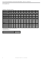
Tranquility 16 (TC) Series (60 Hz)

T H E S M A R T S O L U T I O N F O R E N E R G Y E F F I C I E N C Y
Packaged Units
R e v. : 0 3 J a n u a r y, 2 0 1 1
9
c l i m a t e m a s t e r. c o m
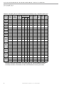
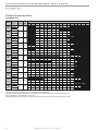
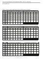
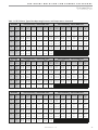
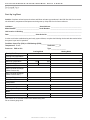
TR Series 006 009 012 015 018 024 030 036 042 048 060
Compressor (1 each)
Rotary Scroll
Factory Charge HFC-410A - (oz.)
17 18.5 23 35 43 43 48 50 70 74 82
PSC Fan Motor & Blower
Fan Motor Type/Speeds
PSC/3 PSC/3 PSC/3 PSC/3 PSC/3 PSC/3 PSC/3 PSC/3 PSC/3 PSC/3 PSC/3
Fan Motor (hp)
1/25 1/10 1/10 1/6 1/6 1/4 3/4 1/2 3/4 3/4 1
Blower Wheel Size (Dia x W)
5x5 5x5 6x5 8x7 8x7 9x7 9x7 9x8 9x8 10x10 11x10
Water Connection Size
Source FPT
1/2” 1/2” 1/2” 1/2” 1/2” 3/4” 3/4” 3/4” 3/4” 1” 1”
Optional HWG FPT
1/2”
Coax Volume (gallons)
0.123 0.143 0.167 0.286 0.45 0.286 0.323 0.323 0.89 0.738 0.939
Vertical
Air Coil Dimensions (H x W)
10x15 10x15 10x15 20x17.25 20x17.25 20x17.25 20x17.25 24x21.75 24x21.76 28x25 28x25
Filter Standard - 1” Throwaway
10x18 10x18 10x18 20x20 20x20 20x20 20x20 24x24 24x24 28x28 28x28
Weight - Operating (lbs.)
110 112 121 163 168 184 192 213 228 283 298
Weight - Packaged (lbs.)
115 117 126 168 173 189 197 219 234 290 305
Horizontal
Air Coil Dimensions (H x W)
10x15 10x15 10x15 16x22 16x22 16x22 16x22 20x25 20x25 20x35 20x35
Filter Standard - 1” Throwaway
10x18 10x18 10x18 16x25 16x25 18x25 18x25 20x28 or 2-20x14 20x28 or 2-20x14 1-20x24, 1-20x14 1-20x24, 1-20x14
Weight - Operating (lbs.)
110 112 121 163 168 184 192 213 228 283 298
Weight - Packaged (lbs.)
115 117 126 168 173 189 197 219 234 290 305
Notes: All units have TXV expansion device and 1/2” & 3/4” electrical knockouts.
575 volt fan motors are two speed.
FPT=Female Pipe Thread
Condensate Drain Connection is 3/4” FPT.
Unit Maximum Water Working Pressure
Options Max Pressure PSIG [kPa]
Base Unit 500 [3,445]
Internal Secondary Pump (ISP)
145 [999]
Internal Motorized Water Valve (MWV)
300 [2,067]
Internal Auto Flow Valve
500 [3,445]
ClimaDry
145 [999]
Use the lowest maximum pressure rating when multiple options are combined.
Tranquility (TR) Series (60 Hz)

C L I M A T E M A S T E R W A T E R - S O U R C E H E A T P U M P S
Packaged Units
R e v. : 0 3 J a n u a r y, 2 0 1 1
10
C l i m a t e M a s t e r Wa t e r - S o u r c e H e a t P u m p s
6.4mm pitch
for drainage
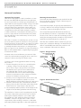
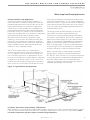
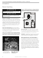
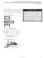
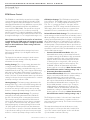
Horizontal Installation
Mounting Horizontal Units
Horizontal units have hanger kits pre-installed from the
factory as shown in Figure 1. Figure 3 shows a typical
horizontal unit installation.
Horizontal heat pumps are typically suspended above
a ceiling or within a soffit using field supplied, threaded
rods sized to support the weight of the unit.
Use four (4) field supplied threaded rods and factory
provided vibration isolators to suspend the unit. Hang
the unit clear of the floor slab above and support the
unit by the mounting bracket assemblies only. DO NOT
attach the unit flush with the floor slab above.
Pitch the unit toward the drain as shown in Figure 2 to
improve the condensate drainage. On small units (less
than 2.5 tons/8.8kW) ensure that unit pitch does not
cause condensate leaks inside the cabinet.
Figure 1: Hanger Bracket
Figure 2: Horizontal Unit Pitch
3/8" [10mm] Threaded
Rod (by others)
Vibration Isolator
(factory supplied)
Washer
(by others)
Double Hex Nuts
(by others)
Varilla Roscada de 3/8"
(fabricada por terceros)
Arandela
(fabricada por terceros)
Tuercas Hexagonales
Dobles (por terceros)
Instale los Tornillos como
se Indica en el Diagrama
La longitud de este tornillo
debe ser de solamente 1/2” para evitar daños
Aislador de Vibraciones
(para codificación por color y
notas de instalación, consulte
las instrucciones de
instalación del soport
e colgador)
Drain Connection
Horizontal Unit Location
Units are not designed for outdoor installation. Locate
the unit in an INDOOR area that allows enough space
for service personnel to perform typical maintenance or
repairs without removing unit from the ceiling. Horizontal
units are typically installed above a false ceiling or in a
ceiling plenum. Never install units in areas subject to
freezing or where humidity levels could cause cabinet
condensation (such as unconditioned spaces subject
to 100% outside air). Consideration should be given to
access for easy removal of the filter and access panels.
Provide sufficient room to make water, electrical, and
duct connection(s).
If the unit is located in a confined space, such as a closet,
provisions must be made for return air to freely enter the
space by means of a louvered door, etc. Any access panel
screws that would be difficult to remove after the unit
is installed should be removed prior to setting the unit.
Refer to Figure 3 for an illustration of a typical installation.
Refer to unit submittal data or engineering design guide
for dimensional data.
In limited side access installations, pre-removal of the
control box side mounting screws will allow control box
removal for future servicing (TC/TR units only).
Conform to the following guidelines when selecting
unit location:
1. Provide a hinged access door in concealed-spline
or plaster ceilings. Provide removable ceiling
tiles in T-bar or lay-in ceilings. Refer to horizontal
unit dimensions for specific series and model in
unit submittal data. Size the access opening to
accommodate the service technician during the
removal or replacement of the compressor and the
removal or installation of the unit itself.
2. Provide access to hanger brackets, water valves and
fittings. Provide screwdriver clearance to access
panels, discharge collars and all electrical connections.
3. DO NOT obstruct the space beneath the unit with
piping, electrical cables and other items that prohibit
future removal of components or the unit itself.
4. Use a manual portable jack/lift to lift and support the
weight of the unit during installation and servicing.
The installation of water source heat pump units and all
associated components, parts and accessories which
make up the installation shall be in accordance with
the regulations of ALL authorities having jurisdiction
and MUST conform to all applicable codes. It is the
responsibility of the installing contractor to determine
and comply with ALL applicable codes and regulations.

T H E S M A R T S O L U T I O N F O R E N E R G Y E F F I C I E N C Y
Packaged Units
R e v. : 0 3 J a n u a r y, 2 0 1 1
11
c l i m a t e m a s t e r. c o m
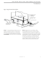
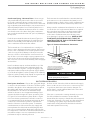
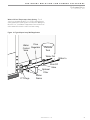
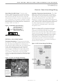
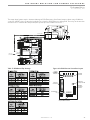
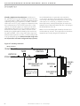
Figure 3: Typical Horizontal Unit Installation
Air Coil - To obtain maximum performance, the air coil
should be cleaned before start-up. A 10% solution of
dishwasher detergent and water is recommended for
both sides of the coil. A thorough water rinse should
follow. UV based anti-bacterial systems may damage
coated air coils.
Notice! Installation Note - Ducted Return: Many
horizontal WSHPs are installed in a return air ceiling
plenum application (above ceiling). Vertical WSHPs are
commonly installed in a mechanical room with free return
(e.g. louvered door). Therefore, filter rails are the industry
standard and are included on ClimateMaster commercial
heat pumps for the purposes of holding the filter only.
For ducted return applications, the filter rail must be
removed and replaced with a duct flange or filter rack.
Canvas or flexible connectors should also be used to
minimize vibration between the unit and ductwork.
HORIZONTAL INSTALLATION
(by others)
(by others)
Cableado
del termostato
Válvula compensadora opcional
Salida de agua
Entrada de agua
Válvula invertida opcional para
control de baja presión de agua
(puede montarse en forma interna)
Válvula a bola con tapón
P/T integrado opcional
Manguera trenzada de
acero inoxidable con accesorio
giratorio en “J”
Circuito
de edificación
Disyuntor de
energía de la unidad
(fabricado por terceros)
Alimentación
de energía de
la unidad
Conducto de alimentación
aislado con un codo (mínimo)
de 90 grados para reducir el
ruido del aire
Retorno de
aire
Aire de alimentación
Cableado de
alimentación
de energía
Varillas Roscadas de 3/8"
(fabricadas por terceros)
Colgador
de la unidad
Thermostat
Wiring
Water In
Water Out
Optional Balancing Valve
Ball Valve with optional
integral P/T plug
Stainless steel braid hose
with integral "J" swivel
Building
Loop
Unit Power
Disconnect
Power Wiring
Insulated supply duct with
at least one 90 deg elbow
to reduce air noise
Return Air
Supply Air
Unit Hanger
3/8" [10mm] threaded rods
Unit Power
Flexible Duct
Connector
Figure 3: Typical Horizontal Unit Installation
Optional Low Pressure Drop Water
Control Valve
(can be internally mounted
on some models)

C L I M A T E M A S T E R W A T E R - S O U R C E H E A T P U M P S
Packaged Units
R e v. : 0 3 J a n u a r y, 2 0 1 1
12
C l i m a t e M a s t e r Wa t e r - S o u r c e H e a t P u m p s
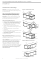
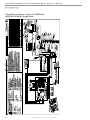
Field Conversion of Air Discharge
Water
Connection End
Return Air
Remove Screws
Water
Connection End
Return Air
Rotate
Move to Side
Side Discharge
Return Air
Water
Connection End
Discharge Air
Drain
Back Discharge
Replace Screws
Extremo de Con
Conducto de Alimentación
Retorno de Aire
Extremo de Conexión de Agua
Drenaje
Retorno de Aire
Descarga de Aire
Descarga Lateral
Descarga Posterior
Water
Connection End
Supply Duct
Return Air
Water
Connection End
Drain
Return Air
Discharge Air
Side Discharge
Back Discharge
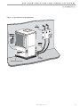
Overview - Horizontal units can be field converted
between side (straight) and back (end) discharge using
the instructions below.
Note: It is not possible to field convert return air
between left or right return models due to the
necessity of refrigeration copper piping changes.
Preparation - It is best to field convert the unit on the
ground before hanging. If the unit is already hung it
should be taken down for the field conversion.
Side to Back Discharge Conversion
1. Place unit in well lit area. Remove the screws as shown
in Figure 4 to free top panel and discharge panel.
2. Lift out the access panel and set aside. Lift and rotate
the discharge panel to the other position as shown,
being careful with the blower wiring.
3. Check blower wire routing and connections for
tension or contact with sheet metal edges. Re-route if
necessary.
4. Check refrigerant tubing for contact with other
components.
5. Reinstall top panel and screws noting that the location
for some screws will have changed.
6. Manually spin the fan wheel to ensure that the wheel
is not rubbing or obstructed.
7. Replace access panels.
Back to Side Discharge Conversion - If the discharge is
changed from back to side, use above instruction noting
that illustrations will be reversed.
Left vs. Right Return - It is not possible to field convert
return air between left or right return models due to
the necessity of refrigeration copper piping changes.
However, the conversion process of side to back or
back to side discharge for either right or left return
configuration is the same. In some cases, it may be
possible to rotate the entire unit 180 degrees if the return
air connection needs to be on the opposite side. Note
that rotating the unit will move the piping to the
other end of the unit.
Figure 5: Right Return Side to Back
Figure 4: Left Return Side to Back

T H E S M A R T S O L U T I O N F O R E N E R G Y E F F I C I E N C Y
Packaged Units
R e v. : 0 3 J a n u a r y, 2 0 1 1
13
c l i m a t e m a s t e r. c o m
Each unit must be installed with its own individual trap
and connection to the condensate line (main) or riser.
Provide a means to flush or blow out the condensate line.
DO NOT install units with a common trap and/or vent.
Always vent the condensate line when dirt or air can col-
lect in the line or a long horizontal drain line is required.
Also vent when large units are working against higher
external static pressure than other units connected
to the same condensate main since this may cause
poor drainage for all units on the line. WHEN A VENT
IS INSTALLED IN THE DRAIN LINE, IT MUST BE
LOCATED AFTER THE TRAP IN THE DIRECTION OF
THE CONDENSATE FLOW.
*3/4" FPT
Trap Depth
1.5" [38mm]
Min 1.5"
[38mm]
1/4" per foot
(21mm per m)
drain slope
3/4" PVC or
Copper by others
Rev.: 4/30/10B
Vent
* Some units include a painted drain
connection. Using a threaded pipe or
similar device to clear any excess paint
accumulated inside this fitting may
ease final drain line installation.
Figure 6: Horizontal Condensate Connection
CAUTION! Ensure condensate line is pitched toward drain
1/4 inch per ft [21mm per m] of run.
CAUTION!
Duct System Installation - Proper duct sizing and design
is critical to the performance of the unit. The duct system
should be designed to allow adequate and even airflow
through the unit during operation. Air flow through
the unit MUST be at or above the minimum stated
airflow for the unit to avoid equipment damage. Duct
systems should be designed for quiet operation. Refer
to Figure 3 for horizontal duct system details or Figure
8 for vertical duct system details. A flexible connector
is recommended for both discharge and return air duct
connections on metal duct systems to eliminate the
transfer of vibration to the duct system. To maximize
sound attenuation of the unit blower, the supply and
return plenums should include internal fiberglass duct
liner or be constructed from ductboard for the first few
feet. Application of the unit to uninsulated ductwork in an
unconditioned space is not recommended, as the unit’s
performance may be adversely affected.
DUCT SYSTEM INSTALLATION
Condensate Piping
Duct System Installation
Condensate Piping - Horizontal Units - Units are typi-
cally installed directly above each other on successive
floors with condensate drains located near the units.
Attach the unit condensate drain connection to the build-
ing condensate drain with a flexible, non-pressure-rated
3/4 inch [19mm] ID plastic hose. Ensure that the hose is
without kinks to maintain unobstructed flow of conden-
sate from the unit to the drain. Verify that condensate
line is pitched towards the drain 1/4” per foot (10mm per
46cm) of run.
Pitch the unit toward the drain as shown in Figure 2 to
improve the condensate drainage. On small units (less
than 2.5 tons/8.8 kW), ensure that unit pitch does not
cause condensate leaks inside the cabinet.
The horizontal run of a condensate hose is usually too
short to cause drainage problems. However, the horizon-
tal run of the condensate line should be pitched at least
1 inch for every 10 feet [10mm per 116cm] of run in the
direction of flow to ensure that the connection will not
slip off due to excessive weight or piping expansion/con-
traction. Avoid low points and non-pitched piping since
dirt collects in low or level areas and may cause stoppage
and overflow.
Install condensate trap at each unit with the top of the
trap positioned below the unit condensate drain con-
nection as shown in Figure 6. Design the depth of the
trap (water-seal) based upon the amount of ESP capabil-
ity of the blower (where 2 inches [51mm] of ESP capability
requires 2 inches [51mm] of trap depth). As a general rule,
1-1/2 inch [38mm] trap depth is the minimum.
At least one 90° elbow should be included in the supply
duct to reduce air noise. If air noise or excessive air flow
is a problem, the blower speed can be changed. For
airflow charts, consult submittal data for the series and
model of the specific unit.
If the unit is connected to existing ductwork, a previous
check should have been made to ensure that the
ductwork has the capacity to handle the airflow required
for the unit. If ducting is too small, as in the replacement
of a heating only system, larger ductwork should be
installed. All existing ductwork should be checked for
leaks and repaired as necessary.

C L I M A T E M A S T E R W A T E R - S O U R C E H E A T P U M P S
Packaged Units
R e v. : 0 3 J a n u a r y, 2 0 1 1
14
C l i m a t e M a s t e r Wa t e r - S o u r c e H e a t P u m p s
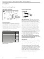
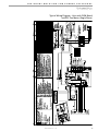
Vertical Installation
Flexible canvas duct
connector to reduce
noise and vibration
Use turning vanes in
supply transition
Internally insulate supply
duct for first 1.2 m each way
to reduce noise
Internally insulate return
transition duct to reduce
noise
Rounded return
transition
Flexible canvas duct
connector to reduce
noise and vibration
Use turning vanes in
supply transition
Internally insulate supply
duct for first 4’ [1.2m] each
way to reduce noise
Internally insulate return
transition duct to reduce
noise
Rounded return
transition
Rev.: 6/2/09S
Rev.: 6/2/09S
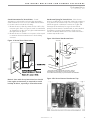
Figure 7: Vertical Unit Mounting
Figure 8: Typical Vertical Unit Installation Using
Ducted Return Air
bloque o del ladrillo o sacado
Cojín del aire o sacado
Bloque o ladrillo concreto
Air Pad or extruded
polystyrene insulation board
Vertical Unit Location - Units are not designed for
outdoor installation. Locate the unit in an INDOOR
area that allows enough space for service personnel to
perform typical maintenance or repairs without removing
unit from the mechanical room/closet. Vertical units
are typically installed in a mechanical room or closet.
Never install units in areas subject to freezing or where
humidity levels could cause cabinet condensation (such
as unconditioned spaces subject to 100% outside air).
Consideration should be given to access for easy removal
of the filter and access panels. Provide sufficient room to
make water, electrical, and duct connection(s).
If the unit is located in a confined space, such as a closet,
provisions must be made for return air to freely enter
the space by means of a louvered door, etc. Any access
panel screws that would be difficult to remove after
the unit is installed should be removed prior to setting
the unit. Refer to Figures 7 and 8 for typical installation
illustrations. Refer to unit submittal data or engineering
design guide for dimensional data.
1. Install the unit on a piece of rubber, neoprene or
other mounting pad material for sound isolation. The
pad should be at least 3/8” [10mm] to 1/2” [13mm] in
thickness. Extend the pad beyond all four edges of
the unit.
2. Provide adequate clearance for filter replacement
and drain pan cleaning. Do not block filter access
with piping, conduit or other materials. Refer to
unit submittal data or engineering design guide for
dimensional data.
3. Provide access for fan and fan motor maintenance
and for servicing the compressor and coils without
removing the unit.
4. Provide an unobstructed path to the unit within the
closet or mechanical room. Space should be sufficient
to allow removal of the unit, if necessary.
5. In limited side access installations, pre-removal of the
control box side mounting screws will allow control
box removal for future servicing (TC/TR units only).
6. Provide access to water valves and fittings and
screwdriver access to the unit side panels, discharge
collar and all electrical connections.
Vertical Unit Location

T H E S M A R T S O L U T I O N F O R E N E R G Y E F F I C I E N C Y
Packaged Units
R e v. : 0 3 J a n u a r y, 2 0 1 1
15
c l i m a t e m a s t e r. c o m
Sound Attenuation for Vertical Units - Sound
attenuation is achieved by enclosing the unit within a
small mechanical room or a closet. Additional measures
for sound control include the following:
1. Mount the unit so that the return air inlet is 90° to the
return air grille. Refer to Figure 9. Install a sound baffle
as illustrated to reduce line-of sight sound transmitted
through return air grilles.
2. Mount the unit on a rubber or neoprene isolation pad
to minimize vibration transmission to the building
structure.
Figure 9: Vertical Sound Attenuation
Condensate Piping for Vertical Units - Vertical units
utilize a condensate hose inside the cabinet as a trapping
loop; therefore an external trap is not necessary. Figure
10a shows typical condensate connections. Figure 10b
illustrates the internal trap for a typical vertical heat
pump. Each unit must be installed with its own individual
vent (where necessary) and a means to flush or blow
out the condensate drain line. Do not install units with a
common trap and/or vent.
Vent
*3/4" FPT
3/4" PVC
Alternate
Condensate
Location
Water
Connections
(21mm per m)
* Some units include a painted drain connection. Using a
threaded pipe or similar device to clear any excess paint
accumulated inside this fitting may ease final drain line installation.
Figure 10a: Vertical Condensate Drain
Figure 10b: Vertical Internal Condensate Trap
Notice! Units with clear plastic drain lines should
have regular maintenance (as required) to avoid
buildup of debris, especially in new construction.

C L I M A T E M A S T E R W A T E R - S O U R C E H E A T P U M P S
Packaged Units
R e v. : 0 3 J a n u a r y, 2 0 1 1
16
C l i m a t e M a s t e r Wa t e r - S o u r c e H e a t P u m p s
Piping Installation
CAUTION! Corrosive system water requires corrosion
resistant ttings and hoses, and may require water treatment.
Table 1: Metal Hose Minimum Bend Radii
Hose Diameter Minimum Bend Radii
1/2" [12.7mm] 2-1/2" [6.4cm]
3/4" [19.1mm] 4" [10.2cm]
1" [25.4mm] 5-1/2" [14cm]
1-1/4" [31.8mm] 6-3/4" [17.1cm]
CAUTION! Do not bend or kink supply lines or hoses.
NOTICE! Do not allow hoses to rest against structural
building components. Compressor vibration may
be transmitted through the hoses to the structure,
causing unnecessary noise complaints.
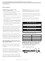
Figure 11: Supply/Return Hose Kit
CAUTION!
CAUTION!
CAUTION!
Rib Crimped
Length
(2 ft [0.6m] Length Standard)
Swivel
Brass
Fitting
Brass
Fitting
MPT
Reborde Acanalado
Longitud
(Long. Estándar de 2 pies)
Accesorio
Giratorio
de Bronce
Accesorio
de Bronce
MPT
CAUTION! Piping must comply with all applicable codes.
Installation of Supply and Return Piping
Follow these piping guidelines.
1. Install a drain valve at the base of each supply and
return riser to facilitate system flushing.
2. Install shut-off / balancing valves and unions at each
unit to permit unit removal for servicing.
3. Place strainers at the inlet of each system circulating
pump.
4. Select the proper hose length to allow slack between
connection points. Hoses may vary in length by +2%
to -4% under pressure.
5. Refer to Table 1. Do not exceed the minimum bend
radius for the hose selected. Exceeding the minimum
bend radius may cause the hose to collapse, which
reduces water flow rate. Install an angle adapter to
avoid sharp bends in the hose when the radius falls
below the required minimum.
Insulation is not required on loop water piping except
where the piping runs through unheated areas, outside
the building or when the loop water temperature is
below the minimum expected dew point of the pipe
ambient conditions. Insulation is required if loop water
temperature drops below the dew point (insulation is
required for ground loop applications in most climates).
Pipe joint compound is not necessary when Teflon
®
thread tape is pre-applied to hose assemblies or when
flared-end connections are used. If pipe joint compound
is preferred, use compound only in small amounts on
the external pipe threads of the fitting adapters. Prevent
sealant from reaching the flared surfaces of the joint.
Note: When antifreeze is used in the loop, ensure
that it is compatible with the Teflon tape or pipe joint
compound that is applied.
Maximum allowable torque for brass fittings is 30 ft-lbs
[41 N-m]. If a torque wrench is not available, tighten
finger-tight plus one quarter turn. Tighten steel fittings
as necessary.
Optional pressure-rated hose assemblies designed
specifically for use with ClimateMaster units are available.
Similar hoses can be obtained from alternate suppliers.
Supply and return hoses are fitted with swivel-joint fittings
at one end to prevent kinking during installation.
Refer to Figure 11 for an illustration of a typical supply/
return hose kit. Adapters secure hose assemblies to the
unit and risers. Install hose assemblies properly and check
regularly to avoid system failure and reduced service life.
Installer Caution: After making water connections on
units equipped with ClimaDry, ensure the three union
nuts on the internal three-way water valve are tight.
ClimaDry-equipped units have a manual air bleed valve
at the top of the reheat coil. This valve must be used to
bleed the air from the reheat coil after filling the system,
for the ClimaDry to operate properly.
A backup wrench is required when tightening water
connections on TC Series units to prevent water line
damage.

T H E S M A R T S O L U T I O N F O R E N E R G Y E F F I C I E N C Y
Packaged Units
R e v. : 0 3 J a n u a r y, 2 0 1 1
17
c l i m a t e m a s t e r. c o m
Water-Loop Heat Pump Applications
Commercial Water Loop Applications
Commercial systems typically include a number of
units connected to a common piping system. Any unit
plumbing maintenance work can introduce air into the
piping system; therefore air elimination equipment is
a major portion of the mechanical room plumbing. In
piping systems expected to utilize water temperatures
below 50°F [10°C], 1/2” [13mm] closed cell insulation is
required on all piping surfaces to eliminate condensation
(extended range units required). Metal to plastic
threaded joints should never be used due to their
tendency to leak over time. All commercial class units
(except TC series) include low temperature-soldered
bracket-supported FPT water connections, which do not
require a backup wrench. A backup wrench must be
used for TC series equipment fittings.
Teflon
®
tape thread sealant is recommended to
minimize internal fouling of the heat exchanger. Do
not over tighten connections and route piping so as
not to interfere with service or maintenance access.
Hose kits are available from ClimateMaster in different
configurations as shown in Figure 12 for connection
between the unit and the piping system. Depending
upon selection, hose kits may include shut off valves,
P/T plugs for performance measurement, high pressure
stainless steel braided hose, “Y” type strainer with blow
down valve, and/or “J” type swivel connection. Balancing
valves and an external low pressure drop solenoid valve
for use in variable speed pumping systems may also be
included in the hose kit.
The piping system should be flushed to remove dirt,
piping chips, and other foreign material prior to
operation (see “Piping System Cleaning and Flushing
Procedures” in this manual). The flow rate is usually set
between 2.25 and 3.5 gpm per ton [2.9 and 4.5 l/m per
kW] of cooling capacity. ClimateMaster recommends 3
gpm per ton [3.9 l/m per kW] for most applications of
water loop heat pumps. To ensure proper maintenance
and servicing, P/T ports are imperative for temperature
and flow verification, as well as performance checks.
Water loop heat pump (cooling tower/boiler) systems
typically utilize a common loop, maintained between
60 - 90°F [16 - 32°C]. The use of a closed circuit evaporative
cooling tower with a secondary heat exchanger between
the tower and the water loop is recommended. If an
open type cooling tower is used continuously, chemical
treatment and filtering will be necessary.
Figure 12: Typical Water-Loop Application
3/8" [10mm] threaded rods
(by others)
Low Water Temperature Cutout Setting - CXM Control
When antifreeze is selected, the FP1 jumper (JW3) should be clipped to select the low temperature (antifreeze 10.0°F
[-12.2°C]) setpoint and avoid nuisance faults (see “Low Water Temperature Cutout Selection” in this manual). Note:
Low water temperature operation requires extended range equipment.

C L I M A T E M A S T E R W A T E R - S O U R C E H E A T P U M P S
Packaged Units
R e v. : 0 3 J a n u a r y, 2 0 1 1
18
C l i m a t e M a s t e r Wa t e r - S o u r c e H e a t P u m p s
Ground-Loop Heat Pump Applications
Pre-Installation
Prior to installation, locate and mark all existing
underground utilities, piping, etc. Install loops for new
construction before sidewalks, patios, driveways, and other
construction has begun. During construction, accurately
mark all ground loop piping on the plot plan as an aid in
avoiding potential future damage to the installation.
Piping Installation
The typical closed loop ground source system is shown in
Figure 13. All earth loop piping materials should be limited
to polyethylene fusion only for in-ground sections of the
loop. Galvanized or steel fittings should not be used at any
time due to their tendency to corrode. All plastic to metal
threaded fittings should be avoided due to their potential
to leak in earth coupled applications. A flanged fitting
should be substituted. P/T plugs should be used so that
flow can be measured using the pressure drop of the unit
heat exchanger.
Earth loop temperatures can range between 25 and 110°F
[-4 to 43°C]. Flow rates between 2.25 and 3 gpm [2.41 to
3.23 l/m per kW] of cooling capacity is recommended in
these applications.
Test individual horizontal loop circuits before backfilling.
Test vertical U-bends and pond loop assemblies prior to
installation. Pressures of at least 100 psi [689 kPa] should
be used when testing. Do not exceed the pipe pressure
rating. Test entire system when all loops are assembled.
Flushing the Earth Loop
Upon completion of system installation and testing, flush
the system to remove all foreign objects and purge to
remove all air.
Antifreeze
I
n areas where minimum entering loop temperatures
drop below 40°F [5°C] or where piping will be routed
through areas subject to freezing, antifreeze is required.
Alcohols and glycols are commonly used as antifreeze;
however your local sales office should be consulted to
determine the antifreeze best suited to your area. Freeze
protection should be maintained to 15°F [9°C] below
the lowest expected entering loop temperature. For
example, if 30°F [-1°C] is the minimum expected entering
loop temperature, the leaving loop temperature would
be 22 to 25°F [-6 to -4°C] and freeze protection should be
at 15°F [-10°C]. Calculation is as follows:
30°F - 15°F = 15°F [-1°C - 9°C = -10°C].
All alcohols should be premixed and pumped from
a reservoir outside of the building when possible or
introduced under the water level to prevent fumes.
Calculate the total volume of fluid in the piping system.
Then use the percentage by volume shown in table
2 for the amount of antifreeze needed. Antifreeze
concentration should be checked from a well mixed
sample using a hydrometer to measure specific gravity.
CAUTION! The following instructions represent industry
accepted installation practices for closed loop earth coupled
heat pump systems. Instructions are provided to assist the
contractor in installing trouble free ground loops. These
instructions are recommendations only. State/provincial
and local codes MUST be followed and installation MUST
conform to ALL applicable codes. It is the responsibility of
the installing contractor to determine and comply with ALL
applicable codes and regulations.
Table 2: Antifreeze Percentages by Volume
Low Water Temperature Cutout Setting - CXM Control
When antifreeze is selected, the FP1 jumper (JW3) should
be clipped to select the low temperature (antifreeze
10.0°F [-12.2°C]) setpoint and avoid nuisance faults
(see “Low Water Temperature Cutout Selection” in this
manual). Note: Low water temperature operation
requires extended range equipment.
CAUTION!
CAUTION!
Type
Minimum Temperature for Low Temperature Protection
10°F [-12.2°C] 15°F [-9.4°C] 20°F [-6.7°C] 25°F [-3.9°C]
Methanol
100% USP food grade Propylene Glycol
Ethanol*
25%
38%
29%
21%
25%
25%
16%
22%
20%
10%
15%
14%
* Must not be denatured with any petroleum based product
CAUTION! Ground loop applications require extended range
equipment and optional refrigerant/water circuit insulation.

T H E S M A R T S O L U T I O N F O R E N E R G Y E F F I C I E N C Y
Packaged Units
R e v. : 0 3 J a n u a r y, 2 0 1 1
19
c l i m a t e m a s t e r. c o m
Figure 13: Typical Ground-Loop Application
Vibration Isolation Pad

C L I M A T E M A S T E R W A T E R - S O U R C E H E A T P U M P S
Packaged Units
R e v. : 0 3 J a n u a r y, 2 0 1 1
20
C l i m a t e M a s t e r Wa t e r - S o u r c e H e a t P u m p s
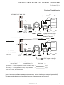
Ground-Water Heat Pump Applications
Open Loop - Ground Water Systems - Typical open
loop piping is shown in Figure 14. Shut off valves should
be included for ease of servicing. Boiler drains or other
valves should be “tee’d” into the lines to allow acid
flushing of the heat exchanger. Shut off valves should be
positioned to allow flow through the coax via the boiler
drains without allowing flow into the piping system. P/T
plugs should be used so that pressure drop and temper-
ature can be measured. Piping materials should be lim-
ited to copper or PVC SCH80.
Note: Due to the pressure and temperature
extremes, PVC SCH40 is not recommended.
Water quantity should be plentiful and of good quality.
Consult table 3 for water quality guidelines. The unit can
be ordered with either a copper or cupro-nickel water
heat exchanger. Consult Table 3 for recommendations.
Copper is recommended for closed loop systems and
open loop ground water systems that are not high in
mineral content or corrosiveness. In conditions anticipat-
ing heavy scale formation or in brackish water, a cupro-
nickel heat exchanger is recommended. In ground water
situations where scaling could be heavy or where bio-
logical growth such as iron bacteria will be present, an
open loop system is not recommended. Heat exchanger
coils may over time lose heat exchange capabilities due
to build up of mineral deposits. Heat exchangers must
only be serviced by a qualified technician, as acid and
special pumping equipment is required. Desuperheater
coils can likewise become scaled and possibly plugged.
In areas with extremely hard water, the owner should
be informed that the heat exchanger may require occa-
sional acid flushing. In some cases, the desuperheater
option should not be recommended due to hard water
conditions and additional maintenance required.
Water Quality Standards - Table 3 should be consulted
for water quality requirements. Scaling potential should
be assessed using the pH/Calcium hardness method. If
the pH <7.5 and the calcium hardness is less than 100
ppm, scaling potential is low. If this method yields num-
bers out of range of those listed, the Ryznar Stability
and Langelier Saturation indecies should be calculated.
Use the appropriate scaling surface temperature for the
application, 150°F [66°C] for direct use (well water/open
loop) and DHW (desuperheater); 90°F [32°F] for indirect
use. A monitoring plan should be implemented in these
probable scaling situations. Other water quality issues
such as iron fouling, corrosion prevention and erosion
and clogging should be referenced in Table 3.
Expansion Tank and Pump - Use a closed, bladder-
type expansion tank to minimize mineral formation due
to air exposure. The expansion tank should be sized to
provide at least one minute continuous run time of the
pump using its drawdown capacity rating to prevent
pump short cycling. Discharge water from the unit is not
contaminated in any manner and can be disposed of in
various ways, depending on local building codes (e.g.
recharge well, storm sewer, drain field, adjacent stream
or pond, etc.). Most local codes forbid the use of sani-
tary sewer for disposal. Consult your local building and
zoning department to assure compliance in your area.
Water Control Valve - Note the placement of the water
control valve in Figure 14. Always maintain water pres-
sure in the heat exchanger by placing the water control
valve(s) on the discharge line to prevent mineral pre-
cipitation during the off-cycle. Pilot operated slow clos-
ing valves are recommended to reduce water hammer.
If water hammer persists, a mini-expansion tank can be
mounted on the piping to help absorb the excess ham-
mer shock. Ensure that the total ‘VA’ draw of the valve
can be supplied by the unit transformer. For instance, a
slow closing valve can draw up to 35VA. This can over-
load smaller 40 or 50 VA transformers depending on
the other controls in the circuit. A typical pilot operated
solenoid valve draws approximately 15VA (see Figure
21). Note the special wiring diagrams for slow closing
valves (Figures 22 & 23).
Flow Regulation - Flow regulation can be accomplished
by two methods. One method of flow regulation involves
simply adjusting the ball valve or water control valve on
the discharge line. Measure the pressure drop through
the unit heat exchanger, and determine flow rate from
Tables 8a through 8e. Since the pressure is constantly
varying, two pressure gauges may be needed. Adjust the
valve until the desired flow of 1.5 to 2 gpm per ton [2.0
to 2.6 l/m per kW] is achieved. A second method of flow
control requires a flow control device mounted on the
outlet of the water control valve. The device is typically
a brass fitting with an orifice of rubber or plastic material
that is designed to allow a specified flow rate. On occa-
sion, flow control devices may produce velocity noise
that can be reduced by applying some back pressure
from the ball valve located on the discharge line. Slightly
closing the valve will spread the pressure drop over both
devices, lessening the velocity noise.
Note: When EWT is below 50°F [10°C], 2 gpm per ton
(2.6 l/m per kW) is required.
Open Loop - Ground Water Systems
Page is loading ...
Page is loading ...
Page is loading ...
Page is loading ...
Page is loading ...
Page is loading ...
Page is loading ...
Page is loading ...
Page is loading ...
Page is loading ...
Page is loading ...
Page is loading ...
Page is loading ...
Page is loading ...
Page is loading ...
Page is loading ...
Page is loading ...
Page is loading ...
Page is loading ...
Page is loading ...
Page is loading ...
Page is loading ...
Page is loading ...
Page is loading ...
Page is loading ...
Page is loading ...
Page is loading ...
Page is loading ...
Page is loading ...
Page is loading ...
Page is loading ...
Page is loading ...
Page is loading ...
Page is loading ...
Page is loading ...
Page is loading ...
Page is loading ...
Page is loading ...
Page is loading ...
Page is loading ...
Page is loading ...
Page is loading ...
Page is loading ...
Page is loading ...
Page is loading ...
Page is loading ...
Page is loading ...
Page is loading ...
Page is loading ...
Page is loading ...
Page is loading ...
Page is loading ...
Page is loading ...
Page is loading ...
Page is loading ...
Page is loading ...
Page is loading ...
Page is loading ...
Page is loading ...
Page is loading ...
Page is loading ...
Page is loading ...
Page is loading ...
Page is loading ...
-
 1
1
-
 2
2
-
 3
3
-
 4
4
-
 5
5
-
 6
6
-
 7
7
-
 8
8
-
 9
9
-
 10
10
-
 11
11
-
 12
12
-
 13
13
-
 14
14
-
 15
15
-
 16
16
-
 17
17
-
 18
18
-
 19
19
-
 20
20
-
 21
21
-
 22
22
-
 23
23
-
 24
24
-
 25
25
-
 26
26
-
 27
27
-
 28
28
-
 29
29
-
 30
30
-
 31
31
-
 32
32
-
 33
33
-
 34
34
-
 35
35
-
 36
36
-
 37
37
-
 38
38
-
 39
39
-
 40
40
-
 41
41
-
 42
42
-
 43
43
-
 44
44
-
 45
45
-
 46
46
-
 47
47
-
 48
48
-
 49
49
-
 50
50
-
 51
51
-
 52
52
-
 53
53
-
 54
54
-
 55
55
-
 56
56
-
 57
57
-
 58
58
-
 59
59
-
 60
60
-
 61
61
-
 62
62
-
 63
63
-
 64
64
-
 65
65
-
 66
66
-
 67
67
-
 68
68
-
 69
69
-
 70
70
-
 71
71
-
 72
72
-
 73
73
-
 74
74
-
 75
75
-
 76
76
-
 77
77
-
 78
78
-
 79
79
-
 80
80
-
 81
81
-
 82
82
-
 83
83
-
 84
84


ClimateMaster TT, TS, TC, TR Install Manual
- Category
- Heat pumps
- Type
- Install Manual
Ask a question and I''ll find the answer in the document
Finding information in a document is now easier with AI
Related papers
-
ClimateMaster ATM11H03 Install Manual
-
-
Carrier 50HS024-060 Unit installation
-
Climate Master TCV009AGC30CRTS Installation guide
-
ClimateMaster Horizontal/Vertical WSHP Datasheet
-
-
-
-
-
Other documents
-
Danfoss EVRF 3-W, NO - 032R9511 Installation guide
-
 Heat Controller HP048 Installation, Operation & Maintenance Manual
-
Greenheck 913836 Remote Condensing Unit Operating instructions
-
Bosch Thermotechnology 7735049132 Installation guide
-
Toshiba Tranquility 20 User manual
-
Heat Controller HBH048 Installation, Operation & Maintenance Manual
-
-
Heat Controller HEV042 Installation, Operation & Maintenance Manual
-
 Heat Controller HEV/H User manual
-
A.O. Smith Conventional System Piping Technical Documents

