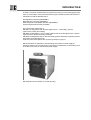
elco Alpha Jetstream MK Installation guide
- Type
- Installation guide

L MK
Assembly, Operating and Maintenance Instructions
Installation
and
User Guide
MK Jetstream
Cast Iron Boiler
320 - 1017 kW
35 Nobel Square Basildon Essex SS13 1LT
01268 591010 / 01268 724064
01/10/05

INTRODUCTION
The MK is a cast iron sectional boiler for pressure jet oil firing or forced draught gas firing
which is constructed in three pass horizontal flue gas circulation principle. MK series are
CE Marked on PIN CE-0645 BO118 to
Gas Appliances Directive (90/396/EEC)
Boiler Efficiency Directive (92/42/EEC)
Electromagnetic Compatability Directive (89/336/EEC)
Pressure Equipment Directive (97/23/EC)
and conforms the requiremets of
EN 303/1: Heating boilers with forced draught burners - Terminology, general
requirements, testing and marking
EN 303/2: Heating boilers - Part 2: Heating boilers with forced draught burners - Special
requirements for boilers atomizing oil burners
EN 303/3: Heating boilers-Part 3: Gas fired heating boilers-Assembly comprising a boiler
body and a forced draught burner
TRD 702: Steam boiler plants with hot water generators of group II
MK series boilers are suitable for central heating and indirect hot water supply at
working pressures not exceeding 6 bars, and working temperatures not exceeding 120 C.
The boiler must never be used for direct water supply.
MK Jetstream Cast Iron Boiler for oil and gas firing

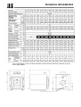
TECHNICAL INFORMATION
(1): In series MK 8-12, flue connection diameter could be reduced minimum to 250 mm by using
a flue spigot adaptor.
Filling/draining tapping size 3/4"
35.0
44.038.0 49.0
55.0
56.0
57.0 60.0 66.0
192 180 178 175 173 170 185 190 195 200

TECHNICAL INFORMATION
Jetstream Jetstream is a PATENTED NEW TECHNOLOGY developed particularly to prevent flue
Technology gas condensation in the boiler. It is based on increasing the temperature of cold return
water to boiler, mixing it with hot circulating water inside boiler. This is accomplished
by a jet effect created by a distribution pipe fixed to the return connection of the boiler.
The cold return water is injected into boiler via a distribution pipe. This injection results
in a pressure drop at the end of the pipe, creating a vacuum. This vacuum sucks hot
delivery water of rear section/sections down to the cold water side, and a mixture of
cold and hot water makes the cold water temperature increase. Thus, the main reason
of flue gas condensation in the boiler is eliminated. A reverse flow of hot delivery water
in the rear section of the boiler protects the section against excessive thermal shocks.
MK Jetstream is operated in non-
condensing mode if the lowest return
water temperatures to boiler given
in the following table are maintained
at thermal equilibrium at nominal
heat output:
Fuels Lowest return temperatures
(
o
C)
Natural gas, LPG 40
Diesel-oil, Fuel-oil 30

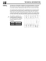
TECHNICAL INFORMATION
Gas resistance
inside the boiler
Efficiencies
Values given according to average boiler water temperature of 70 C
Flue gas
temperatures
Values given according to average boiler water temperature 70 C, ambient temperature
20 C

TECHNICAL INFORMATION
Oil Supply MK series boilers can only be fired with liquid fuels having following specifications:
Kerosene viscosity at 20 C: 1.2 cSt or viscosity at 100 F: 28 Second
Light oil (EL) viscosity at 20 C: 4- 6 max cSt or viscosity at 100 F: 35 Second
Gasoil (D) viscosity at 20 C: 4- 6 max cSt or viscosity at 100 F: 35 Second
Light/medium fuel oil viscosity at 50 C: 150 cSt max or viscosity at 100 F: 625 Second
In case of firing with fuel oils, the heat input to boiler must alwals be slightly reduced to
required values in order to perform better at related outputs of boiler as described in
technical boiler data. Any failure due to lack of technical precautions, firing with fuels
not suitable for boilers, and operation without taking recommendations given further in
this manual into consideration, will always be in responsibility of end-user.
A single pipe oil supply with oil at a slight positive pressure is generally required though
the burners own oil pumps can provide some lift of the oil depending on the volume flow
and the lift required. For dual fuel burners a two pipe oil supply system is generally
recommended unless the burner is fitted with an oil pump clutch. An oil filter and
isolating valve should be provided and the burner connected to the oil supply with a
flexible oil hose. The hose and filter are generally supplied with the burner.
Gas Supply The local gas supply authority should always be contacted at the design state to ensure
an adequate supply is available. An existing service pipe must not be used without prior
consultation with the local gas supply authority and the supply must be made through a
suitable meter.
The matching of burner model, burner and compele gas train size must be carried out in
accordance with supplied inlet gas pressure and fuel type to be fired. When sizing the
burner and gas train, all pressure losses inside the boiler, burner and gas train, and in
piping from burner inlet to main gas meter must always be taken into consideration. A
reduce in boiler output due to wrong matching of any component should be avoided before
installation of whole system.
Burne
r
MK boiler must be fired only with a CE APPROVED BURNER. DemirDöküm will not be
held responsible for any damage of failure due to use of a non approved burner.
It is not recommended to increase the diameter of hole in the middle of front refractory to
make the mounting of burner easier. If there is a space left between the hole in front door
refractory and burner tube after the mounting, this space must be fed with rock-wool or
ceramic-fibre based insulation material to improve heat insulation. Otherwise, further heat
loss may result in damage on front door.
Should the diameter of burner head is greater than that of the hole in front door refractory,
the diameter of the hole must be increased so that the burner passes smoothly through
the hole. Front refractory must be protected against breaking during mounting and
dismounting of burner.
Pressurized burner of 2800 rpm (blowing type) must be used with the boiler. Barrel of the
burner to be mounted on the boiler should fit the burner connection mouth depth, indicated
in the technical specifications table.

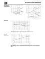
TECHNICAL INFORMATION
Water side The fully watercooled sections are joined by cast iron conical nipples, and distribution
of boiler pipe fitted to the return ensures even the temperature distribution throughout the boiler.
The cast iron sections are to BS.1452 Grade 200 with 7 mm wall thickness. Return and
flow connections to heating system are provided by stub-pipes at the rear of the boiler,
outboard the casing
Under no circumstances should the boiler be fired when its circulation volume is less than
a recommended minimum volume calculated according to the following formula:
The following table provides hydraulic resistances at various water volumes relativ to boiler
Dt flow/return. The difference between flow and return temperatures of the bolier should
not be greater than 20 C to provide convenient operating conditions in the boiler:
Flue design Boilers must be connected to a chimney by using the shortest flue canal possible which
and chimney should be insulated by mineral wool or similar material. Flue canal must be placed at a
installation rising slope of 10°-45° between flue and chimney. Conditions creating higher resistance
to gas flow such as elbows should be avoided in flue canal. The flue canal outlet to the
boiler should not support the weight of chimney.
At discharge from the boiler, the flue gasses should be in a balanced state, consequently,
the function of the chimney is only for the disposal of the flue gasses to atmosphere.
Chimney calculations should be carried out in compliance with the standards. Conditions
of existing chimney should be checked and proper precautions should be taken against
excessive cooling and condensation (such as applying a chimney sheet made of stainless
steel grade 316 and surrounding with insulation). Positive draught conditions must be
avoided. Negative draught conditions should be contained within -3 mm wg. for optimum
boiler performance.
The following table shows typical flue gas volumes at gross flue temperature of 190°C and
ambient air temperature of 20°C.
hm
kWOutput
/
70
3
=
∆
t=10
o
C
∆
t=15
o
C
∆
t=20
o
C
Type
Minimum
Circulation
Water
volume
Hydraulic
Resistance
Water
volume
Hydraulic
Resistance
Water
volume
Hydraulic
Resistance
m
3
/h m
3
/h mbar m
3
/h mbar m
3
/h mbar
MK8 4.6 27.5 57.7 18.3 25.6 13.8 14.7
MK9 5.4 32.5 83.5 21.7 37.2 16.3 21.0
MK10 6.3 37.5 113.1 25.0 50.2 18.8 28.6
MK11 7.1 42.5 145.6 28.3 64.5 21.3 38.5
MK12 7.9 47.5 185.3 31.7 82.5 23.8 51.7
MK13 8.8 52.5 249.0 35.0 110.7 26.3 62.5
MK14 9.6 57.5 305.4 38.3 135.5 28.8 76.5
MK15 10.4 62.5 368.1 41.7 163.7 31.3 92.2
MK16 11.3 67.5 309.5 45.0 137.5 33.6 77.0
MK17 12.1 75.5 384.4 48.3 163.1 36.3 92.0
MK18 12.9 77.5 431.1 51.7 183.2 38.8 107.9
MK19 13.8 82.5 501.4 55.0 211.6 41.3 125.5
MK20 14.6 87.5 578.7 58.3 244.7 43.8 144.8

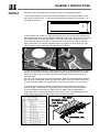
PREPARATIONS BEFORE ASSEMBLY
Boiler room The installation must be arranged in accordance with Mandatory Regulations and Codes
arrangement of Practice. The following sketch shows the recommended minimum dimensions of
clearance around the bolier for servicing and maintenance
Boiler room should not be used for any other applications, floor should always be kept dry
and clean. Any obstacles in front of ventillation openings must be avoided. The boiler room
air openings must conform to the norms prevailing locally.
Any irregular electricity installations in boiler room should be replaced.
The circulating water in boiler and heating system must never be taken out for any
domestic usage.
Water level should be checked periodically with a hydrometer.Nnever add water to the
system when boiler is hot. Never drain the water unless it is necessary.
Should odour is sensed in boiler room, first close the valve before gas flow meter. Never
use match and never smoke in boiler room. Never turn electricity on/off. Ventilate the room
opening doors and windows and consult authorized installer staff or Gas Dealer Company
immediately.
Follow instructions for periodic cleaning and maintenance operations whose procedures
given further in this manual.

PREPARATIONS BEFORE ASSEMBLY
The boilers can be installed directly onto a smooth level floor of non-combustible material.
A steel baseframe and a 50 mm thick mineral wool mat to insulate the underneath of the
boiler are included in the supply. A raised plinth shall be used. It is recommended that
the plinth be at 200 mm high and sized to the dimensions of casing of the boiler given as
in the following table:
Water The system design must provide water flow rates commensurate with boiler output and the
Circulation temperature difference between flow and return should not exceed 20 C, or 25 C at most.
System
The return temperatures due to oil type fired should not be lower than the degrees given in
«Technical Informations» to operate the boiler in non-condensing mode. In this case, your
boiler can be operated without using a by-pass pump and there will be no condensation in
the boiler. As the flow temperature of your boiler can be changeable meeting different heat
requirements of the system without any condensation, the hydraulic circuit no more needs
any devices to adjust the hot water temperature such as three-way valves.
Should the system is operated at temperatures below than those mentioned above, a
by-pass pump or a three/four-way motor vane should be used to increase the return
temperature particularly in conditions natural gas or LPG used.
A by-pass pump must be used, should the system has a three way motor vane, because
of the principle of preventing condensation in the boiler.
Water levels should be checked regularly and any leakages corrected in order to keep
system water make-up to a minimum, because excessive make-up will lead to salt
deposits forming in the boiler waterways causing local overheating and damage to the
boiler sections. Where there is doubt as to the quantity of water make-up, a water meter
should be fitted.
Boiler water systems should be thoroughly flushed and cleaned before a new boiler is
installed and system water should be treated by a reputable specialist and best practice
observed. Consideration should be given to the fitting of sludge traps and strainers if site
conditions warrant them.
Failure to apply and maintain the correct water treatment to prevent the formation of scale
scale and corrosion within the heating system will render all appliance warranties null and
and void.
Recommended dimensions of plinths (mm)
Type
MK8 MK9 MK10 MK11 MK12 MK13 MK14 MK15 MK16 MK17 MK18 MK19 MK20
Width 1130
Lenght
1410 1540 1665 1785 1925 2050 2180 2305 2435 2565 2690 2820 2945
Height 200

PREPARATIONS BEFORE ASSEMBLY
Safety o
f
For heating systems with maximum boiler temperature up to 100 C:
water
circulation The system can be built either open vented or pressurized. In case of open vented heating
system system an open type expansion tank acoording to DIN 4807 Part 2 shall be installed at
the heighest level of hydraulic circuit. Delivery and return lines between expansion tank
and boiler shall be constructed in aacordance with DIN 4750. No globe valves must be
installed on delivery and return safety lines. Safety lines should be attached to inlet and
outlet lines of boiler at points as close as possible to boiler, using the shortest possible
vertical way between expansion tank and boiler.
A hydrometer shall be installed on delivery line from boiler at a same level with top of boiler.
After filling heating system, the minimum water level should be recorded on hydrometer
in order to check water level during operation.
In case of pressurized heating system a pressure relief valve according to TRD 721 shall
also be installed on heating system to ensure safety besides closed type expansion
vessel.
For heating systems with maximum boiler temperature up to 120 C:
In this case, each heating circuit is constructed pressurized and shall be equipped with
diaphragm or spring-tensioned pressure relief valves according to TRD 721.
Each heating system can be equipped with up to three pressure relief valves. For boiler
nominal heat outputs 350 kW and above, the pressure relief valve shall be connected to
an open relaxation pot for safety of system. If this can not be established, an additional
safety temperature and a maximum pressure limiter should be installed on the boiler.
The sizes of diaphragm pressure relief valves on inlet or outlet of boiler according to
boiler nominal heat output are outlined below:
Boiler output in kW 50 100 200 350 600 900
Connection to outlet G 1/2" G 3/4" G 1" G 1 1/4" G 1 1/2" G 2"
Connection to inlet G 3/4" G 1" G 1 1/4" G 1 1/2" G 2" G 2 1/2"

PREPARATIONS BEFORE ASSEMBLY
Requirements For heating systems with maximum boiler temperature up to 100 C, the necessary water
on filling purification shall be in accordance with VDI 2035:
water
Boiler capacity range Nr. Requirements at the filling and auxiliary water
100 < Q in kW <350 1 No requirement is needed, if content of Calcium
Hydrocarbonate (CA(HC03)) is max 2 mol/m³, and if no
more than the triple water filling of the plant does not
take place
350 < Q in kW <1000 2 Like 1, however content of Calcium Hydrocarbonate is
max. 1,5 mol/m³
1000 < Q in kW 3 In this case, quantity of water, which can be fed without
softening, is to be determined after VDI 2035 equation
(9). If the system needs more filling and auxiliary water,
this must be demineralized.
The maximum quantity of water Vmax, which can be re-fed without softening as filling and
auxiliary water, is determinable after equation (9) the VDI 2035 sheet 1:
Vmax in m³ = 0,0313 x Q in kW
/
Concentration of (CA(HC03)) in mol/m³
The quality of water is important. The recommended hardness of water: 1-3 mol/m3
(1 mol/m3=5.6 dH), PH:8-9.5
For heating systems with maximum boiler temperature above 100 C, the following
requirements on circulating water shall also be ensured in accordance with TRD 612:
Salt-free
Salty
Electrical conductivity
≤30 ≤30-100 >100-1500
at 25 C (µS/cm)
pH degree at 25 C 9-10,4 9-10,5 9-10,5
Oxygen (O2) (mg/lt) <1,0 <0,05 <0,02
We strictly recommend to use water treatment products in heating system prior to first
operation of the boiler. Such water pre-commission products will protect the heating
system against any further attack from corrosion or limescale, and thus prevent
Boiler noise,
Sticking pumps,
Radiator cold spots,
Unestimatad thermal shocks on boiler sections,
saving energy and extending whole heating circuit operation life.
For pre-commission of system we will recommend Copal or Alphi-11 protectors from
Fernox Ltd.

ASSEMBLY INSTRUCTIONS
MK Jetstream An MK boiler delivered unassembled consists of following parts:
Delivery Mode
1. Boiler block: A block of sections, smokehood and front door is delivered on a tread for
an easy shipping. The sections are assembled in the boiler room. Refractories for
combustion chamber insulation are mounted on the rear section at the factory. Smokehood
is fixed to rear section and, front door refractories are placed in factory.
Each MK boiler block is shipped in two pieces:
1.1. Standart pallette of intermediate/rear sections + smokehood
From MK 8 to MK 14, four pieces of intermediate sections, rear section, and smokehood
is delivered on one pallette. From MK 15 to MK 20, nine pieces of intermediate sections,
rear section and smokehood is delievered on one pallette. Smokehood is fixed to rear
section, rear cleaning covers and refractory of combustion chamber on rear section are
fitted to their correspondant places before shipment from factory. Intermediate sections
are shipped disassembled
1.2. The remaining pallette of intermediate sections + front section
The rest of intermediate sections, front section and front door of boiler are shipped on one
pallette. Intermediate sections are delivered disassembled. Front door refractories and
insulations are placed and fixed before shipment. Front door is fixed temporarely onto front
section for a secure shipment. Before assembly of boiler in site, front door should be
detached from front section. The materials used in the assembly of the boiler block such
as nipples, fiberglass ropes,flow and return connections, retarders are delivered with in
remaining palette of intermediate sections+ front section group.
2. Casing/insulation box: This box contains all casings and baseframes (if required)
together with all insulations of an MK boiler. Auxillary piping system for series MK 12 and
above, and retarders set of boiler, and control panel are also supplied in this box.

ASSEMBLY INSTRUCTIONS
Assembly o
f
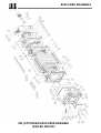
Numbers in the parenthesis refer to position numbers in the exploded drawing.
Boiler Group
1. Place steel profiles (174) which are used as baseframes of the boiler parallel to each
each other as shown in Fig. 1. There are four baseframes for MK 8-10, six for MK 11-15,
and eight for MK 16-20.
2. Start with the rear section (1), clean all rope grooves on the section using a wire brush.
Clean nipple ports using cloth and paraffin. Apply adhesive to the rope grooves on the front
side of the section Fit continuous lengths of 12 mm dia. Rope (5) in each groove of the
section starting with the outer grrove. Tape the ends of each rope to avoid unravelling.
Apply red lead dye onto nipples and place nipples (4) squarely in each nipple port, and
using a wooden mallet, lightly tap nipple into the port to secure.
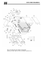
3. Take an intermediate section (3) and prepare the section as described above. Do not fit
rope into the grooves on the side of intermediate section facing towards the rear section.
Likewise, fit ropes only to one side of the other intermediate sections which are to be
assembled later.
Place the rear section at the end of the baseframes. With its unroped side facing towards
the rear, fit the intermediate section squarely onto nipples of the rear section and secure
by using a wooden mallet. Ensure that rope on rear section remains in correct position
4. Continue boiler assembly repeating the same procedures with other intermediate
sections. Apply "Compression Tools" passing them through bottom and top nipples as
shown in following scheme and accordance with the table headed "Usage order of
compression tools", until the rope between each section is firm. The gap between each
section should be 4-5 mm (check the gap using a screwdriver blade).
900

ASSEMBLY INSTRUCTIONS
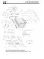
After each application of compression tools, fit staybolts (to secure group of sections to
each other) (8,9) with M16 nuts (11) and washers (10).
Do not use excessive force to tighten the nuts up on the staybolts, from 48 to 54 Nm
(35 - 40 lbf/ft) torque is recommended.
5. Prepare the front section (2) for the assembly. Apply special adhesive called fiberfrax
suppllied in accessory box into grooves of front section facing towards the front door. Fit
fiberglass rope braided 16x16 mm (29) in the grooves of the front section. Fit the front
section and make final usage of Boiler Compression Tools and correctly align the sections.
Fit staybolts (8,9) with M16 nuts (11) and washers (10).
Fit two 2" plugs (22) into the ports of front section. For MK 8 and 9, fit plug 1 1/2" (181) on
top of the front section. For MK 10 and above, fit elbow 1 1/2" (182) on top of the front
section, and auxillary pipe (184) to the elbow. For MK 12 and above, there are two auxiliary
pipes. In that case, bring them together using pipe union (183). Piping from the elbow
should be raised slightly and connected into the main rear flow outside the boiler without
fouling the top and rear casing. Fit studs M16x65 (20) to return and flow connections of
the rear section.
Hydraulic test Fit 1/8" plug (155) supplied in accessory box into 1/8" hole on top of the rear section (with
P2-A standard control panel, this hole is not used). For 1/2" and 3/8" instrument tappings
on top of the rear section, use 1/2" and 3/8" pockets for bulbs supplied within the standard
control panel or any suitable plugs. Fit a 3/4" plug into drain connection of the rear section.
Use hydraulic test apparatus of MK boiler. Fit bottom test flange with two globe valves and
test gasket to return connection. Fit blank flange and the other gasket to flow connection
as shown in following scheme. Fit closing piece with a gate valve to the end of the auxiliary
pipe to.
Connect a hydraulic press to one of the globe valves on
test flange fitted to return connection. Fill the boiler with
water by connecting the other valve on test flange to the
water circuit. Meanwhile, release the air left in the boiler
via pocket bulbs holes on top of the rear section. When
the water comes out of the holes, fix the pocket bulbs
again. Turn the valve connected to circuit off and turn the
other valve connected to the hydraulic press on.
Pressurize the system via the pump on hydraulic press
until the pressure gauge reaches the test pressure.
Usage order of compression tools
Model
First application
(Nr of sections)
Second
application
(Nr of sections)
Third application
(Nr of sections)
Fourth
application
(Nr of sections)
Fifth application
(Nr of sections)
MK 8 4 8
MK 9 5 9
MK 10 4 8 10
MK 11 4 8 11
MK 12 4 8 12
MK 13 5 8 13
MK 14 4 8 11 14
MK 15 4 8 12 15
MK 16 4 8 12 16
MK 17 5 9 13 17
MK 18 4 8 12 13 18
MK 19 4 8 12 16 19
MK 20 4 8 13 17 20

ASSEMBLY INSTRUCTIONS
Hydrostatic test shall be carried out at a pressure gauge of 1.43 x P; where, P is the
maximum operating pressure of boiler. Duration of test should be at least 30 minutes.
The hydrostatic test must always be carried out before boiler being jacketed or heat
insulated, and connected to heating circuit.
After hydrostatic test, "Boiler Assembly Certificate" shall be filled in and signed by the
erector/installer. In order to warranty terms of boiler to be put into operation, make sure
that this certificate is completed, signed, and sent to manufacturer. We recommend you
to ask for a copy of assembly certificate from erector/installer.
For installations in Germany, every hydrostatic test shall be carried out under
technical supervision of TÜV Rheinland.
We recommend you to ask your erector/installer to record the data of boiler group such
as boiler shipment group serial numbers, production date etc. which will help both
installer and manufacturer use for optimum customer care and technical feedback.
6. Fit distribution pipe (271/272) with gasket (12) squarely into the return connection in any
position as shown in following pictures. Fit flanged stub-pipes (13) with their gaskets (12)
to the flow and return connections on the rear section. Fix the stub-pipes using M16 nuts
(11) and washers (10).
7. Fit second pass raterders (67,70,72) in each of the four inner passages. Fit third
pass retarders (76,79,83) in each of the four corner passages with the upon ends of the
tubes facing towards the front section. After placing all the retarders, pull them towards
the front section side as much as possible.

ASSEMBLY INSTRUCTIONS
Jasket assembl
y
1. Fit cast iron hinges (229) used for carrying front door onto front section using
MK 8-11 two pieces of M12x50 allen screws (32) for each hinge. When fitting hinges to
front door, place front support sheets (247) between front door and hinges.
2. Place boiler block insulation (265) squarely on top boiler block. For MK 8 and
9, there is one piece of boiler block insulation. However, for MK 10 and 11,
boiler block insulations consitst of two equal parts(265,266). For these series,
place two pieces of block insulations placing one after another. After placing
block insulations, secure both ends of insulation part/parts to lower staybolts by
using 4 insulation springs (251) for each insulation part Make a hole of 75 mm
in diameter on side of insulation piece that corresponds to sensor pocket
fitted on top of rear section.
3. Fit the pieces of the insulation underneath the boiler block (149). Ensure that
aluminium backed faces are facing downwards.
4. Fit left and right rear support sheets (249) to smokehood by using M12 nuts
(23) and A13 washers (267). Rear support sheets are fixed to rear section by
the help of M12x60 studs (232) that are used for assembly of smokehood to rear
section.
5. Fit left and right hand side lower casings (LH is pos. 237, and RH is pos.236)
onto front and rear support sheets as shown in following photos. Fix lower side
casing onto front support sheet (248). Fix lower side casing onto rear support
sheet by using two pieces of M8x20 setscrews (245) and A9 washers (246).
6. Fit a special pin(250) securing it via M4 nut (214,215) on each LH and RH side
upper casing. These special pins will help upper side casings to be secured
against vibration during operation.
7. Fit left and right hand side upper casings (LH is 235, and RH is 234) on top
of LH and RH side lower casings securing onto front and rear support sheets.
Make sure that special pin on upper side casing coincides with the hole on
lower side casing. Fix upper side casing onto rear support sheet by using two
pieces of M8x20 setscrews (245) and A9 washers (246). Fix upper side casing
onto front support sheet by using two pieces of special M8x20 setscrew (248).
FRONT VIEWREAR VIEW

ASSEMBLY INSTRUCTIONS
8. Fit rear insulation LH and RH pieces (242) onto smokehood as shown in following photo.
9. Fit rear casings (240 and 241) onto smokehood by using four special M8x20 setscrews
(248). Rear casing consists of two simetric parts (LH is pos. 241 and RH is pos. 240) like
rear insulations. After fitting the other part of rear casing, connect corresponding sides of
rear casings together by 3 self tapping screws to secure.
10. Apply fiberfrax adhesive into grooves on cleaning cover ports of smokehood, and fix
rope fiberglass braided 9 mm. dia. (244) into the grooves There are two cast iron cleaning
covers. Cleaning covers (243) are fitted onto smokehood by using 2 pieces of M8x20
setscrews (245) and A9 washers (246).
11. Likewise in Clause 6, fit two special pins (250) securing them via M4 nuts (214,215) on
each LH and RH upper side casings.These special pins will help top casings to be secured
against vibration during operation. Place top casings front and rear pieces (238 and 239) on
top of upper side casings.
12. Before assembly of front door, first decide the side of the hinging (from LH or RH
opening). Screw hinge pins (230a) into threaded holes on correspondant hinges (LH or RH
due to opening of front door). Screw an M20 nut onto each hinge pin as shown in following
photo. Hang front door (227) on M20 nuts (36) to establish the attachment to front door.
The position of front door up and downwards is adjusted by these M20 nuts.
Adjust the alignment of front door to ensure that it compresses squarely onto fibreglass
rope on front section. Fix front door to front section using four pieces of M16x40 setscrews
(228) and A17 washers (223).

ASSEMBLY INSTRUCTIONS
13. Screw in the special setscrew(230b) into hole of upper hinge by using a screwdriver
in order to make front door aligned parallel to floor while closing.
Lift the front door by using a wrench from the bottom of the special setscrew during
closing.
14. Secure the door by using four M16x40 setscrews and washers.
Securing
Points
Adjustment point
of align to parallel

ASSEMBLY INSTRUCTIONS
Jasket assembl
y
1. Apply the same procedure as described in Clauses 1, 2, and 4 of previous chpater, for
MK 12-20 series MK 12 to MK 20.
2. Fit auxillary baseframes for side casing assembly for series MK 12 to 20. First, fix
front/rear baseframes (260) securing it by an M16 nut (11,10) on correspondant end of
lower staybolts (8 or 9). Apply the same procedure for opposite side (see following photos).
As all front/rear baseframes are all the same in terms of construction, any mis-placement
is prevented.
Fit intermediate baseframes (261) to front and rear baseframes (260) using four pieces of
special M8x20 setscrews (248) for each side.
3. Place boiler block insulation front piece (265,266) on top of boiler block, and secure
insulation to lower staybolts by insulation springs(251) as described in Clause 2 of previous
chapter.
4. Fit right and left hand side lower casing front pieces (LH is pos. 257, and RH is pos.
256) on side baseframes (260+261+260), fixing them onto front support sheets (247) via
two pieces of special M8x20 sectscrews (248). Additionally secure lower casing front
pieces onto side baseframes by a a special M8x20 setscrew (248) for each. See following
photos.
5. Fit LH and RH lower side casings rear pieces on LH and RH side baseframes (260+261),
fixing them onto rear support sheets (249) via M8x20 setscrews (245) and A9 washers(246).
Additionally secure lower casing rear pieces onto side baseframes by a special M8x20
setscrew (248) for each.

ASSEMBLY INSTRUCTIONS
6. Fit eight pieces of special assembly pin (264) into clinched nuts on each vertical
baseframe (262). Fix vertical baseframe onto side casing lower parts front piece (256 and
257), first passing lower two special assembly pins (264) through holes on items 256 and
257, and then pushing item 262 downwards (see photo on the left side). Fix upper support
sheet (263) onto LH and RH vertical baseframes by M8x20 setscrews (245) and A9
washers (246) (see photo below). Item 263 may be placed either with its bending side
towards forward or backward so that it can always be supported by upper staybolts for a
secure baseframe system.
7. Place remaining pieces of boiler block insulations (265,266). If placement of boiler block
insulation piece is blocked by upper support sheet, cut this insulation sheet to complete
the placement.
upper casing. These special pins will help upper side casings to be secured
against vibration during operation.
8. Fit a special pin (248) securing it via M4 nut (214,215) on each LH and RH side upper
casing front and rear pieces. These special pins will help upper side casings to be secured
against vibration during operation. Fit LH and RH upper side casings front pieces (LH is
pos. 253, RH is pos. 252) onto coinciding upper piece, securing them on front support
sheets via two pieces of special M8x20 setscrews (248) as shown in following photo. When
fitting upper side casings, make sure that, the pins (264) on item 262 lock correspondant
holes on side casings.
9. Fit LH and RH upper side casings rear pieces (LH is 255, RH is 254) onto lower side
casings, following the same procedure. For assembly of top casings, rear insulations and
rear casings, follow the same procedure with MK 8 -12 series.
Page is loading ...
Page is loading ...
Page is loading ...
Page is loading ...
Page is loading ...
Page is loading ...
Page is loading ...
Page is loading ...
Page is loading ...
Page is loading ...
Page is loading ...
Page is loading ...
-
 1
1
-
 2
2
-
 3
3
-
 4
4
-
 5
5
-
 6
6
-
 7
7
-
 8
8
-
 9
9
-
 10
10
-
 11
11
-
 12
12
-
 13
13
-
 14
14
-
 15
15
-
 16
16
-
 17
17
-
 18
18
-
 19
19
-
 20
20
-
 21
21
-
 22
22
-
 23
23
-
 24
24
-
 25
25
-
 26
26
-
 27
27
-
 28
28
-
 29
29
-
 30
30
-
 31
31
-
 32
32


elco Alpha Jetstream MK Installation guide
- Type
- Installation guide
Ask a question and I''ll find the answer in the document
Finding information in a document is now easier with AI
Related papers
Other documents
-
 T & S Brass & Bronze Works CW-4B-60VB Datasheet
-
 Rima Heating Systems ON-09 Installation, Operation & Maintenance Manual
-
 Smith Cast Iron Boilers 28HE-17 User manual
-
Smith Cast Iron Boilers 28A-5 User manual
-
Buderus Logano G315 Assembly, Maintenance And Operating Instruction
-
 Smith Cast Iron Boilers 19A SERIES User manual
-
Kmart 43316731 User manual
-
REMEHA P 420 Installation and Service Manual
-
Buderus Logano G215 US Installation And Maintenance Instructions Manual
-
Burnham Series V11 Operating instructions


