Page is loading ...

A s s e m b l y, Maintenance and
Operating Instructions
Buderus G315 Boiler
Save These Instructions!
5647 853-5/98 USA
This assembly, maintenance and operating
manual must be kept near the boiler!
Buderus Hydronic Systems, Inc.
16 Industrial Way
Salem, New Hampshire 03079
Tel: (603) 898-0505 • Fax: (603) 898-1055
Boiler installed by:
(contractor’s address)
Boiler installed on:
(date of installation)
Buderus Hydronic Systems, Inc. reserves the right to make changes without notice due to continuing engineering and technological improvements.
G315

TABLE OF CONTENTS
1
General Guidelines 3
2
Boiler Operating Data 4
3
Technical Data 5
4
Boiler Foundation and Minimum Boiler Clearances 6
5
Assembly Tools/Tools Req’d for Boiler Assembly 7
6
Boiler Assembly 8-11
7
Hydrostatic Test 12
8
Installation of Boiler Components 13-15
9
Installation of Insulation & Boiler Jacket Panels 16-19
10
Installation of Hydronic Control Components 20
11
Maintenance Instructions 21-23
12
Optional Noise Reduction Equipment 24
13
Shipping Component Listing 25
14
Supply Temperature Control 26
1

General Guidelines 1
3
General guidelines
Installation, maintenance and service of this boiler must only be carried out by a qualified contractor.
The assembly sequence is essential to reliable operation of the boiler and associated heating system. The
boiler can be assembled, hydrostatically tested and operated without boiler insulation and jacket panels.
These items can be installed at a later date without disrupting boiler operation.
NOTE: A minimum supply temperature of 122° F must be maintained during burner operation. Controls
must be provided that will shut off circulation through the boiler when the supply temperature
drops below 122° F. This requirement applies only during burner operation. There is no
minimum return water temperature requirement.
All work shall be performed in strict accordance with the requirements of state and local regulating agencies
and codes dealing with boiler installations. Initial start-up must be performed by qualified personnel.
After start-up the owner or its representative should be instructed about the boiler operation and be given
the assembly and maintenance manual.
Boiler cleaning and maintenance must be carried out once annually. This includes an overall check of the
heating system. Any discrepancies must be corrected immediately.
NOTE: To perform the hydrostatic pressure test after the boiler is assembled, 2-2” or 3” caps, 3/4”, 1”
and 2” plugs and a 3/4” air vent may be needed. These items are not furnished with the boiler.
NOTE: This manual is for reference only. The manual does NOT purport to address all design,
installation and safety considerations. It is the responsibility of the user of this manual to
determine the applicability and safety of each individual application and ensure its compliance
with local building codes.
It is expected that the user/installer is a licensed heating contractor with knowledge of accepted
industry practices for the installation and maintenance of the equipment and various applications
of the equipment involved.
2

Technical Data 3
5
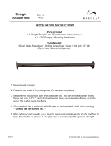
Table 1: Boiler Dimensions
Table 2: Technical Specifications
Gross Output (Btu/hr.) 358,000 478,000 580,000 682,000 785,000
No. of Sections 5 6 7 8 9
Overall Boiler Length L
G
(In.) 44
1
/4 50
1
/2 56
3
/4 63
1
/4 69
1
/2
Boiler Block Length L
K
(In.) 38
1
/4 44
1
/2 50
3
/4 57 63
1
/2
Minimum Boiler Width B
E
(In.) 28 28 28 28 28
Fire Box Depth L
F
(In.) 31 37
1
/2 43
3
/4 50 56
1
/4
Fire Box Diameter (In.) 15
3
/4 15
3
/4 15
3
/4 15
3
/4 15
3
/4
Fire Box Volume (Cu.Ft.) 5.19 6.39 7.59 8.79 9.99
Dry Weight (Lbs.) 1197 1391 1585 1779 1973
Water Content (Gals.) 37.8 45.2 52.6 60.0 67.4
Operating Weight (Lbs.) 1512 1768 2024 2280 2535
Vent Connection Size (In.) 7 7 7 7 7
Door Thickness T (In.) 5 5 5 5 5
Fig. 1
Gross Output (Btu/hr.) 358,000 478,000 580,000 682,000 785,000
No. of Sections 5 6 7 8 9
Boiler HP 10.7 14.3 17.4 20.4 23.5
Net IBR Rating (Btu/hr.) 311,000 416,000 504,000 593,000 683,000
Max Input Oil (GPH) 3.0 3.85 4.7 5.5 6.4
Max Input Gas (Btu/hr.) 420,000 540,000 660,000 770,000 896,000
Fire side heating surface (Sq.ft.) 50.6 62.4 74.3 86.1 96.9
Firebox Pressure (In. W.C.) .18 .32 .50 .71 .75
34
3/4
”
40
3/4
”
17
3/4
”
17
3/4
”
max.
9”
7”
L
K
11
1/4
”
L
F
T
37”
32
1/4
”
L
G
25
1/2
”
B
E
3/4”
Drain
1”
Top View
Rear View
Side ViewFront View
Supply
Return
2 Boiler Operating Data
4
Boiler operating ratings
Maximum supply temperature: 248°F (120°C)
Maximum operating pressure: 58 psi (4 bar)
Water quality requirements
Fill water requirement: water with alkalinity < 200 mg/li for initial system filling.
Make-up water requirement: water with alkalinity < 30 mg/li
System water requirements:
pH value (@ 77°F): 9.0 - 10.0
Acid capacity: 3.0 - 50 mg/li
Oxygen (O2): .01%
Phosphate (P205): 2.5 %
Sodium sulfate (Na2SO3): 1 - 4%
For overall system protection, it is recommended to install a filter and sludge removal system
in the boiler return piping.
Any approved (based on application testing at burner manufacturer’s facilities) oil or power gas
burner can fire into G315 boilers. Burners with low fire start or two stage firing are recommended.
The high fire setting on the burner should match the rated output of the boiler to prevent
condensation in the heat exchanger. The CO volume percent in undiluted, dry flue gas should
not exceed .04% (400 ppm).

Technical Data 3
5
Table 1: Boiler Dimensions
Table 2: Technical Specifications
Gross Output (Btu/hr.) 358,000 478,000 580,000 682,000 785,000
No. of Sections 5 6 7 8 9
Overall Boiler Length L
G
(In.) 44
1
/4 50
1
/2 56
3
/4 63
1
/4 69
1
/2
Boiler Block Length L
K
(In.) 38
1
/4 44
1
/2 50
3
/4 57 63
1
/2
Minimum Boiler Width B
E
(In.) 28 28 28 28 28
Fire Box Depth L
F
(In.) 31 37
1
/2 43
3
/4 50 56
1
/4
Fire Box Diameter (In.) 15
3
/4 15
3
/4 15
3
/4 15
3
/4 15
3
/4
Fire Box Volume (Cu.Ft.) 5.19 6.39 7.59 8.79 9.99
Dry Weight (Lbs.) 1197 1391 1585 1779 1973
Water Content (Gals.) 37.8 45.2 52.6 60.0 67.4
Operating Weight (Lbs.) 1512 1768 2024 2280 2535
Vent Connection Size (In.) 7 7 7 7 7
Door Thickness T (In.) 5 5 5 5 5
Fig. 1
Gross Output (Btu/hr.) 358,000 478,000 580,000 682,000 785,000
No. of Sections 5 6 7 8 9
Boiler HP 10.7 14.3 17.4 20.4 23.5
Net IBR Rating (Btu/hr.) 311,000 416,000 504,000 593,000 683,000
Max Input Oil (GPH) 3.0 3.85 4.7 5.5 6.4
Max Input Gas (Btu/hr.) 420,000 540,000 660,000 770,000 896,000
Fire side heating surface (Sq.ft.) 50.6 62.4 74.3 86.1 96.9
Firebox Pressure (In. W.C.) .18 .32 .50 .71 .75
34
3/4
”
40
3/4
”
17
3/4
”
17
3/4
”
max.
9”
7”
L
K
11
1/4
”
L
F
T
37”
32
1/4
”
L
G
25
1/2
”
B
E
3/4”
Drain
1”
Top View
Rear View
Side ViewFront View
Supply
Return
2 Boiler Operating Data
4
Boiler operating ratings
Maximum supply temperature: 248°F (120°C)
Maximum operating pressure: 58 psi (4 bar)
Water quality requirements
Fill water requirement: water with alkalinity < 200 mg/li for initial system filling.
Make-up water requirement: water with alkalinity < 30 mg/li
System water requirements:
pH value (@ 77°F): 9.0 - 10.0
Acid capacity: 3.0 - 50 mg/li
Oxygen (O2): .01%
Phosphate (P205): 2.5 %
Sodium sulfate (Na2SO3): 1 - 4%
For overall system protection, it is recommended to install a filter and sludge removal system
in the boiler return piping.
Any approved (based on application testing at burner manufacturer’s facilities) oil or power gas
burner can fire into G315 boilers. Burners with low fire start or two stage firing are recommended.
The high fire setting on the burner should match the rated output of the boiler to prevent
condensation in the heat exchanger. The CO volume percent in undiluted, dry flue gas should
not exceed .04% (400 ppm).

Assembly Tools/Tools Req’d for Boiler Assembly 5
Assembly tools and auxiliary assembly materials
✔ Boiler assembly tool rods size 2.2 (2 pieces)
✔ Wooden or rubber mallet
✔ Half-round rough file
✔ Flat head and Phillips screwdrivers
✔ Flat chisel, steel strips for boiler support
✔ Metric wrenches sizes 13, 19, 24, 36 and socket
✔ size 19 (US equivalent sizes may also be used)
✔ Cleaning rags, machine oil, gasoline or paint
thinner, level, steel wire brush, tape measure,
chalk.
Boiler assembly tool components
7
No. of Sections Assembly Tool Extension Piece Total Tool Length (ft)
Table 4. Assembly tool requirements
Fig. 5
Tightening Nut
Assembly Tool
85”
Straight Pin
Stop
Flange
Pressure
Bearing
Pressure
Bearing
Small
Pressure
Flanges
5-9 1 0 7
Boiler foundation preparations
It is required that the boiler is placed on a level, smooth
concrete base, of sufficient strength. The width of the
platform must be 33 1/2”. Length L
1
is the platform
length. It is required to cement in either a 4” x 1/4” flat
steel plate or a 4” x 2” x 1/4” angle iron, as shown in
Figure 2; Table 3 shows dimensions.
Minimum wall clearances
The recommended wall clearances must be observed in
order to open the burner door, assemble the boiler and
allow sufficient access for boiler maintenance.
(See Figures 3 and 4 for details).
The burner door is field adjustable to hinge right or left.
Recommended clearances:
Wall clearance W1: minimum 12”.
Wall clearance W2: Burner length A + 4”, minimum 43”.
Wall clearance W3: Boiler length L + 40”.
Wall clearance W4: 1/2 Boiler length + 20”.
Absolute minimum clearances:
Wall clearance W1: minimum 12”.
Wall clearance W2:* minimum 12”.
Wall clearance W3: Boiler length L or minimum 86”.
Wall clearance W4: 36”.
Note: Wall clearance W3 can be reduced to 4 feet for
assembled boilers. Boiler cleaning will now require
use of segmented brushes.
*Requires burner removal during cleaning.
4 Boiler Foundation and Minimum Boiler Clearances
Fig. 2
Fig. 3
Fig. 4
6
16”
7
3 / 4
”
7
3 / 4
”
Table 3: Foundation and support strip lengths
No. of Sections Length LI (In.) Length L2 (In.)
5 36 28
3
/4
6 42
1
/4 35
7 48
1
/2 41
1
/4
8 54
3
/4 47
1
/2
9 61 54
33
1 / 2
”
4 ”
4 ”
4 ”
20”
3
1 / 2
”
10”

Boiler block sectional arrangement
The boiler is always assembled starting with the rear section
and finishing with the front section.
The arrow markings on the sections must point to the rear
(Fig. 6) and use the sequence in Table 5.
Assembly of individual boiler sections
• Remove the nuts and washers from the rear and
front sections prior to boiler assembly.
• Note the arrow marking on each section. These
arrows are located on the top left and right of
each section and must point to the rear during
boiler assembly (Fig. 6).
• Assemble the boiler on a smooth hard surface
with flat steel plates underneath to permit easy
sliding of sections.
• Position and align the rear section upright in
final location and secure it from falling over
(Fig. 7).
• To reduce the risk of injuries, support the boiler
section or secure it with an overhead lifting device.
6 Boiler Assembly
8
315/5 1 3 1
315/6 1 4 1
315/7 1 5 1
315/8 1 6 1
315/9 1 7 1
Model
No. of
Front Section
No. of
Midsections
No. of
Rear Section
Table 5: Boiler section arrangement
Fig. 6
Fig. 7
Flue gas
collector
Assembly
arrow marking
Rear
section
Front
section
Middle sections
CAUTION: The work area must be well
ventilated during boiler assembly .
WARNING: Keep Buderus Haftgrund 181 primer
away from flam e! Do not smoke
during assembly! Do notpour
Buderus Haftgrund 181 primer down
open drains!
• File off any burrs from the nipple ports (Fig. 8).
• Clean the sealing surfaces of the nipple ports with
a rag soaked in thinner or gasoline. Wipe dry.
• Evenly coat the nipple port sealing surfaces with
the orange sealing compound (Leinolmennige)
using the brush provided (Fig. 9).
• Clean the sealing grooves for sealing the flue side
of the boiler using a steel wire brush. Make sure
surfaces are dry, clean and free of any oily residues.
• Apply the Buderus Haftgrund Primer 181 to all
sealing grooves using a small paint brush (Fig. 10).
• The sealing of the flueway of each section is
achieved with the sealing cord. The sealing
cord can be installed 5 to 15 minutes after
the application of the primer.
Fig. 8
Fig. 9
Coat with
orange sealing
compound
Fig. 10
Boiler Assembly 6
9
Sealing grooves

Boiler Assembly 6
Pull sections together with boiler assembly tool
• Place assembly rods through upper and lower ports
as shown (Fig. 14).
• Slide small pressure flange on each end of the lower
assembly rod.
• Thread the pressure flanges on the rods.
• Slide stop flange on upper rod, insert straight pins
on both rods.
• Lock flanges on assembly rods with straight pins in
place by hand tightening assembly tools.
• Ensure that the tools are centered in the ports by
having flanges properly located.
• Use socket wrenches provided to draw sections
together evenly. Stop tightening when boiler
sections abut metal to metal. Unscrew assembly
tools.
NOTE: Inspect seating to ensure nipples ar e
seated square. Never draw more than
one section at a time to avoid damage
to the push nipples and ports.
• Repeat boiler assembly procedure for subsequent
sections as detailed on pages 9-11.
NOTE: After the boiler block has been
drawn together, loosen the tools,
but do not remove.
Fig. 14
Fig. 15
• Install tie bars in the cast iron slots on the left and right sides of the upper and lower nipple ports
(Fig. 15).
• Slide one spring assembly on each tie bar at the rear section. Do not disassemble the spring assemblies!
Place a washer and nut at both ends of each tie bar. Install a second nut on each tie bar at the front of
the boiler.
• Hand tighten each nut first; then tighten the tie bar nuts on one end by 1 to 1
1/2
turns with a wrench.
• Level the boiler horizontally and vertically. Now, remove the assembly tools.
11
Assembly rod
Pressure flange
Assembly rod
Tie bars
Tie bar
• Insert the elastic sealing cord (“Dichtschnur”) into the
sealing groove only on the front side of the rear
section. Start at the top and press lightly to adhere to
the Primer 181 (Fig. 11).
• Unroll sealing cord and remove paper backing during
installation. Cut sealing cord to length with a pair of
scissors or knife. Butt sealing cord ends tightly
together or overlap cord ends 1” for proper sealing.
• Clean a set of push nipples with a rag soaked in
thinner. Wipe dry. A set consists of the 4
3/4
” x 2”
top nipple and the 2
1/4
” x 2” bottom nipple.
• Evenly coat slightly over half the width of the outer
surface of each push nipple with the orange sealing
compound.
• Insert the coated side of the nipples into the ports.
• Set nipples in place by tapping evenly with a rubber
or wooden mallet. Make sure the nipples remain
perfectly aligned with the boiler section (Fig. 12).
NOTE: If a burr on the push nipple occurred
during nipple insertion, file it off
immediately !
• Finish coating the outer surface of the push nipples
with orange sealing compound.
• Clean and coat nipple ports of intermediate section
with orange sealing compound. Also clean flueway
sealing grooves.
This completes the preparation of the joint between the
rear section and the first intermediate section.
Check: 1. Both push nipples installed evenly with the
rear section and nipples and ports fully
coated with orange sealing compound.
2. Sealing cord is properly installed in all
sealing grooves.
• Position intermediate section in front of rear section
and hang from upper push nipple. It may be
necessary to lift up the intermediate section at the
bottom with a bar. Arrow markings must point to
the rear.
• After aligning ports with push nipples, tap against the
intermediate section with the mallet to seat it on the
push nipple.
6 Boiler Assembly
Fig. 12
Fig. 11
Fig. 13
Sealing
groove
Coat with orange sealing compound
Coat with
primer 181
10
Coat with orange
sealing compound
Sealing cord

Flue gas collector installation
• Install the pliable sealing rope in the groove of the
rear section.
• Place the flue gas collector on the studs and tighten
with washers and nuts provided to ensure a gas
tight seal (Fig. 18).
Installation of rear section clean out co vers
• Install sealing ropes into grooves around cleaning
covers.
• Place cleaning cover on studs provided (Fig. 19).
Secure with washers and nuts provided to ensure
a gas tight seal.
Installation of return header pipe
• Place gasket over return header pipe (Fig. 20).
• Insert the return header pipe into upper port from
the front of the boiler (Fig. 20).
• The tab on the header pipe must be aligned with
the recess in the front boiler section. This locks the
header pipe into proper position and ensures that
the outlet openings are positioned correctly
to provide optimum water distribution.
• Install blank flange on studs and secure with nuts
and washers.
Installation of Boiler Components 8
Fig. 18
Fig. 19
Fig. 20
13
Studs
Sealing rope
Clean-out covers
Upper front port
recess
Tab
Gasket
Return
header
Blank flange
Boiler
rear
7 Hydrostatic Test
Hydrostatic Test
Preparing for the hydrostatic test
• A pop-off relief valve is recommended on cold water
feed line to prevent over pressurization.
• Install return header pipe per instructions on page 13.
• Seal the front ports with blank flanges and gaskets.
• Install return header or flange on the lower tapping
with gasket provided (Fig. 16).
• Install supply header at the top tapping of the rear
section. See Chapter 10, page 20 for details. Install a
temporary air vent (not provided) in one tapping.
• Cap off return and supply headers. (Blank flanges,
gaskets or plugs not provided).
• Install fill/drain valve at the lower rear connection
(Fig. 16).
• Install long shank well into 3/4” tapping of rear section.
• Fill the boiler. Vent the boiler at the air vent until water
appears. Close the vent and pressurize the boiler.
• The assembled boiler shall be subjected to a hydrostatic
test pressure not less than 1
1/2
times the maximum
allowable working pressure. The maximum test pressure
shall not exceed the required test pressure by more
than 10 psi.
• If a nipple port connection is leaking, bleed off test
pressure, drain water through the fill/drain valve,
remove the four tie and the return header pipe rods.
• Split the boiler at the leaking joint by driving chisels at
the top and bottom between the sections (Fig. 17).
• Remove old nipples and clean ports as shown on
page 9. Reinstall flue sealing material. Material can be
reused. Reassemble per instructions on pages 10-12.
NOTE: Always use new push nipples when
reassembling the boiler.
• Repeat the hydrostatic test to ensure no leaks.
• Install relief valve after the hydrostatic test.
Fig. 16
Fig. 17
Chisel
Chisel
12
Fill and drain
valve (3/4”)
Lower rear
connection
3/4” tapping
Return
header
Supply
header

Flue gas baffle plates
• Flue gas baffle plates are factory installed in an
assembled boiler. Remove corrugated card board
from baffle plates and insert plates as shown in
Figure 21.
NOTE:Install the baffle plates per schedule below.
Burner Door
• Attach sealing rope to front section by applying
several drops of glue (P/N 422841) every 6” in the
sealing grooves surrounding the combustion
chamber and the outer area of the front section
(Fig. 22).
• Insert the permanent pliable sealing rope in the
grooves on the front section.
• The burner door hinge supports are factory
installed on the right side. Remove and mount
them on the opposite side with (2) M12x35 bolts
for a left hanging door if required.
• Secure the door hinges, if required, with (2) M12x35
bolts to the proper side of boiler front section
(Fig. 22).
• Hang the burner door on the door hinges.
8 Installation of Boiler Components
14
Fig. 21
Flue gas baffle plates
Fig. 22
Door hinge
support
Door hinges
Table 6: Baffle Plate Arrangement
No. of Sections Number of Baffles Length (in) Placement
5 4 14
1
/4” top & bottom (left & right)
6-7 4 17
1
/4” top & bottom (left & right)
8 4 14
1
/4” top & bottom (left & right)
9 4 8” top & bottom (left & right)
Flue gas baffle plates
Sealing rope
Installation of Boiler Components 8
• Hang and close burner door and tighten evenly
with the (4) M12x45 burner door bolts (Fig. 23).
• Cut and drill the burner mounting plate according
to burner specifications. (The burner plate can be
cut by Buderus Hydronic Systems per specifications
submitted with the boiler order).
• Mount burner mounting plate to burner door. Seal
with 1/2” diameter sealing rope.
• Cut burner door insulation material to conform to
burner tube diameter.
• Mount burner per burner manufacturers instructions.
Fill burner door with insulation per instructions below.
• Cover burner tube and sight glass port with
paper to prevent filling these areas.
• Mix insulating cement with water to pulp
consistency.
• Fill any spaces between burner door insulation and
burner tube with the insulating cement (Fig. 24).
Fig. 23
Fig. 24
15
Burner mounting plate
1/2” dia. sealing rope
Sight glass
2
3/4
”
5”
Insulating cement
M 12 x 45
M 12 x 45
Burner mounting plate

Flue gas baffle plates
• Flue gas baffle plates are factory installed in an
assembled boiler. Remove corrugated card board
from baffle plates and insert plates as shown in
Figure 21.
NOTE:Install the baffle plates per schedule below.
Burner Door
• Attach sealing rope to front section by applying
several drops of glue (P/N 422841) every 6” in the
sealing grooves surrounding the combustion
chamber and the outer area of the front section
(Fig. 22).
• Insert the permanent pliable sealing rope in the
grooves on the front section.
• The burner door hinge supports are factory
installed on the right side. Remove and mount
them on the opposite side with (2) M12x35 bolts
for a left hanging door if required.
• Secure the door hinges, if required, with (2) M12x35
bolts to the proper side of boiler front section
(Fig. 22).
• Hang the burner door on the door hinges.
8 Installation of Boiler Components
14
Fig. 21
Flue gas baffle plates
Fig. 22
Door hinge
support
Door hinges
Table 6: Baffle Plate Arrangement
No. of Sections Number of Baffles Length (in) Placement
5 4 14
1
/4” top & bottom (left & right)
6-7 4 17
1
/4” top & bottom (left & right)
8 4 14
1
/4” top & bottom (left & right)
9 4 8” top & bottom (left & right)
Flue gas baffle plates
Sealing rope
Installation of Boiler Components 8
• Hang and close burner door and tighten evenly
with the (4) M12x45 burner door bolts (Fig. 23).
• Cut and drill the burner mounting plate according
to burner specifications. (The burner plate can be
cut by Buderus Hydronic Systems per specifications
submitted with the boiler order).
• Mount burner mounting plate to burner door. Seal
with 1/2” diameter sealing rope.
• Cut burner door insulation material to conform to
burner tube diameter.
• Mount burner per burner manufacturers instructions.
Fill burner door with insulation per instructions below.
• Cover burner tube and sight glass port with
paper to prevent filling these areas.
• Mix insulating cement with water to pulp
consistency.
• Fill any spaces between burner door insulation and
burner tube with the insulating cement (Fig. 24).
Fig. 23
Fig. 24
15
Burner mounting plate
1/2” dia. sealing rope
Sight glass
2
3/4
”
5”
Insulating cement
M 12 x 45
M 12 x 45
Burner mounting plate

• Arrange the insulation blanket according to
Figure 28.
• Push the insulation between the boiler feet.
Cut-out provisions are made in the blanket for
this purpose.
• Install the rear insulation piece with the return
connection cut-out upward on the vent
connection (Fig. 28).
• Secure the rear insulation piece with two tension
springs to the upper support bracket.
• Close the slit in the rear insulation below the
vent connection with a tension spring.
• Slide the insulation piece with cut-out onto the
folded edge of the front upper support bracket
(Fig. 29).
Installation of boiler jacket panels.
• Hang the side panels at the knock-outs on the
support brackets and slide them forward until
fully engaged with the support bracket slots
(Fig. 29).
• Secure the bottom of the side panels to the lower
support brackets with two sheet metal screws
(Fig. 29).
• Place the front top cover between the side panels
with its knock-out aligned with the support
bracket (Fig. 30).
• Secure the front top cover on the back side with
two screws to the side panels (Fig. 30).
Installation of Insulation & Boiler Jacket Panels 9
Fig. 28
Fig. 29
Fig. 30
17
Insulation blanket
Tension springs
Rear insulation piece
Screws
Insulation piece
Side panel
Front top cover
Side panel
Screw
Knock-out
Cross piece
9 Installation of Insulation & Boiler Jacket Panels
16
Location of support brackets for jacket panels
• Loosen the first nut from the upper front tie bar.
• Position the upper front support bracket between
the first and second nut. Point the folded edge of
the bracket forward (Fig. 25).
• Place the rear support bracket on the back
section and secure with M8x15 bolts. Point the
folded edge of the bracket forward (Fig. 26).
Fig. 25
No. of Sections Length “L”
5 33
6 39
1
/2
7 45
1
/2
8 52
9 58
1
/4
Fig. 26
Fig. 27
Insulation blanket
The insulation blanket consists of 1 piece with length “L”
varying with boiler model.
111”
L
front
rear
Front support
brackets
Rear support
brackets

Installation of Insulation & Boiler Jacket Panels 9
• Secure the lower rear panel with the knock-out
for the drain on the bottom with screws to the
side panels (Fig. 34).
• Snap the bottom of the front panel in the lower
front cover and support it at the top from the
folded edge (Fig. 35).
• Hang the burner door cover into the knock-outs
of the front panel (Fig. 36).
• Secure second rating plate to the side panel for
best viewing.
Fig. 34
Fig. 35
Fig. 36
19
Screw
Front panel
Rating plate
Burner door cover
Lower rear panel
Lower front cover
Folded edge
• Place the rear top cover between the side panels
with its knock-outs aligned with the support
bracket (Fig. 31).
NOTE: In case a Buderus Ecomatic control is
used, install the sensors and capillaries
in the appropriate wells before all top
jacket panels are in place.
• Slide the lower front cover on the lower portion of
the side panels and secure with sheet metal screws
(Fig. 32).
• Secure the upper rear cover with screws to the side
panels and rear top cover (Fig. 33).
9 Installation of Insulation & Boiler Jacket Panels
Fig. 31
Fig. 32
Lower front cover
Rear top cover
Screws
Fig. 33
18
Side panel
Knock-out
Rear top cover
Upper rear cover
/