Page is loading ...

80-0042-01
Rev. 7.8
INSTRUCTION MANUAL
42-109MODEL
R
ELECTRIC ACTUATORS FOR INDUSTRIAL PROCESS CONTROL
For actuators equipped with the
DCM-3 (built after July 2016)

2
80-0042-01, Rev. 7.8
This manual contains the information
needed to install, operate, and maintain Beck
Model 42-109 Electric Actuators, manufactured
by Harold Beck & Sons, Inc. of Newtown,
Pennsylvania.
Group 11 rotary actuators ...
provide precise position control
of dampers, quarter-turn valves,
N•m] actuator torque.
Group 11 quarter-turn
actuators ...
butterfly valves. Direct-
coupled, factory-mounted
assemblies are available
from Beck for easy
installation.
Group 22 digital control
actuators ...
The actuator is ideal
applications, such as ID/
FD fan dampers.
Group 31 rotary
actuators ...
are particularly suited
valves up to 4”
diameter, and small
dampers.
The Group 42 actuator combines years of
electric actuation experience with state-of-the-art
reliability customers expect from Beck actuators.
stroke applications.
NOTE: This manual includes information
that will make installation simple, ecient,
and trouble-free. Please read and understand
the appropriate sections in this manual
before attempting to install or operate your
actuator.
INTRODUCTION

3
80-0042-01, Rev. 7.8
General Specications ...................................................................................................4
Outline Dimension Drawings ..........................................................................................
Precautionary Information .............................................................................................6
General Operation Information .......................................................................................7
Installation
Electrical........................................................................................................................8
.........................................................................................................................10
Start-up ........................................................................................................................... 11
Components
Mechanical .................................................................................................................. 12
Electronic ....................................................................................................................13
Conguration / Calibration ...........................................................................................17
Maintenance ...................................................................................................................32
Troubleshooting .............................................................................................................38
Appendices
HART® Communication ...............................................................................................43
HART® .......................................................................................................
Serial Communication .................................................................................................
Serial Commands........................................................................................................
Optional DCM-3 w/ Feedback Display ........................................................................62
Index ...............................................................................................................................62
Services ..........................................................................................................................63
TABLE OF CONTENTS

4
80-0042-01, Rev. 7.8
Actuator
Power
Allowable Tolerance +10%
Maximum Current (Amps) by Supply Voltage
Voltage (V ac)
Maximum Power (W) 120 208 240 380 415 480 575
144 1.2 0.69 0.60 0.38 0.30
pushbutton/LEDs and DB9 Serial commands.
Minimum Step 0.1% of span
Action on Loss of Power Output shaft stays in last position.
Stall Protection If the motor tries to run in one direction for more than 300 seconds
Over-travel Limit Switches Two Form C (Retract and Extend) provide over-travel protection.
Handwheel Provides manual operation without electrical power.
starts per minute.
Enclosure Precision-machined aluminum alloy, painted with corrosion-
• Class III, Division 1 & 2
Tambient = -30ºC to 70ºC to 60ºC (240V)
GENERAL SPECIFICATIONS

80-0042-01, Rev. 7.8
All dimensions are in
inches & [mm] and are
subject to change
RIGHT SIDE VIEW
“L” DIMENSION ±3/8” [10]
3/4” ±1/16
[19 ±2]
1”
[25]
ø
2 17/32”
[64]
.754 ±.003 DIA. THRU
[19 ±.076]
1 1/16”
[27]
11/16” ±1/16”
[17 ±2]
.754 ±.003 DIA. THRU
[19 ±.076]
1” N.P.T. CONDUIT
POWER CONNECTION
1” N.P.T. CONDUIT
SIGNAL CONNECTION
14 7/16” [367]
ALLOW 6” [152]
FOR REMOVAL
8 7/32” [209]
ALLOW 2 3/4” [70]
FOR REMOVAL
8 3/4”
[222]
8 23/32”
[221]
5 27/32”
[148]
4 9/32”
[109]
XXXXXXXXXXXXXXXXXXXXX
XXXXXXXXXXXXXXXXXXXXX
XXXXXXXXXXXXXXXXXXXXX
XXXXXXXXXXXXXXXXXXXXX
XXXXXXXXXXXXXXXXXXXXX
XXXXXXXXXXXXXXXXXXXXX
XXXXXXXXXXXXXXXXXXXXX
XXXXXXXXXXXXXXXXXXXXX
Note:
Front mounting clevis
rotates 360°.
Custom clevis diameters
are available.
Custom rear clevis
extensions are available.
Max. Actuator
Travel
(in) [mm]
Min. Actuator
Travel
(in) [mm]
"L" Dim.
Fully Retracted
(in) [mm]
"L" Dim.
Fully Extended
(in) [mm]
Approx. Wt.
120 Volts
(lbs) [kgs]
Approx. Wt.
240 Volts
(lbs) [kgs]
OUTLINE DIMENSION DRAWINGS
FRONT VIEWREAR VIEW
XXXXXXXXXXXXXXXXXXXXX
XXXXXXXXXXXXXXXXXXXXX
XXXXXXXXXXXXXXXXXXXXX
XXXXXXXXXXXXXXXXXXXXX
XXXXXXXXXXXXXXXXXXXXX
XXXXXXXXXXXXXXXXXXXXX
XXXXXXXXXXXXXXXXXXXXX
XXXXXXXXXX XXXXXXXXX
6 17/32”
[166]
.625 ±.010
[15.875 ±.254]
4 15/32”
[114]
7 15/16”
[202]
3 13/16”
[97]
6 17/32”
[166]
4 31/32”
[126]
8 1/2”
[216]
3 7/16”
[87]
3 1/2”
[89]
.625 ±.010
[15.875 ±.254]
1 9/16”
[40] 2 5/8”
[67]
3 13/32”
[87]
3/4”
[19]
8 23/32”
[221]
8 3/8”
[213]
XXXXXXXXXXXXXXXXXXXXX
XXXXXXXXXXXXXXXXXXXXX
XXXXXXXXXXXXXXXXXXXXX
XXXXXXXXXXXXXXXXXXXXX
XXXXXXXXXXXXXXXXXXXXX
XXXXXXXXXXXXXXXXXXXXX
XXXXXXXXXXXXXXXXXXXXX
XXXXXXXXXXXXXXXXXXXXX
XXXXXXXXXXXXXXXXXXXXX
XXXXXXXXXXXXXXXXXXXXX
XXXXXXXXXXXXXXXXXXXXX
XXXXXXXXXXXXXXXXXXXXX
XXXXXXXXXXXXXXXXXXXXX
XXXXXXXXXXXXXXXXXXXXX
XXXXXXXXXXXXXXXXXXXXX
XXXXXXXXXXXXXXXXXXXXX
COVER, TRANSFORMER
(4) #10-32 HEX SCREWS
TORQUE TO 30 LB.-IN. [3 Nm]
8” [203]
ALLOW 3 3/4” [95]
FOR REMOVAL
1 15/16”
[49]
7 3/4”
[197]
2 9/32”
[58]
6 5/32”
[156]
208, 240, 380, 415, 480 & 575 VOLT POWER VERSION
REAR VIEW PARTIAL LEFT SIDE VIEW

6
80-0042-01, Rev. 7.8
PRECAUTIONARY INFORMATION
SAFETY PRECAUTIONS
WARNINGWARNING
Installation and service instructions
are for use by qualied personnel
only. To avoid injury and electric
shock, do not perform any servicing
other than that contained in this
manual. Please read and understand
the appropriate sections in this
manual before attempting to install
or operate your actuator.
STORAGE INFORMATION
Beck actuators should be stored in a clean,
dry area where the temperature is between -40
and 8
not covered by warranty.
INSTALLATION—ELECTRICAL
CAUTION
For maximum safety, the Beck
actuator body should be grounded.
Use the green grounding screw
in the wiring compartment of the
actuator.
CAUTION
Always close covers immediately
after installation or service to prevent
moisture or other foreign matter
from entering the actuator.
CONDUIT ENTRIES
not intended for permanent use. Prior to actuator
operation, all conduit entrances must be properly
sealed in accordance with National Standards or

7
80-0042-01, Rev. 7.8
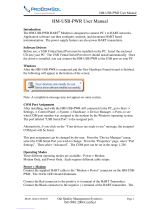
GENERAL OPERATION INFORMATION
42-109 Cutaway View
HANDSWITCH
A Handswitch allows local electric control at
the actuator. In either of the STOP
positions, the motor is blocked
or EXTEND positions, the
motor runs to move the output
the Handswitch, the motor will stop when the over-
travel limit switches are reached.
only when the Handswitch is in the AUTO position.
AUTOMATIC MODE
When the Handswitch is placed in the AUTO
position, the actuator is in automatic mode and
(DCM-3)
position. When the DCM-3 detects a difference
between Demand and Position (called error), the
motor will move the output shaft until the Position
matches the Demand.
MODES OF OPERATION
• Handwheel—local mechanical control
• Handswitch—local electrical control
• Automatic—remote electrical control
Any or all of these modes can be used to test basic
HANDWHEEL
The Handwheel permits manual operation
of the actuator without power. The Handwheel is
coupled directly to the motor shaft at the rear of the
initial installation or when power is not available. If
power is available, the Handswitch must be moved
the Handwheel.
(DCM-3)
Switches
Contactless Position Sensor
(CPS)
Motor & Handwheel
(not shown)
Clevis
Handswitch
Handwheel
Motor
Output Shaft Clevis

8
80-0042-01, Rev. 7.8
INSTALLATION Electrical
ELECTRICAL INSTALLATION
Two conduit connections are provided for
Conduits should be routed from below the actuator
so that condensation and other contaminants flow
away from the conduit. All conduit entrances must
be properly sealed in accordance with National
should be either shielded cables or be installed in
conductive conduit and/or cable trays.
up to 12 AWG (3.31 mm2
CAUTION
Always close covers immediately
after installation or service to prevent
moisture or other foreign matter
from entering the actuator.
your Beck actuator for proper AC power and
normal short circuit protection on the AC power
each actuator and is fastened to the inside of the
available, you may obtain a copy from Beck by
Your Beck actuator has been supplied to
resistor—contact the factory for details.
For maximum safety, the Beck actuator body
connected to the actuator body.
POWER QUALITY
Power quality disturbances such as power
and electrical noise will adversely affect your
from these conditions can reduce downtime and
the industry accepted standards below will help
protect your actuator.
a
aShielded, twisted pair cables can be used for
on Noise Susceptibility Level (NSL) per
A braided shield will be more effective than
source is required, then the shield should not
aRaceways such as conduits and trays must
immunity requirements.
a
made between the power source and the Beck
wire and metal conduit are permitted, but the
connected to a structured metal frame of a
a
Underwriters Laboratory (UL) Standard 1449
a
some measure of electrical noise protection.
a
CAUTION
Always close covers immediately
after installation or service to prevent
moisture or other foreign matter
from entering the actuator.

9
80-0042-01, Rev. 7.8
TERMINAL BLOCK LOCATED WITHIN THE
WIRING / DCM-3 COMPARTMENT
TERMINAL SCREW TORQUES
Each terminal screw should be torqued to the
Torque
Models Terminals (lb-in) (N•m)
All Models
AV 16 1.8
AAEE 12 1.4
13* 9 1.0
*Terminals included only with certain optional features.
FUSE (F1) 1 2 3
Three additional terminals and fuse (F1) are
provided with 3-phase power options.

10
80-0042-01, Rev. 7.8
INSTALLATION Wiring
TYPICAL WIRING CONNECTIONS
FEEDBACK
(120 V Power, Single-phase)
(240 V Power, Single-phase)
Alternate Power
Options (3-phase)
K1-6
K1-8
K1-7
K1
K1-1
K1 K1
K1-5
K1-4
K1-2 K1-3
TERMINAL BLOCK CONFIGURATION JUMPERS
J1 J2 J4 J6 J7 J8 J9 J10 J11
Standard D-N F-M
Status Alarm Contact D-N F-M B-K1-1 E-K1-2
Ext on Relay Action D-K1-3 F-K1-6 N-K1-4 M-K1-7
Ret on Relay Action D-K1-3 F-K1-6 N-K1-4 M-K1-7 C-K1-8
Stop on Relay Action D-K1-3 F-K1-6 N-K1-4 M-K1-7
Int on Relay Action D-K1-3 F-K1-6 N-K1-4 M-K1-7 C-S S-P J-K1-8
K-K1-8
Assembly installed on terminal block.
POWER AND
DEMAND INPUT
CONNECTIONS
Customer must
supply appropriate
proper terminals
(as depicted in the
to power the actuator
and control circuitry.
connect to terminals
POWER
CONNECTIONS
Same as 240 V Single-phase,
except where highlighted.
(208/240 V Power)
(380/415/480/575 V Power)

11
80-0042-01, Rev. 7.8
START-UP
START-UP
NOTE: All Beck actuators are shipped from the
factory ready for installation. Each actuator
is set-up and calibrated to the customer’s
specifications that were written into the
equipment order. Electrical adjustments are
generally not required before placing the
actuator in operation.
START-UP CHECKLIST
actuator into operation.
Be sure the actuator is securely fastened to its
STOP position to ensure that the output shaft will
Check the DCM-3 Power LED. It should be
active.
moves fully to both the EXT and RET ends of
travel.
Place the Handswitch in AUTO and vary your
Check for the Status alarm LED on the DCM-3.
this manual.
of output shaft rotation.

12
80-0042-01, Rev. 7.8
COMPONENTS Mechanical
HANDSWITCH
A local electric Handswitch is provided on Beck
actuators to permit operation indepen dent of the
controller. As a safety feature, the Handswitch is
actuator only when it is in the “AUTO” position. The
“RETRACT”, “STOP”, “EXTEND”.
In the “AUTO” position, two contacts are closed
and the DCM-3 completes the control circuit. In
the “RETRACT” or “EXTEND” positions, contacts
are closed to operate the actuator independently of
the controller. In the “STOP” position, all contacts
remain open.
SWITCHES
Two over-travel limit switches and up to two
optional auxiliary switches are provided on Beck
actuators. Switch cams are clamped onto the
control shaft which rotates in relation to the output
connections are made on the terminal block.
HOUSING
Beck Group 42 actuators have individual cast
drive train and control end. Gasketed covers and
sealed shafts make the actuators ideally suited to
Heavy cast mechanical stops built into the
that proper orientation is maintained be tween the
output shaft and the feedback system. Actuator
travel is centered between the mechanical stops
CONTROL MOTOR
The Beck control motor is a synchronous
inductor motor which operates at a constant
speed of 72 RPM in synchronism with the
line frequency. Motors are able to reach full
times will vary with load. Beck motors have
maintenance for the life of the motor.
DRIVE TRAIN
The drive train consists of the control motor,
shaft. The output shaft is limited by mechanical
SELF-LOCKING
MECHANISM (SLM)
motor torque when rotated in either direction. When
locks and holds the output shaft in position.
HANDWHEEL
Every Beck actuator is furnished with a Handwheel
to permit manual operation of the driven element
safe, slow speed. The Handwheel is located at the
coupled directly to the motor shaft and rotates when
the motor runs. Manual operation of the Handwheel
(with electric Handswitch in “STOP” position) turns
the motor and the rest of the actuator train without

13
80-0042-01, Rev. 7.8
COMPONENTS Electronic
CONTACTLESS POSITION
SENSOR (CPS-4)
The CPS provides the DCM-3 with a continuous
actuator’s output shaft.
by the DCM-3 to control the actuator. The typical
available for remote position indication. If the CPS
terminal E .
DIGITAL CONTROL MODULE
(DCM-3)
The DCM-3 is a micro-processor based circuit
board assembly that serves as the actuator’s
control center.
The main function of the DCM-3 is to position
the actuator’s output shaft. The DCM-3 compares
actuator terminals AA(+) and BB () to the actuator
Position Sensor (CPS-4). If a difference exists
(called error) between the Demand and Position
positions the output shaft until the difference is
eliminated.
includes the fuse and test point locations. The
1.0 V dc at the Extend end of output shaft travel,
to 4.0 V dc at the Retract end of output shaft
DCM-3
CPS-4

14
80-0042-01, Rev. 7.8
INTERFACES
PUSHBUTTON
.
HART
communicator) to terminals
SERIAL PORT
Communicator
Terminal Block
AA & BB
HART
Cable
COMPONENTS Electronic
DCM-3 Pushbuttons
Laptop
Computer
DB9 to USB
Cable
DB9
Serial Port

80-0042-01, Rev. 7.8
OVERVIEW LEDs
OVERVIEW LEDs
Located on the DCM-3 board (pictured above),
these LEDs indicate the basic, real-time state of
the actuator. A description of each LED follows.
STAT
Explanation of the specific alarm is available
REV
FWD
PWR
DCM-3
LAYOUT
Mounng Screws
(4 places)
Torque Sensing
Connector
Overview LEDs
Direcon LEDs
Serial Port
Fuse (ensure
cover is in
place before
energizing)
Test Point 4
(TP4)
Test
Point 2
(TP2)
Test
Point 3
(TP3)
Test Point 1
(TP1)
Status
Indicaon LEDs
Pushbuons
DIRECTION LEDs
DIRECTION
LEDs
A = RET B = EXT
R11

16
80-0042-01, Rev. 7.8
COMPONENTS Electronic
STATUS INDICATION LEDs
When the “STAT” LED is lit, the applicable red indication
alarm is also available at terminal E. When the condition
is corrected, the status will automatically reset.
DEMAND
POSITION
TRQ/THRST
This LED indicates that excessive torque is present
STALL
The actuator is in a stall condition and stall protection
has been activated.
TEMP °F.
FB OPEN
PUSHBUTTON CONTROLS
The five pushbuttons (pictured below) on the
DCM-3 customer interface panel are used for
should be maintained until the “ACK”
confirms receipt of the pushbutton command. See
the C/Calibration section of this manual
for further explanation of calibration procedures.
CALIBRATE
This button must be pressed and held simultaneously
with another pushbutton to perform a calibration.
CAUTION
Pressing the
following buttons
may change
calibration and
cause the actuator
to reposition.
STATUS INDICATION LEDs
PUSHBUTTON CONTROLS
STOP/LIMIT
Handswitch is in “STOP” position or the actuator is at
a limit and is not in balance.
ACK
completed.
SET POS 100%
shaft as the 100% position for actuator movement (this
SET POS 0%
shaft as the 0% position for actuator movement (this
SET DEM 100%
as 100% Demand.
SET DEM 0%
as 0% Demand.
DIR SEL

17
80-0042-01, Rev. 7.8
CONFIGURATION/CALIBRATION
All Beck actuators are shipped completely
were written into the equipment order and are
the actuator calibration, first confirm that the
Position reference and Demand calibration are
or Serial interface. Calibration of over-travel limit
CALIBRATION PRIORITY
output shaft movement must occur within these
stops, which are approximately 1/8" beyond each
.
The over-travel limit switches are used to
These switches are cam operated and are set
are positioned to provide an electrical overtravel
protection.
If the actuator is short-stroked—i.e., full travel
is reduced to less than the standard span—it may
be desirable to reset the over-travel limit switches
Handswitch operation of the actuator (Retract,
of travel. It is best to calibrate the actuator and
the 0% and 100% positions.
The auxiliary switches are also cam operated,
but have no affect on actuator and DCM-3
operation. Therefore, the auxiliary switches can be
or calibration.

18
80-0042-01, Rev. 7.8
SWITCH CALIBRATION
NOTE: All Beck actuators are shipped from
the factory ready for installation; no electrical
adjustments are required before placing them
in operation. Each actuator is set up and
calibrated to the customer’s specications
that were written into the equipment order.
no need to recalibrate the actuator. However,
Switch Adjustments
All control actuators are shipped with
time of order). The switches are set to provide
electrical over-travel protection. The switches
mechanical stops. The switches can be reset to
accommodate limited travel of the output shaft.
Auxiliary switches are factory set, as shown in
at time of order.
Switches are operated by cams which are
that it operates the switch at that point. In the
is recommended to determine when the switch
opens or closes. If such a meter is not available, it
is possible to hear the switch click as the contacts
open and close.
CAUTION
Do not attach the meter or attempt
to move the switch cams until the
actuator is disconnected from the
line voltage and auxiliary switches
are disconnected from external
power sources.
Setting Over-travel Protection
Switches S3 (Retract) and S4
(Extend)
This procedure should be used if the factory
1. Remove the control end cover and terminal
block/DCM-3 cover (1/2" bolt heads).
2. Retract the output shaft to the end of travel
limit.
3. Turn the Handswitch to the STOP position.
4. Use the Handwheel to position the output shaft
at the desired over-travel limit.
6. Connect the continuity meter across the
appropriate terminals. Refer to your actuator
continuity (switch contacts closed, switch
clicks).
EXTEND
RETRACT
CONTACTS CLOSED
CONTACTS OPEN
S1
S2
OVER-TRAVEL
PROTECTION SWITCHES
SET OUTSIDE OF
TRAVEL RANGE, BUT
INSIDE MECHANICAL STOPS
2 AUXILIARY SWITCHES
SET 2% INSIDE OF FACTORY-
CALIBRATED STROKE LENGTH
Note: The switch contacts
are shown at midpoint
of travel.
RETRACT
LIMIT
EXTEND
LIMIT
Standard Over-travel Protection and
Auxiliary Switch Settings
2% 2%
K
S J
GP
H
CONFIGURATION/CALIBRATION

19
80-0042-01, Rev. 7.8
8. Use the Handwheel and confirm that the
and closed at the desired over-travel limit.
9. Disconnect the meter and reconnect actuator
power.
that referenced directions of travel should be
opposite of those used for the Retract switch
Setting Auxiliary Switches
of shaft travel. The heavy line indicates a closed
CONTROL END / CONTACTLESS POSITION SENSOR
NOTE: In the following procedure, it is
assumed that switch settings are to be
adjusted so that contacts are open when the
desired position is achieved.
1. Remove the control end cover and the terminal
block cover (1/2" bolt heads).
2. Move the output shaft to the desired position.
3. Turn the Handswitch to the STOP position.
4. Disconnect power from the actuator and switch
terminals.
appropriate terminals. Refer to your actuator
continuity (switch contacts closed, switch
clicks).
7. Disconnect the meter and reconnect power.
8. Move the actuator’s output shaft in the desired
direction so that the cam lobe moves away from
the switch lever. If not correct, return to step 2
and reset the cam to the proper orientation.
CAM DETAIL
PIN
CONNECTORS
AUXILIARY
COUPLING
EXTEND SWITCH (S4)
CAMS
RETRACT SWITCH (S3)

20
80-0042-01, Rev. 7.8
CONFIGURATION/CALIBRATION
DIRECTION OF OUTPUT SHAFT
TRAVEL (EXTEND VS. RETRACT)
Travel direction of the actuator is determined
order, the output shaft is factory-set to extend in
methods.
Pushbutton method
1. Remove the DCM-3 cover (1/2” bolt heads).
2. Position the actuator at the current 0% position.
3. Press and hold the “CALIBRATE” pushbutton
on the DCM-3 local interface panel, then press
the “SET POS 100%” pushbutton until the
“ACKNOWLEDGE” LED is lit.*
—OR—
2. Position the actuator at the current 100%
position.
3. Press and hold the “CALIBRATE” pushbutton
on the DCM-3 local interface panel, then
press the “SET POS 0%” pushbutton until the
“ACKNOWLEDGE” LED is lit.*
4. Ensure the actuator operates as desired.
cover bolts to 10 lb-ft (14 N•m) torque.
*
accepted by the DCM-3.
NOTE
performed, both the 0% and 100% positions are
automatically set.
HART method
Command: Actuator Dir
DD Menu Location: MENU 4B
Selections:
RET Incr - select if the desired output shaft
EXT Incr - select if the desired output shaft rotation
Serial command method
Command: drvdir n
Arguments: n
0: Retract - select if the desired output shaft
1: Extend - select if the desired output shaft
EXTEND
RETRACT
/